Abstract
We have developed a stent motor that can move in the blood vessel by applying the technique of the ultrasonic motor. First, we have designed a horn to provide ultrasonic energy to the stent from outside of human body. Second, we have also designed a stent motor that consists of two parts; a stator and receivers. The receiver unit obtains the ultrasonic wave from outside. The stator is the coil shape and it can move smoothly in intravascular. Finally, we have made experiments by the horn and stent motor. We have succeeded in driving the stent motor back and forth in the water.
1. Introduction
Recently in Japan, ischemic heart disease, such as myocardial infarction is the higher rank of a main cause of death. Ischemic heart disease arises in the coronary arteries. A plaque accumulates over many years to 70-80 % of inner blood vessels. If it strangulates, stable exertion angina will arise and strangulation will advance to a blockade of blood vessels. Early detection and medical treatment are desired in these diseases. In order to solve it, a balloon angioplasty is widely used, and coronary artery in intervention has become a main cure treatment. A stent is a today’s medical treatment instrument, which is also widely used with a balloon formation way in order to support formation of a blood vessel from an inner side and to maintain extension of a blood vessel mechanically. In our research, we applied the technology of an ultrasonic motor to the stent [1-3]. We aim at developing the stent motor which moves inside of a blood vessel by irradiating with an ultrasonic wave from the outside of the body to expand the blood vessel.
2. Driving principle of stent motor
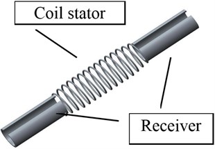
A stent motor is a motor that rotates in a blood vessel forward and backward. Fig. 1 shows the schematic view of a stent motor. The energy for driving is supplied by ultrasonic irradiation from the outside of the body. Therefore, a stent motor receives an ultrasonic wave, and receiver generates traveling wave to produce thrust force. The receivers are set at both ends of a stator. Each receiver can be resonated by irradiating with the ultrasonic wave of some resonant frequency. Their resonant frequencies are different from each other. Thereby, a stent motor can move back and forth.
Fig. 1Overview of stent motor
The drive principle of the stent motor is same as that of the conventional ultrasonic motor, that is to say, friction motor. Based on the friction motor model, the output torque is shown as follows:
where is contact force between stator and rotor, dynamic frictional coefficient is and coil’s radius is . One point of the surface of the coil draws an elliptical motion. Its vertical motion and horizontal motion are described as single vibration:
In the case that the contact force is applied to stator and rotor, is equal to the sum of impact force generated at the top of elliptical motion. Now we assume that quarter of wavelength makes impact, the density of stator is , section area is , acoustic impedance is and the velocity of sound is . The mass contributing to the impact is as follows:
The average speed of the mass is as follows:
An impact force is derived from impulse rule as:
Also, we derive the torsional speed and output torque as:
From Eq. (1), (6) and (8), ovality is obtained:
3. Theory of Stent motor
We have built a theoretical formula of this motor. First, we derive the output wattage density at the tip of a vibrator of an ultrasonic wave generation machine. We assume that wattage of an ultrasonic wave generation machine is , a horn’s tip area is , the output frequency , the amplitude of the ultrasonic wave is and the intrinsic impedance of a human body is . The output watt density of a vibrator apical portion is described as the following:
Next, we will derive a theoretical formula of attenuation from the ultrasonic wave generated at the horn tip to the receiver of a stent motor, and show the output watt density that a stent receives.
We assume that the distance between the receiver and vibration generator is and amplitude of the ultrasonic wave at the receiver is , is generally described as follows:
where is attenuation factor.
The coefficient is increasing as the power of two as the frequency of the sound increases. But, it increases lineally in human body.
The incidence rate of the ultrasonic wave from a human body to a receiver is:
It yields the wattage density as:
Secondly, we will discuss the transmission of wave from the receiver to stator. We assume that there is no loss of energy in transmission. The wattage density of the stator is:
where areas of receiver’s transmission and stator’s transmission is and respectively.
From Eq. (16) and Eq. (9), we obtain amplitude of stator’s vibration as:
The output torque of stent motor is:
where is stator’s contact length as described as:
is number of turns of coil and is pitch.
From Eqs. (11), (18), (19) and (20), is rewritten as:
Finally, we obtain the output torque and thrust force as:
4. Design of stent motor and horn of wave generator and experiments
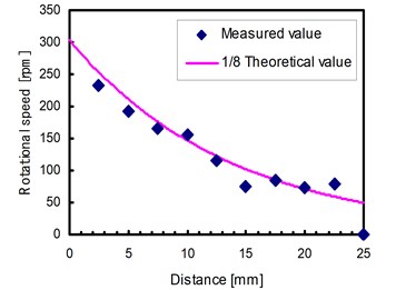
A newly designed stent motor’s receiver has the same frequency of the ultrasonic homogenizer (26 kHz). The size of the stent motor is diameter 4.1 mm and length 27 mm. This is a size equivalent to the stent actually used by the coronary arteries. Further it has frequency adjustment slit at the side of a cylinder. An experimental result is shown in Fig. 2. It shows that we have succeeded in driving the stent motor. Its driving direction is controllable by irradiating ultrasonic wave. The motor is working in the range of 0 mm-25 mm. But, the motor cannot move in the place where the distance of an ultrasonic wave supply horn and a stent motor is more than 25 mm.
The maximum rotational speed is determined by the speed of torsional oscillation. It has radius velocity component and axial velocity component.
From Eq. (3), the radial component of is:
From Eq. (24), we obtain maximum rotational velocity as:
We apply the real value to this equation to draw characteristics of rotational velocity and distance as shown in Fig. 2:
In our experiment, a rotor has not rotated at the point where the distance of a horn and a stent motor is 25 mm. The experimental rotational velocity is about 1/8 of that of the theoretical figures acquired from Eq. (28). It is because that a theoretical contact force between stator and rotor is larger than experimental one and the coefficient of friction became smaller in the water. However, since the downward tendencies as a theoretical figure in Fig. 2 is same as the experimental result, the theoretical model is correct.
Fig. 2Rotational speed vs. distance
5. Conclusions
In this research, firstly, we derived the theoretical formula about the output of the stent motor. Next, we have designed the stent motor and the horn and made the experiments of driving it to show the fundamental characteristic. Its rotational direction is controllable by irradiating a stent with the ultrasonic wave of the resonance frequency. Under the actual usage environment of a stent motor, we presume that it generates a low output further rather than this experimental condition by low coefficient of friction of a blood vessel inner wall, unstable contact force and the lubricating effect of blood.
References
-
Moriya T., Furukawa Y., Akano Y., Nakajima A. IECEI Technical Report, No. US2005-29, 2005.
-
Takesue N. Position control methods of spherical ultrasonic motor proc. International Conference on Intelligent Robots and Systems, 2010, p. 3061-3066.
-
Sashida A., Kenjo T. An Introduction to Ultrasonic Motors. Oxford Press, 1993.
About this article

