Abstract
This paper presents the modeling, analysis and performance comparison of passive, semi-active and active controlled suspension systems of an automobile. Starting from a simplified quarter car suspension model, a frequency analysis in a proposed passive suspension is made, evaluating its performance against the variation of some of its parameters. Subsequently, a comparison between the passive and actuated (semi-active) suspension systems is presented, so as to show their advantages and disadvantages. Finally, several types of semi-active suspension controllers are proposed (modified Skyhook, modified Groundhook, PID, Model predictive control) and compared to each other.
1. Introduction
The suspension system of a road vehicle has two main objectives: the first one is to ensure the comfort of the passengers, and the second one is to keep a good grip (road holding) between the tires and the ground, in order to improve traction and handling of the vehicle. The comfort is directly related to the vertical acceleration of the sprung mass of the vehicle, whereas the safe driving can be associated with the quality of contact (holding) between the wheels and the ground surface [1]. The two objectives are competitive, so the proper tuning of a suspension system has to deal with a tradeoff between them.
One alternative to improve the response of the suspensions is to complement the classical passive scheme with the inclusion of semi-active components, and also with the implementation of control systems over the new components. In the controlled suspensions, the Skyhook theory has been used extensively in the literature [2, 3] and has shown good performance in terms of the comfort of the passengers, but is limited in the road holding of the tires. On the other hand, the control scheme has been proposed on linear time invariant systems (LTI), and has shown that it can lead to the controlled suspension to maintain a good compromise in terms of the comfort and the safety of the passengers [4, 5]. However, it is limited to a fixed performance and therefore cannot be tuned in order to drive the controller to an improvement in comfort, or an improvement in the road holding.
The actuated suspensions seek to obtain the best compromise between operational cost (e.g. energy consumption, sensors and actuators) and performance (e.g. requirements of comfort and safety). The semi-active suspensions arise as a good solution to this compromise, since they achieve a better performance than passive suspensions (as it will be exposed below), and require a much lower cost than active suspensions (e.g. price and time response). In order to ensure their best performance, several strategies of control have been developed, such as those presented in [6-10]. In these studies, the main actuator is proposed as a shock absorber with magnetorheological fluid, since it appears to be a good solution for the implementation of the semi-active control systems in a car’s suspension. The dampers with these characteristics have a large force capacity and provide a simple, fast and robust interface between electronic controls and mechanical components of the vehicle.
This paper presents the modeling, analysis and performance comparison of semi-active controlled suspension systems of an automobile, in order to find the best compromise between the comfort of the passengers and the road holding. Mathematical models of quarter car were developed. The passive suspension system was characterized analyzing its behavior at a wide range of input frequencies. A comparison between the passive and actuated suspension systems is presented. The results of this comparison are used to show the advantages and disadvantages of each option in terms of its performance in the chosen indicators, and their ease of implementation.
2. Methodology
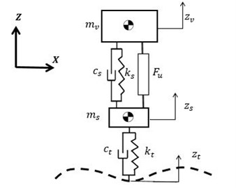
For the analysis of the different suspension systems, a set of quarter car suspension models were implemented. The scheme of the model is presented in Fig. 1. The models were adapted to include several morphologies of controllable dampers [11]. The dynamic behavior of the passive system was studied before the inclusion of it control. The system was characterized and the frequencies in which the isolation is needed were identified. The system analysis was performed based on its frequency response.
Fig. 1Scheme of the model of a quarter car suspension system
For the study, the performance indicators chosen for the evaluation of the suspensions were the passengers comfort and the grip between the tires and the ground. The chosen comfort indicator is the ratio between the response of the chassis displacement and the different inputs of the terrain . For this, the transfer function is used. For the evaluation of the grip, the vertical deflection of the tires was chosen as indicator. It is computed as the difference between the suspension displacement and the ground perturbations The transfer function is used. With the given definition, the objective with both indicators is to minimize their value. Both indicators were evaluated for frequencies between 0.1 Hz and 30 Hz.
Table 1Parameters of the vehicle’s simplified suspension model
Parameter | Value | Units |
1248.5 | kg | |
117.4 | kg | |
144195 | N/m | |
6259 | Ns/m | |
1240000 | N/m | |
2871 | Ns/m |
For the inclusion of the control systems, the quarter car models were developed including as a control variable. This variable represents the controlled force of the semi-active component that is mounted between the unsprung and the sprung masses. In order to consider only semi-active systems, passivity constraints were included.
A set of different control strategies were compared, namely modified Skyhook control [12], modified Groundhook, and Power Driven Damper Control (PDD) [13], PID controllers and Model Predictive Controller (MPC) [14-16]. For each control strategy, different configurations were simulated. In each case, both performance indicators were computed and compared.
Skyhook strategy is based on the idea that the car body is joined to a frame in the “sky”, in order to reduce vertical oscillations of the sprung mass. Therefore, the skyhook is considered as a proposal of comfort-oriented controlled suspension. The union between the vehicle mass and the framework in the “sky” is a damper. A modified Skyhook includes parameter variation, with the inclusion of a parameter for the definition of a given control law, shown in Eq. (1). The saturation function limits the values so that :
PDD control law for a semi-active suspension is proposed in [13], where the Port-Hamiltonians technics are used for its deduction. The control law is shown in Eq. (2):
Groundhook control law consists, basically, in the on/off strategy that allows varying the equivalent damping of the suspension according to the physical limits of the variable damper []. The controller input is not the velocity of the sprung mass but the velocity of the unsprung mass, . The modified Groundhook control law is presented in Eq. (3):
Three PID controllers were implemented. For each case, the control law was designed so that when facing a perturbation from the road the controller takes back the output signal to its equilibrium position in zero. The first case of PID controllers corresponds to a comfort-oriented suspension, where the error was defined according to Eq. (4):
The second case of PID controllers corresponds to a grip-oriented suspension, where the error was defined according to Eq. (5):
The third case of PID controllers corresponds to a combined suspension, where the error was defined according to Eq. (6):
Three models of predictive controllers (MPC) where implemented. The definition of the different controllers corresponds to different cost functions to be minimized. The optimal control action is minimizing the cost function over a prediction horizon. The cost function is defined in Eq. (7), according to a prediction horizon and a control horizon, , taking into account that there is not penalization of the control signal , due to the fast dynamics of the actuator. In the equation, denotes the value of the prediction at the time . This prediction is calculated according to the information available at time . is the value of the reference at the current time :
where the variables and represent the weights (i.e. penalizations) for the output error () and the control signal error , respectively. represents the number of system outputs to optimize, while represents the number of control signals (controller outputs).
The cost function can be defined comfort-oriented as shown in Eq. (8), road-holding oriented as shown in Eq. (9), and according to a combination of the two as shown in Eq. (10). For the first two cases 1 and for the third case 2. For the three cases 1 and :
3. Results: passive vehicle suspension
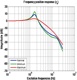
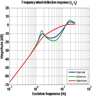
The numeric simulations of the passive suspension system were made with 3 different values of the damping coefficient, so as to highlight the change of the dynamic response with the change of the parameter . As the nominal value of the equivalent damping coefficient in the suspension (Table 1) was used, for the minimum value of the damping was used, and finally for the maximum value of the equivalent damping of the suspension was proposed. The Bode plots of the 3 previously defined suspension systems are shown in the Fig. 2.
In Fig. 2(a), the performance index of the comfort-oriented vehicle suspension is presented. It can be seen that the system amplifies the amplitude of the input signal for frequencies lower than 2.3 Hz, whereas isolates vibrations at frequencies above 2.3 Hz. In Fig. 2(b), the performance index of the road holding-oriented vehicle suspension is presented. It can be seen that the system isolates the vibrations that occur at frequencies lower than 12.5 Hz, while amplifies the amplitude of the input signal for frequencies above 12.5 Hz, so that the road holding is more variable and thus, makes the vehicle unsafe by losing traction and maneuverability. This condition shows that the tire grip and the comfort are competitive indices.
Fig. 2(a) shows that at a low excitation frequency of the system, a suspension with a high value of the equivalent damping coefficient successfully isolates the amplitude of the input signal, compared to a suspension with a low equivalent damping coefficient. For high frequencies, a passive suspension with low damping coefficient has a better vibration isolation behavior compared to a suspension with high damping. Fig. 2(b) shows that a suspension with high damping coefficient, guarantees good results in terms of the wheel deflection response in the resonance frequency of the sprung mass, and the resonance frequency of the unsprung mass. However, in the domain frequencies between 2.3 Hz and 12.5 Hz, a low damping coefficient suspension provides better results.
Fig. 2Frequency response of the passive vehicle suspension, for three different cs: a) sprung mass vertical position; b) wheel deflection
a)
b)
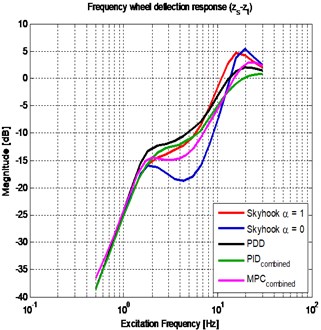
4. Results: semi-active vehicle suspensions with different control strategies
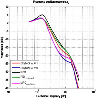
After the revision of the results for all the considered cases, a selection with the five most relevant behaviors was done. The chosen controllers are the following: Modified Skyhook , traditional Skyhook 1, Power driven damper control, combined PID and combined MPC. Fig. 3 presents the frequency response of the two performance indices of the chosen controllers. There are three zones to emphasize: the first zone corresponds to the frequencies around 2.3 Hz where the response can be described as mainly sprung mass motion. The second zone corresponds to the frequencies around 12.5 Hz where the response can be described as mainly unsprung mass motion. The third zone corresponds to a transition zone between zones 1 and 2.
Fig. 3Frequency response of the semi-active with the different controllers: a) sprung mass vertical position; b) wheel deflection
a)
b)
5. Conclusions
An analysis of the performance of different semi-active suspensions, for a frequency range between 0.1 Hz and 30 Hz was performed by means of a quarter car suspension model. A comparison of different types of control algorithms was made, considering two indices: comfort and grip.
The traditional Skyhook improves the comfort performance compared to the passive suspension, but its grip performance is poor. This is consistent with the fact that this control strategy is comfort oriented. In the same family of strategies, modified skyhook (i.e. 0) has a better performance than traditional skyhook. Modified Skyhook has a drawback in grip performance around the natural frequency of the vibration mode associated mainly to the displacement of the unsprung mass.
PDD control algorithm has a good compromise between comfort and grip for the different frequencies. This control strategy has also an advantage associated to its implementation, as it only required the same transducers as a Skyhook strategy.
For the case of PID and MPC strategies, the combined versions were the better option to deal with the competitive indices. Combined PID and combined MPC strategies have the higher improvement between the different strategies studied. Combined PID strategy presents good performance for both indices. Combined MPC strategy presents a better result for most of the frequencies. MPC presents the best performance for the relevant frequencies in comfort, and it has also a good grip performance, mainly for frequencies under 16 Hz. For its implementation the amount of required information must be considered, taking into account both the number of required signals and the required prediction horizon.
References
-
Belingardi G., M. Demic. A possible model for shock absorber by using “black box” method. Journal of Applied Engineering Science, Vol. 7, Issue 4, 2009, p. 45-53.
-
Sammier D., Sename O., Dugard L. Skyhook and H8 Control of Semi-active Suspensions: Some Practical Aspects. Vehicle System Dynamics, Vol. 39, Issue 4, 2003, p. 279-308.
-
Poussot-Vassal C., Sename O., Dugard L., Ramirez-Mendoza R., L. Flores. Optimal skyhook control for semi-active suspensions. Proceedings of the 4th IFAC Symposium of Mechatronic Systems, Vol. 4, Issue 1, 2006, p. 608-631.
-
Zin A., Sename O., Dugard L. Switched H-inf control strategy of automotive active suspensions. Proceedings of the 16th IFAC World Congress, 2005.
-
Rossi C., Lucente G. H-inf control of automotive semi-active suspensions. Proceedings of the 1st IFAC Symposium on Advances in Automotive Control, 2004.
-
Du H., Yim Sze K. and Lam J. Semi-active H – inf control of vehicle suspension with magneto-rheological dampers. Journal of Sound and Vibration, Vol. 283, Issue 3-5, 2005, p. 981-996.
-
Ahmadian M., Reichert B., Song X. System non-linearities induced by skyhook dampers. Shock and Vibration, Vol. 8, Issue 2, 2001, p. 95-104.
-
Liao W., Wang D. Semiactive vibration control of train suspension systems via magnetorheological dampers. Journal of intelligent material systems and structures, Vol. 14, Issue 3, 2003, p. 161-172.
-
Ikhouane F., Rodellar J. Systems with Hysteresis: Analysis, Identification and Control Using the Bouc-Wen Model. Wiley, 2007.
-
Choi S., Nam M., Lee B. Vibration control of a MR seat damper for commercial vehicles. Journal of Intelligent Material Systems and Structures, Vol. 11, Issue 12, 2000, p. 936-944.
-
Savaresi S., Poussot-Vassal C., Spelta C., Sename O., Dugard L. Semi-Active Suspension Control Design for Vehicles. Elsevier, London, 2010.
-
Emura J., Kakizaki S., Yamaoka F., Nakamura M. Development of the Semi-Active Suspension System Based on the Sky-Hook Damper Theory. SAE Technical Paper, No. 940863, 1994.
-
Morselli R. and Zanasi R. Control of port Hamiltonian systems by dissipative devices and its application to improve the semi-active suspension behavior. Mechatronics, Vol. 18, Issue 7, 2008, p. 364-369.
-
Bemporad A., Morari M. Robust Model Predictive Control: a Survey. Robustness in Identification and Control. Springer, 1999.
-
Wang L. Model Predictive Control System Design and Implementation Using MATLAB. Springer, 2009.
-
Mayne D., Rawlings J., Rao C., Scokaert P. Constrained model predictive control: Stability and optimality. Automatica, Vol. 36, Issue 6, 2000, p. 789-814.
About this article

