Abstract
This study proposes a stent motor as a medical device. A stent is a medical instrument inserted in a constricted part of a blood vessel to expand the blood vessel. However, the problem is that plaque accumulates around the installed stent and causes the blood vessel to narrow again. A stent motor is used to remove plaque. A stent motor consists of a receiver part to receive ultrasonic vibration and a stator part to drive the motor in the blood vessel. The purpose of this study was to develop a stent motor and determine its optimum design. It was possible to drive a stent motor by subjecting a disk-shaped receiver to strong ultrasonic vibrations. Experiments were performed on the stent motor with several types of receivers by changing their size and shape, and the efficiency was evaluated. Correlation between the design of the stent motor, such as the number of turns in the stator and the shape of the receiver, and the rotational speed was clarified.
Highlights
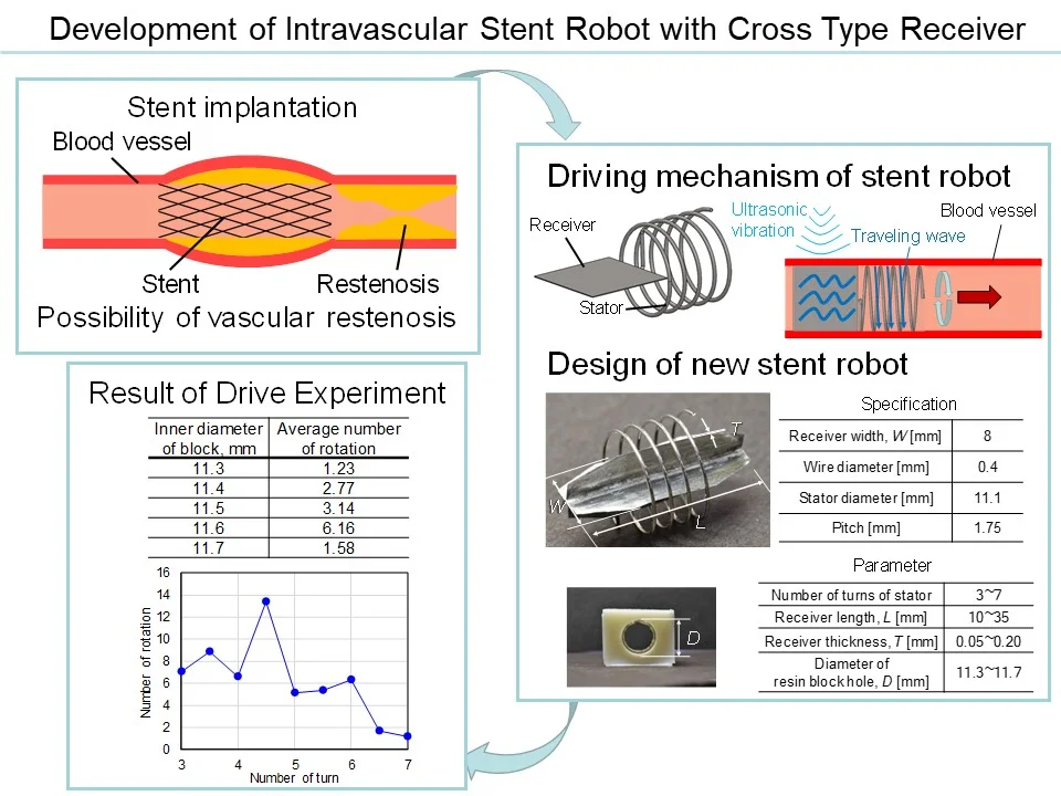
- Stent implantation
- Driving mechanism of stent robot
- Design of new stent robot
- Result of Drive experiment
1. Introduction
Heart disease has been one of the three major causes of death in Japan, and in 2017, it became the second most common cause of death. An example of heart disease is ischemic heart disease, which includes angina and myocardial infarction. These diseases are caused by the buildup of cholesterol in the inner vascular walls of the coronary artery, which leads to constricted blood vessels. It is treated through stent placement. A mesh-like metal cylinder called a stent is placed in the constricted area on the inside of a blood vessel to ensure patency. However, constriction sometimes reoccurs near the stent after surgery, and further surgery is required. Adjusting the stent position without surgery would make it possible to reduce patient burden. Thus, we have developed a stent motor that slides within blood vessels as a result of extracorporeal ultrasound irradiation [1-3].
Here, we conducted stent motor experiments in water, preceded by experiments in simulated blood. These experiments were conducted for rotating the stent motor with ultrasound vibrations in water to examine the effects of its shape and other conditions on the rotations.
2. Receiver vibration frequency identification experiments
2.1. Experimental method
We built a stent motor as shown in Fig. 1. The receiver part is usually circular, but here it was octagonal to simplify construction. The receiver and stator were made with SUS304 and soldered with stainless steel solder. We placed the stent motor in water and measured the receiver vibrations when radiating ultrasound vibrations with an ultrasonic homogenizer (Q500, QSONICA) using a laser displacement sensor (LK-H050, KEYENCE). Subsequently, we located the tip of the ultrasonic homogenizer at a water depth of 20 mm and located the center of the receiver 15 mm perpendicular and 50 mm horizontal to the center of the ultrasonic homogenizer tip. We performed measurements under the same conditions 30 times.
Fig. 1Stent motor without hole
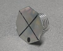
Fig. 2Fourier analysis of receiver vibration
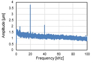
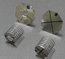
Fig. 3Stent motor with different sized receivers
2.2. Experimental results
We performed Fourier analysis of each receiver displacement measured with the laser displacement sensor and obtained the average. Fig. 2 shows the results. From the figure, we observed a peak at the vibrations of 20.02 Hz. The ultrasonic homogenizer used in the experiments automatically detected the converter resonance frequency and performed minute frequency adjustments using 20 kHz as a reference for the output frequency. Consequently, in the present experiments, the receiver vibrated at the frequency of the radiated ultrasound vibrations.
3. Stent motor rotation experiments
3.1. Manufacturing of stent motor and resin block
We manufactured receivers with metal plate diagonals of length 11 mm and 21 mm and then assembled the stent motor. Here, the diagonal length of the receiver i.e., 21 mm was larger than the coil outer diameter of the stator part, making the receiver unsuitable for its original application of insertion into a blood vessel. However, in the present experiments, we designed it this way to examine the rotational speed owing to differences in the receiver surface area. In addition, we needed to consider a shape that did not obstruct blood flow and thus manufactured a receiver with an open hole of 5 mm in diameter in the center for comparison. Fig. 3 shows the manufactured stent motor.
In the experiments here, we aimed to ensure frictional force by increasing the contact area and to eliminate effects other than the rotation direction, preceded by experiments in blood vessels, and then manufactured a device providing female thread holes in a resin block. We machined MC nylon in a cube shape with the side of 25 mm, and then used an M12 coarse screw tap in the center to provide a screw thread.
3.2. Experimental method
We placed the ultrasonic homogenizer so that the horn tip part was located at a water depth of 20 mm. In addition, the vertical distance between the horn tip part and the block top surface was 15 mm, and the horizontal distance between the tip part center and the receiver center was 10 mm. The resin block was placed so that the threaded screw hole was vertical, and the stent motor stator was inserted therein. Experiments were conducted 25 times with an ultrasound vibration irradiation time of 2 min and an ultrasonic homogenizer output setting of 50 % (35.4 W). The stent motor rotations were stopped every 90°, and the time required for rotation per interval was measured.
3.3. Experimental results
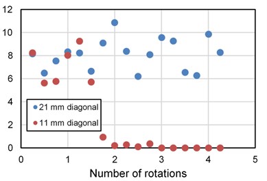
When ultrasound was irradiated, we confirmed that the stent motor rotates clockwise when observed from above. Fig. 4 and Fig. 5 show the average of the measurement results from the 25 experiments per interval. Table 1 shows the average values of rotational speed over all intervals per stent, and Table 2 shows the area of each receiver. However, we obtained the average of only the rotating places for stent motors using receivers with holes and a diagonal length of 11 mm that were stopped mid-rotation.
In Fig. 4 and Fig. 5, out of 17 places that were measured, the rotational speed of 21 mm stent motors quickened at half or more points. In addition, Table 1 confirms that, regarding the overall average speed, the rotational speed of the 21 mm stent motor is high. This is believed to be because ultrasound vibrations are more often received when the receiver area is large, and large vibration energy is transmitted to the stator. In addition, when we compare the rotational speed of the receivers with the same diagonal length, we observe that the rotational speed of shapes with holes is slower. This is believed to be due to the decreased receiver area from opening holes.
Table 1Average rotational speed
Diagonal, [mm] | Rotational speed [rpm] | |
Without hole | With hole | |
11 | 6.99 | 4.05 |
21 | 10.76 | 8.10 |
Table 2Area of the receivers
Diagonal, [mm] | Area of receiver [mm]2 | |
Without hole | With hole | |
11 | 85.6 | 65.9 |
21 | 311.8 | 292.2 |
Fig. 4Rotational speed of the stent motor without hole
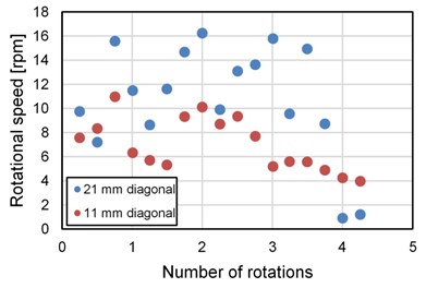
Fig. 5Rotational speed of the stent motor with hole
4. Stent motors having a cross receiver
4.1. New stent motor design
The receivers used for stent motors are more suitable if they are large in area. However, it is not possible to attach receivers larger than the diameter of a blood vessel. Therefore, we conceived of a shape in which a receiver is placed within a coil and extends in the direction of the rotational axis. In addition, we proposed combining two plates into a cross shape, thus providing a width in the direction in which ultrasound vibrations are received while simultaneously increasing area. Fig. 6 shows a manufactured stent. We combined two rectangular stainless steel plates 20 mm in length, 8 mm in width, and 0.05 mm in thickness with their corners cut off to form right triangle shapes with 2 mm bases and 5 mm in height.
4.2. Manufacturing simulated blood vessel blocks used in experiments
In the experiments here, we considered selecting and using a material closer to blood vessels than the resin block used in the previous section. Teflon is used in artificial blood vessels. However, here we used a gel (Exseal Corporation, Asker C15 Human Skin Gel) considering the fact that it is easily obtainable, has a modulus of elasticity close to that of actual blood vessels, and can be freely molded into any shape. The modulus of elasticity of human blood vessels is as shown in Fig. 7 [3]. The modulus of elasticity of the human skin gel used here was 0.51 MPa, which is believed to be suitable for a human blood vessel substitute. To ascertain the optimal diameter for a simulated blood vessel for use in experiments, we manufactured a block using human skin gel providing holes, altering the diameter every 1 mm from 11.3 mm to 11.7 mm.
Fig. 6Stent motor with cross receiver
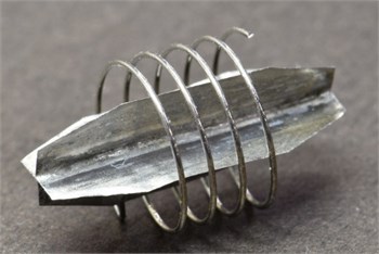
Fig. 7Elastic modulus of blood vessel[4]
![Elastic modulus of blood vessel[4]](https://static-01.extrica.com/articles/20908/20908-img7.jpg)
4.3. Experiments with stator windings and blood vessel inner diameter
4.3.1. Experimental method
To examine the effect of the number of stator windings on the rotational phenomena, we manufactured multiple stators, by altering the number of windings in contact with the inner vascular walls by 0.5 windings from 3 windings to 7 windings. In addition, as dimension errors would arise during manufacturing, we manufactured three specimens of each stent motor design. We placed a simulated blood vessel block in a water bath and arranged a stent motor within it. We set the horn of the homogenizer immediately above this. The water depth was 110 mm, the immersed horn length was 20 mm, and the height from the bottom of the water bath to the bottom of the simulated blood vessel block was 60 mm. We set the ultrasonic homogenizer output to 100 % and performed ultrasound irradiation for one minute. We performed this three times for each stent motor manufactured. We then filmed their condition with a video camera, measured the number of rotations in one minute based upon these images, and recorded them per 1/8 rotations.
4.3.2. Experimental results
Table 3 shows the average value of the number of rotations per experiment for each simulated blood vessel block diameter. In this table, the results of rotation experiments performed with each simulated blood vessel block for each inner diameter, that is, nine types of numbers of windings, and three specimens of each design, or a total of 27, were all used as data. From the table, we observe that the most rotations occurred when the inner diameter of the simulated blood vessel block was 11.6 mm. It is believed that the number of rotations was less with smaller inner diameters because the pressing force was excessive, and the frictional force hindered rotations. In addition, sufficient frictional force could not be achieved with large diameters, and the contact between the stator and the inner walls of the simulated blood vessel block was unstable, and thus, the rotational force decreased. Fig. 8 shows the results of the experiments with the simulated blood vessel blocks having an inner diameter of 11.6 mm with the horizontal axis representing the number of stator windings. We observe that the stent motors having stators with 4.5 windings rotated the most. In addition, we can confirm that the number of rotations greatly decreases when the number of windings is six or more. This is believed to be because vibration damping occurs for longer stators, and hence, ends far away from the receiver do not vibrate. This indicates that driving power is not generated, and friction hinders rotations.
It is believed that, when conducting experiments by changing the other conditions, a simulated vessel block inner diameter of 11.6 mm and the number of stator windings of 4.5, which are the conditions showing the most rotations, may be adopted.
Fig. 8Number of rotations (11.6 mm diameter block)
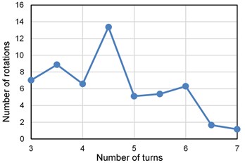
Table 3Average number of rotations
Inner diameter of block [mm] | Average number of rotation |
11.3 | 1.23 |
11.4 | 2.77 |
11.5 | 3.14 |
11.6 | 6.16 |
11.7 | 1.58 |
5. Experiments on receiver size
5.1. Experimental method
Regarding the effects of the receiver size used for a stent motor on the rotational speed, we manufactured three specimens of each stent motor design, by varying the receiver length by 5 mm from 10 mm to 35 mm, to verify the newly designed cross receiver. In addition, the number of coil windings was set to 4.5. Fig. 9 shows a stent motor. The coil length of the receivers exceeding 35 mm stopped at a large width, and there was a high possibility of contact with the inner vascular walls. It was believed that this was not realistic, and hence, no manufacturing was performed here. For each stent motor, we performed ultrasound vibration irradiation experiments under the same conditions as in Section 5.3.1 and filmed them with a video camera.
5.2. Experimental results
Fig. 10 shows the measurement results. Furthermore, it shows the average of nine data obtained for each dimension as results. From the figure, we observe that a stent motor having a receiver 20 mm in length rotates the most. It is believed that the low number of rotations of stent motors having shorter receivers was because they are unable to receive sufficient ultrasound vibrations as a result of decreased area. In addition, as for stent motors having receivers 25 mm or longer with a decreased number of rotations regardless of large area, cross receivers in parallel with the direction of ultrasound irradiation did not receive ultrasound vibrations, and conversely the moment of inertia increased, making rotation difficult.
5.3. Correlation of distance from ultrasound vibration source and the number of rotations
5.3.1. Experimental method
Regarding the distance between the stent motor and the source of vibration, we separated the tip of the ultrasonic homogenizer from the stent by 10 mm increments and we performed one-minute ultrasound irradiation 10 times at each position. The length by which the tip of the horn was immersed in water was fixed at 20 mm, and hence, we raised the water depth every time we raised the position of the horn.
5.3.2. Experimental results
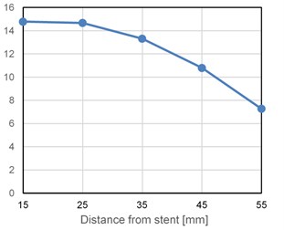
Fig. 11 shows the measurement results. We averaged the results for each condition and listed them. From the graph, we observe that the number of rotations decreased as the distance of the stent motor from the horn, which was the source of vibration, increased. In addition, if the horizontal axis is and the vertical axis is then it is possible to approximate –0.0060.210 12.95 by a quadratic function. We observed that ultrasound vibrations scattered in a spherical shape dampen according to the inverse square law. It is believed that the results obtained roughly correspond to this law.
Fig. 9Stent motor with different sized receivers
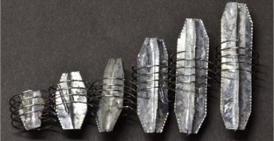
Fig. 10Number of rotations of stent robot with different sized receivers
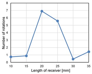
Fig. 11Number of rotations of stent motor when the distance from the horn is changed
6. Conclusions
We manufactured a stent motor in a shape that can be inserted into a blood vessel and has a receiver unlikely to obstruct blood flow and confirmed that it rotates from ultrasound vibrations within a simulated blood vessel. In addition, we observed that its rotational speed is affected by the blood vessel inner diameter, the number of stator windings, and the receiver size.
Usually, stents are inserted into a blood vessel while in a contracted state and have a structure that expands near the affected sites. Therefore, a future objective is the design of an ultrasound motor with a structure that expands and contracts while maintaining performance. This function could be applied for adjusting the frictional force between a stator and the inner vascular walls. In addition, reproduction of other human body tissues such as fat and bone, and verifying how ultrasound vibrations propagate or dampen, is required.
References
-
Nishizawa U., Toyama S. Development of active stent moving by ultrasonic vibration. Vibroengineering Procedia, Vol. 13, 2017, p. 205-210.
-
Takesue N., Ohara T., Ishibashi R., Toyama S., Hoshina M., Hirai Y., Fukaya N., Arata J., Fujimoto H. Position control methods of spherical ultrasonic motor. Proceedings of IEEE/RSJ International Conference on Intelligent Robots and Systems, 2010, p. 3061-3066.
-
Moriya T., Furukawa Y., Akano Y., Nakajima A. Experimental Study on a Miniature Ultrasonic Motor Using a Coiled Stator. IECEI Technical Report, No. US2005-29, 2005, p. 41-45.
-
Hasegawa H., Kanai H., Hoshimiya N., Chubachi N., Koiwa Y. Accuracy evaluation in the measurement of a small change in the thickness of arterial walls and the measurement of elasticity of the human carotid artery. Japanese Journal of Applied Physics, Vol. 37, 1998, p. 3101-3105.
About this article

