Abstract
A multi-dimensional lumbar traction treatment bed is designed with two degrees of freedom, which can realize controllable traction treatment of lumbar through flexion, extension and rotation motion. Two linear actuators are used to provide motion. Building a mathematical model of the device by least squares identification. PID controller and Kalman filter constitute two groups of control modes: (i) speed control; (ii) position control. Using MATLAB to perform simulation experiments. The results show that the designed controller can achieve high control accuracy. The motion speed of lumbar platform is stable and the position of traction treatment set by user is approached exactly, which ensuring the security and stability of this device.
1. Introduction
Sedentary and sports injuries in modern people are leading to a younger lumbar disease trend [1]. In addition to the elderly, teenagers under the age of 18 also have a risk of disease [2]. Non-surgical treatments are thought to achieve effective therapeutic effects in the early stages of the illness. Traction is a common method of conservative treatment for lumbar disease. Several studies show that the swing traction therapy facilitated the patient's improvement in pain and relieve the lumbar disease [3-5]. What's more, the effect of multi-directional traction is probably superior to that of longitudinal traction in improving the symptoms and clinical findings of patients with lumbar disc herniation [6].
Compared with surgical treatment, traction therapy won't destroy the intervertebral disc. The risk of this method is much lower. Therefore, most patients will prefer such conservative treatment. Many medical device companies have committed to the study of traction beds. Lojer from Finland has designed Manuthera 242 [7]. This device use the traction, flexion, lateral flexion and rotation of table to treat the key positions of patient. However, Manuthera 242 is purely manual. Hill Laboratories has produced AIRFLEX [8], which can provide both manual and motorized flexion. But this kind of production can only realize limited freedom. None of the above devices have achieved precise control of traction speed and position.
The multi-dimensional lumbar traction treatment bed presented in this paper has two degrees of freedom, which can realize controllable traction treatment of lumbar through flexion, extension and rotation motion. Six-axis motion attitude sensor is used to evaluate the speed and position of lumbar platform. The position controller allows the platform to reach the set position stably and safely. Speed controller keeps the platform speed near the set speed during steady motion.
2. Design
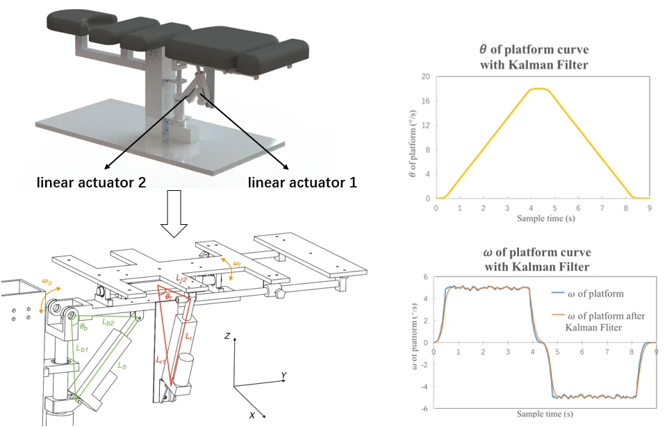
The design goal of the lumbar traction treatment bed is to provide controlled motion in selected spine portions. In order to achieve the above functions, this device includes a buckling and extending component and a rotating component as shown in Fig. 1. Both components use linear actuator as the active member to form a linkage mechanism which provides controlled motion of lumbar platform. The linear actuator has a peak speed of 20 mm/s. The stroke length is 100 mm. A six-axis motion attitude sensor is placed below the platform which is used to feedback the current position and speed. The speed and position signal is sent to the control borad. The motor of linear actuator is driven at 24 V using a 20 kHz PWM signal through driver.
Fig. 13-D model of traction treatment bed
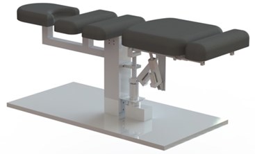
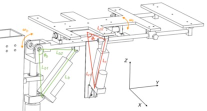
Fig. 2Parameterization of platform without mattress
3. Modeling
3.1. Motion model
As shown in Fig. 2, the device implements flexion, extension and rotation motion trough two crank-and-slide mechanisms in series. When the patient is lying down, the axis is the coronal axis and the axis is the vertical axis. The subscript indicates the buckling and extending component with swing around . The subscript r indicates the rotating component which swing around . is the distance between the rotating joint of platform and the bottom mounting position of linear actuator. is the distance between the rotating joint of platform and the top mounting position of linear actuator. the current length of linear actuator. is the current position of platform. is the current speed of platform.
For current length :
where means the initial installation distance of linear actuator. means the current stroke of linear actuator.
From the triangle cosine theorem, there are:
where , are constants. is the initial angle of platform in the horizontal position.
Eq. (2) derives the time. Obtain the platform angular velocity :
In order to make the traction motion smooth, the angular velocity of platform should be kept as constant as possible to improve patient comfort.
3.2. System model of the linear actuator
The principle of a linear actuator is that after DC motor is geared down, the screw nut converts the motor rotational motion into the linear motion. It is known that the transfer function between DC motor speed and voltage.:
where is the motor potential coefficient. is the mechanical time constant. is the electrical time constant. From Eq. (4) and the formula of linear actuator, it can be deduced that the transfer function between the speed and voltage of linear actuator is:
where is the screw lead and is the gear reduction ratio. Deduced from Eq. (5), the transfer function between the linear actuator stroke and the voltage is:
When building a system model, the traditional method is to calculate the specific parameters using empirical formulas. However, the transfer function obtained through this method will course a large error. Therefore, the direct identification method [9] is used to estimate the transfer function parameters. The transfer function of linear actuators is second-order no-lag according to Eq. (5). The model is:
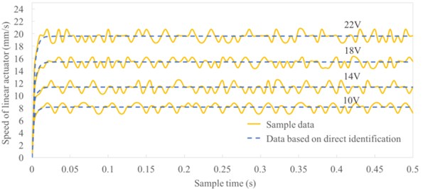
Since , approximate . The problem translates into solving , and . Add 10 V, 14 V, 18 V, 22 V step voltage to the linear actuators. The Hall sensor is used to obtain the speed of the linear actuators. The speed in 0-5s is sampled at a sampling frequency of 100 Hz. 500 points were totally sampled. Using least squares method to identify the transfer function. Obtain that 0.0052, 0.0237, 0.8913. Simulating the speed-time curve by using Matlab. Fig. 3. Since the simulation results are similar to the sample data, the transfer function is accurate.
Fig. 3Step response curve of linear actuator based on direct identification
4. Controller
The control system designed in this paper implements two control modes: (i) speed control; (ii) position control. A six-axis motion attitude sensor is used to detect the current position and speed of platform. PID controller features short transients and high stability. Both control modes designed in this paper use PID control.
4.1. Speed control
The control structure of speed control is shown in Fig. 4. Speed control is enabled when the platform accelerates to the set speed . The error is the difference between set speed and actual speed . These errors are caused by external disturbances of the driver and measurement noise of the sensor. To obtain an accurate speed signal, the Kalman filter is used before feedback. The PID controller generates a PWM signal which drives the linear actuator and adjusts the controller gain. The formula of PID model is:
4.2. Position control
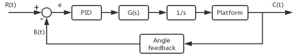
The control structure of speed control is shown in Fig. 5. Position control is used during the acceleration phase and deceleration phase. The set position of platform is , and the current position is . At the start-up phase, position control is used to acceleration stability. Disable the position control and enable the speed control when the set speed is reached. When it’s 1° away from the distance setting position , disable the speed control and enable the position control. Slow down the platform until set position is reached.
Fig. 4The PID control structure for speed control
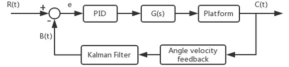
Fig. 5The PID control structure for position control
5. Simulation
Taking the extension motion as an example, the motion of one period is: Firstly, the linear actuator in the buckling and extending component is pushed out to swing the platform upward. When the setting position is reached, the linear actuator is driven to contract. The platform swing downward until return to the initial position.
For experiment, the limit position of platform is set to +18°, and the angular velocity is set to ±5°/s. An experimental system was built in Matlab using the mathematical model described in Section 3. Adjust the PID parameters to obtain the experimental results are shown in Fig. 6.
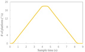
Thereafter, introducing Gaussian white noise into the controller and sensor. Obtain position-time curve and speed-time curve of platform without using the Kalman filter as shown in Fig. 7. Finally, the Kalman filter is added. Adjust the parameters of Kalman filter to obtain the experimental results under this condition which shown in Fig. 8.
Fig. 6Simulation results in ideal status
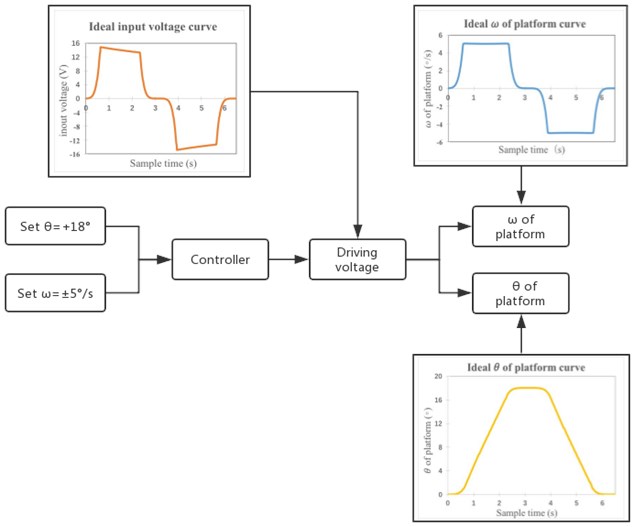
Fig. 7Simulation results without Kalman filter
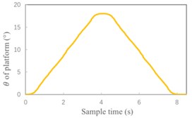
a) Position-time curve of platform
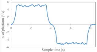
b) Speed-time curve of platform
Fig. 8Simulation results with Kalman filter
a) Position-time curve of platform
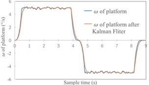
b) Speed-time curve of platform
6. Analysis of experimental results
Analyze the error of experimental results. As shown in Table 1, using the Kalman filter can significantly improve the accuracy of speed control. Speed error reduced from 0.063 % to 0.037 %. For position control, the actual limit position is more approach to set position after using Kalman filter. What's more, the position-time curve is smoother.
Thereafter, simulation experiment of flexion, clockwise rotation and counter-clockwise rotation is performed. The error of each group of motion is shown in Table 2. Analyze Table 1 and Table 2. The designed controller can achieve high control accuracy. The motion speed of platform is stable and the position of traction treatment set by user is approached exactly.
Table 1The error of platform in extension motion
Experimental condition | The limit 𝜃 of platform (°) | Error of 𝜃 (%) | 𝜔 of platform (°/s) | Error of 𝜔 (%) |
Without Kalman filter | 17.998 | 0.011 | 5±0.317 | 0.063 |
With Kalman filter | 17.999 | 0.006 | 5±0.184 | 0.037 |
Table 2The error of platform in other three motion
Motion | The limit 𝜃 of platform (°) | Error of 𝜃 (%) | 𝜔 of platform (°/s) | Error of 𝜔 (%) |
Flexion | 17.999 | 0.006 | 5±0.208 | 0.042 |
Clockwise rotation | 17.999 | 0.006 | 5±0.253 | 0.051 |
Counter-clockwise rotation | 17.999 | 0.006 | 5±0.172 | 0.034 |
7. Conclusions
This paper presents a multi-dimensional lumbar traction treatment bed which provides flexion, extension, clockwise rotation and counter-clockwise rotation motion. Each treatment motion is controllable. Two linear actuators are used to provide motion. PID controller and Kalman filter constitute two groups of control modes: (i) speed control; (ii) position control. The simulation experiments are based on the mathematical model of this device. Experimental results show that the designed controller has good performance and achieve precise control, which ensuring the safety and stability of this device. In further studies, the efficacy of the device in actual spinal diseases should be tested.
References
-
Klang E., et al. Prevalence and awareness of sacroiliac joint alterations on lumbar spine CT in low back pain patients younger than 40 years. Acta Radiologica, Vol. 58, Issue 4, 2016, p. 449-455.
-
Durham S. R., Sun P. P., Sutton L. N. Surgically treated lumbar disc disease in the pediatric population: an outcome study. Journal of Neurosurgery: Spine, Vol. 92, Issue 1, 2000, p. 1-6.
-
Pin X., et al. Biomechanical effects of different traction modes on lumbar spine. Journal of Medical Biomechanics, Vol. 29, Issue 5, 2014, p. 399-404.
-
Gagne A. R., Hasson S. M. Lumbar extension exercises in conjunction with mechanical traction for the management of a patient with a lumbar herniated disc. Physiotherapy Theory and Practice, Vol. 26, Issue 4, 2010, p. 256-266.
-
Kim H. S., Yun D. H., Huh K. Y. Effect of spinal decompression therapy compared with intermittent mechanical traction in lumbosacral disc herniation. Annals of Rehabilitation Medicine, Vol. 32, Issue 3, 2008, p. 319-323.
-
Zhang Y., Yue S., Yue Y. A comparison between multi-directional mechanical traction and longitudinal traction for treatment of lumbar disc herniation: A randomized clinical trial with parallel-group design. Chinese Journal of Rehabilitation Medicine, Vol. 26, Issue 7, 2011, p. 638-643.
-
Manuthera 242 Mobilisation Table. Lojer, http://www.lojer.com/product/manuthera-242-mobilisation-table
-
Hill AIRFLEX II Flexion & Distraction Table. Hill Laboratories, https://hilllabs.com/chiropractic/Hill-Air-Flex-Table.php.
-
Zhou R. X., Zhang Z., Qi Y. C. Direct identification of DC electromotor model parameter. Computer Simulation, Vol. 23, Issue 6, 2006, p. 31-33.
About this article

