Abstract
A sliding mode control algorithm based on proportional switching function was developed to make the lower limb exoskeleton more fit the human walking gait trajectory. It could improve the comfort of the exoskeleton wearer and enhance the reliability of the system. The three-dimensional mechanical model of the exoskeleton built using software SolidWorks was introduced to ADAMS and then the model parameters were set. The model was combined with the software MATLAB so that the human-machine cooperation control algorithm for lower limb exoskeleton based on ADAMS and Simulink co-simulation was developed. The simulation result was compared with the desired trajectory and the trajectory under PID control. The research discovered that the ability of trajectory tracking under the sliding mode control was much better than that under PID control. It provided an important theoretical basis for the research on human-machine cooperation control algorithm.
1. Introduction
Power-assisted lower limb exoskeleton is a kind of electromechanical device worn by a human operator. It keeps the same motion with the human by acquiring the human gait data in real time. The power-assisted device can reduce the burden on the body, relieve fatigue caused by prolonged weight-bearing walking and increase the walking speed. Lower limb exoskeleton can also help the lower limb disabled maintain balance and walk [1, 2]. It can be widely used in the medical rehabilitation and orthopedic fields [3]. Nowadays, the lower limb exoskeleton has become an international research hotspot in the field of robotics. And the research on human-machine cooperation control algorithm for lower limb exoskeleton is definitely an important part wherein.
The Berkeley Lower Limb Exoskeleton (BLEEX) under the hybrid control [4, 5] was researched and developed by the University of California, Berkeley’s Human Engineering and Robotics Laboratory. While the human is in the standing posture, the device adopts the position control. While the human is in running condition, the sensitivity amplification control is used correspondingly. The motion and posture are judged by the plantar pressure sensors. The data from the sensors could be collected into massive data sets [6, 7]. Thus, the robustness of the control system can be ensured. The Hybrid Assistive Limb (HAL) [8] developed in Tsukuba University of Japan is controlled by two control methods: CAC and CVC [9-11]. However, because this kind of control method is relied on the relatively weak EMG (electromyogram) signals, it is difficult to achieve precise control. The control method of the Ekso designed by Ekso Bionics adopts gyroscope installed on the device to measure the body displacement track, and then takes the corresponding action. In order to simulate the normal gait of human body, Germany LoKoHelp company developed a kind of power-assisted equipment called LoKoHelp under the control of computer and gait simulation algorithm. What’s more, Netherlands’ LOPES, New Zealand’s REX, and Japan’s Honda’s Stride Management Assist Device also researched the control methods for lower limb exoskeleton. Additionally, the swarm intelligence [12] was also used in the control of lower limb exoskeleton.
Fig. 1Lower limb power-assisted device
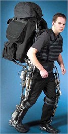
a) BLEEX
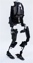
b) Ekso
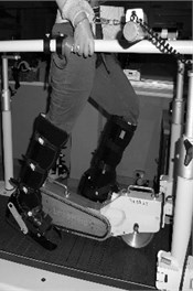
c) LoKoHelp
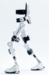
d) HAL
We proposed a new human-machine cooperation control algorithm, called the proportional switching function sliding mode control, for lower limb exoskeleton. Furthermore, the control algorithm was tested and verified with experiments using ADAMS-Simulink co-simulation. Sliding mode control (SMC) has a simple structure and strong robustness against the outside interference. Thus, SMC is widely used in the intelligent control in many fields. In order to verify the accuracy of the control methods and conduct the optimal design of mechanical structure, we used ADAMS and MATLAB to realize a co-simulation for lower limb exoskeleton. SMC for lower limb exoskeleton was used in Simulink and two software interfaces was set. With the strong modeling and simulation function, Adams is often used in dynamic and kinematic analysis. MATLAB has powerful calculating function, high programming efficiency and modular modeling. The combination of these two software can play the advantages of both, which can achieve the integration of mechanical and electrical simulation. Finally, the experimental results were analyzed and compared with traditional control methods. What’s more, wearing experiments and stability testing were also carried out. The results indicate that SMC can provide sufficient driving force to assist wearers, and compared with traditional control algorithm for lower limb exoskeleton, SMC has better accuracy and real-time characteristics.
2. Related works
Sliding mode control is a kind of variable structure control algorithm, the characteristic of which is the discontinuity; and not affected by system parameters or external disturbances. The basic idea of sliding mode control is to find a hyperplane in the error system so that all state trajectories in the hyperplane could converge to zero. The first variable structure controller for robotic control was proposed by Young. By forcing the system into the sliding mode, the controller eliminated the nonlinear coupling between the joints. It can effectively handle the robot’s vertex adjustment problem. Slotine and Sastry applied the variable structure control to the robot’s time-varying trajectory tracking. It was used to conclude the sliding-mode control law based on the rigid manipulators with two degrees of freedom [13, 14].
ADAMS/Simulink co-simulation was widely used in the research on the control over the mechanical and electrical devices in order to make better and further research on the accuracy of the control algorithm and dynamic characteristics of mechanical devices. The method, which established vehicle model in ADAMS and control algorithm in MATLAB/Simulink, was used in the research on the control of vehicles such as ABS (Anti-lock Brake System), TCS (Traction Control System) and ESP (Electronic Stability Program).
3. Sliding mode control
In the nineteen fifties, some scholars proposed variable structure control, and with more than sixty years of evolution and development, a relatively independent research field has gradually formed. Linear and nonlinear system, lumped parameter and distributed parameter system, centralized control and decentralized control, continuous and discrete systems, deterministic and non-deterministic systems, etc., have adopted SMC more and more [15]. SMC is an important part of the variable-structure control. Its typical control characteristic is discontinuity, allowing the robot system to do high-frequency small-amplitude fluctuations in the particular locus. Therefore, realizing the sliding mode control is the key to this algorithm and it is important to ensure that the system is not affected by system parameters or external disturbances. The basic problem of sliding mode control is to determine the sliding surface function or switching surface, i.e., function in a nonlinear system, and to design the control function or control law:
As shown in Fig. 2, sliding mode control’s switching surface is , so there are three types of representative points in the switching surface.
Fig. 2Three kinds of representative points on switching surface
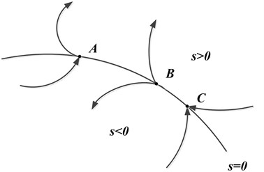
Representative point A: It is usually called the usual point. When it reaches the vicinity of the switching surface, it will pass through from one side to the other side directly.
Representative point B: It is usually called the initial point. The points will move from the vicinity of the switching surface to both sides of the surface.
Representative point C: It is usually called the termination point. When these points reach the vicinity of the switching surface, they will move from both sides of surface to the vicinity of the switching surface.
In the sliding mode control, A and B representative points make no sense in the control algorithm, and the termination point is required. When the representative point reaches the vicinity of the switching surface, it is expected to be attracted to the switching surface and fluctuate. Thus, the representative point becomes a termination point in this region which is the sliding mode region. As for any nonlinear system, the sliding mode region can be shown as , , . In the control algorithm, the system is required to reach the switch point within limited time.
The key to the algorithm is the establishment of the sliding mode. Because of the variety of sliding mode control strategies, the way to realize the system’s reachability is not the same. The mathematical expression of the sliding mode is:
Even if the initial point is not in the vicinity of but anywhere in the state space, the system is also required to move to the switch point. Thus, following accessibility conditions must be met:
(1) Differentiable.
(2) Passing the origin, namely .
In order to ensure finite time arriving and avoid progressive approaching, the condition of reaching can be expressed as:
, can be arbitrarily small. The Eq. (3) is usually expressed as the Lyapunov function:
In this paper, a kind of proportional switching control is adopted. Position signal is and the position error and velocity error of the system are set as a state variables:
The state equation of the system is:
The switching function is:
The control law is:
The invariance of sliding mode can achieve the goal that the sliding mode is completely unrelated to external disturbances and parameter perturbations. It has fast response and performs pretty well in the control of nonlinear system. Therefore, the sliding mode control algorithm is widely used in the industrial intelligent control.
4. ADAMS and Simulink co-simulation
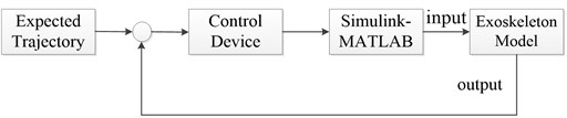
Since the model established in ADAMS is rather rough, so we established three-dimensional exoskeleton model in SolidWorks and then introduced it into ADAMS in which we set the model material, color and conducted module Boolean operations to realize maximum degree of authenticity of the virtual prototype. ADAMS generates the model parameters and motion parameters. They are introduced to Simulink where the sliding mode control algorithm based on proportional switching function is established. Then the control parameters are transferred to ADAMS where the lower limb exoskeleton’s moving characteristics can be clearly observed with the control of SMC. The system simulation diagram is shown in Fig. 3.
Fig. 3System simulation diagram
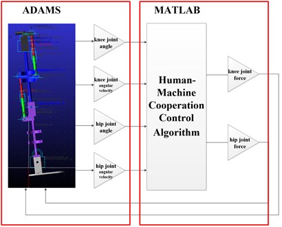
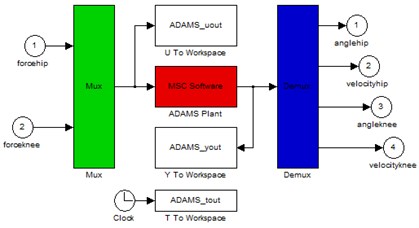
The three-dimensional dynamics model of the exoskeleton is established in ADAMS which will provide four parameters of exoskeleton and then is imported to MATLAB. The control algorithm in MATLAB generates hip and knee control signals which will be finally transferred to ADAMS. Thereby, ADAMS/Simulink co-simulation is realized. The Simulation diagram is shown in Fig. 4.
Fig. 4Simulation diagram
4.1. The establishment of the exoskeleton in ADAMS
The virtual model should be introduced to ADAMS where the material of the model, the degree of freedom, the kinematic pair as well as the input and output parameters are set together. What’s more, the interface to Simulink should also be set. ADAMS and Simulink should have the same default route, which ensures that two software can share data with each other.
The input and output variables need to be set for knee joint and hip joint of lower limb exoskeleton respectively [16]. Each joint requires two output variables, namely the joint angle and joint angular velocity. Each joint requires an input variable, and the thrust is generated by pusher motor. AZ function is used to set the output variable joint angle. Then, joint’s rotation angle around the axis is sent back. WZ function is used to set the output variable joint angular velocity. Then, joint’s rotation angular velocity around the axis is sent back. Single thrust component should be added to the motor putter of the knee and hip joints, which is realized by VARVAL function that connects input variable with single thrust component together.
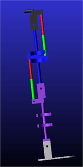
The lower limb exoskeleton model with set parameters is shown in Fig. 5.
Fig. 5Exoskeleton model in software ADAMS
4.2. The establishment of the algorithm model in Simulink
Enter the command ‘ADAMS sys’ in MATLAB, the sub subsystem and ADAMS sys system were obtained, as shown in Fig. 6.
Fig. 6a) Sub system and b) ADAMS system
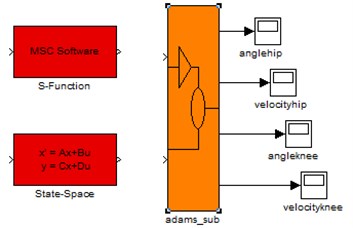
a)
b)
According to Fig. 6, ADAMS sub module of the sliding mode control algorithm based on proportional switching function contains nonlinear ADAMS model, namely containing kinetic calculation model. The sliding mode control law is . Then, set joint angular produced by knee joint and hip joint of the lower limb exoskeleton in control of SMC and transfer the control information to ADAMS sub-module. In this paper, the hip joint trajectory is set as desired input and the ideal condition is that the knee joint can be fixed at 45-degree position.
5. Results and discussions
5.1. Simulation Analysis
In ADAMS, firstly, the initial value should be set: the initial angle of hip joint is 0 degree; the knee joint is 15 degrees; simulation interval is 0.002 s; simulation time is 50 s; the expected position of the hip joint is 30 degrees and the expected position of the knee joint is 45 degrees. The result of simulation analysis is shown in Fig. 7. The results of simulation analysis on the knee and hip joint are shown in Fig. 8 and Fig. 9, respectively.
Fig. 7Simulation of sliding mode control algorithm
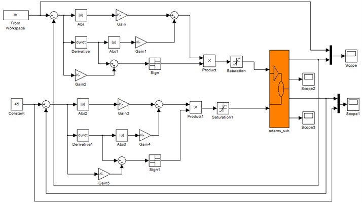
Fig. 8Simulation curve of exoskeleton hip position
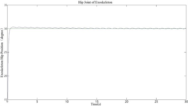
Fig. 9Simulation curve of exoskeleton knee position
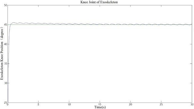
According to the simulation curve, hip and knee joints can reach the expected position at a fast speed, which proves that the system has a fast response speed and great stability. The moving trajectory of the exoskeleton is also shown in ADAMS. We can conclude from the analysis that SMC is suitable for the control of lower limb exoskeleton.
Next, whether the lower limb exoskeleton can simulate the treading track based on the human gait data should be verified [17, 18]. The given walking gait data is used as the input of the control system. The joint moment is used as the input of the module and the motion information of each joint is used as the output feedback. In simulation, the torque variables in the joint co-simulation is called through the function in ADAMS as the driving torque. When the joint movement is driven, the angular and angular velocity values of each joint variable are called into the co-simulation system. With the feedback of the variables, it constitutes a closed-loop control system.
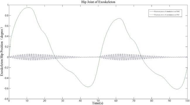
The human gait data are loaded into the workspace of the system using load() function in MATLAB to simulate two kinds of human walking gaits and the simulation time is modified to 100 s. The results of human walking gait simulation are shown in Fig. 10. The positional error in the simulation is shown in Fig. 11.
For comparison, PID control algorithm is also added to the simulation analysis. According to the results of the co-simulation, we can conclude that both control algorithm can coincide with human walking gait curve, but the SMC performs better. The location error can also be controlled within the range of 0.06. However, the simulation curve controlled by PID has significant differences from human walking gait curve. So, the comparison between PID and SMC shows that SMC has better performance in tracking human walking gait trajectory.
In the experiment, combining the strength of both ADMAS and Simulink, the control system of lower limb exoskeleton was established and the stability and dependability of the system were verified. The research method using ADAMS/Simulink co-simulation can shorten design cycle and provide a solid foundation for further research in this field.
Fig. 10Simulation curve of exoskeleton
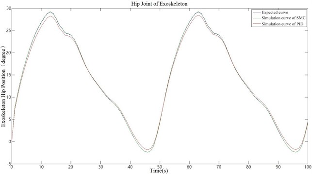
Fig. 11Position error of simulation
5.2. Wearing experiment
In this experiment, all parts of the exoskeleton prototype were made of lightweight aluminum alloy with a total mass of 7 kg, as shown in Fig. 13. According to three testers’ feedback that they can evidently feel the thrust provided by the exoskeleton on their thighs and calves. So, we can arrive at the conclusion that the lower limb exoskeleton designed by us has obvious effort-assist effect for the lower-limb disabled.
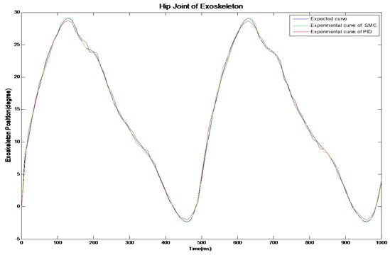
Meanwhile, the comparison experiment was used between the sliding mode control algorithm and the PID control algorithm. In the experiment, two algorithms were used to control the exoskeleton prototype to follow the predetermined human gait trajectory. The encoder recorded the value of the hip joint angle during two walking gait cycles. The hip angle curve is shown in Fig. 12.
It could be seen from the experiment that the experimental results of the system were worse than the simulation results, because the actual system was a highly nonlinear and uncertain system, and the simulation ignored some factors, such as friction and motor viscous. What’s more, the impact of the assembly errors, such as proper alignment, was not taken into consideration. It could be concluded form the maximum overshoot and steady-state accuracy that SMC could still achieve high-precision control and good dynamic quality.
Fig. 12The hip angle curve
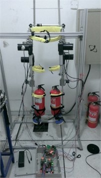
The stability test is shown in Fig. 14. We replaced the human legs with two fire extinguishers weighing 14 pounds each to make repetitive experiments simulating human walking. In this case, the exoskeleton could run for an hour stably.
Fig. 13Wearing experiment
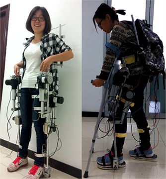
Fig. 14Experiment of stability test
6. Conclusions
In this paper, a sliding mode control algorithm using proportional switching function and based on ADAMS/Simulink co-simulation is introduced and applied to the lower limb exoskeleton. The real-time motion state of the prototype can be obtained and coincides with human walking gaits. Based on the simulation analysis, we can conclude that, in comparison with PID, this sliding mode control algorithm has greatly improved the performance in tracking human walking gaits, which provides a theoretical basis for human-machine cooperation control.
References
-
Bogue R. Exoskeletons and robotic prosthetics: a review of recent developments. Industrial Robot, Vol. 36, Issue 5, 2009, p. 421-427.
-
Na Li, Lei Yan, Hua Qian A design and simulation analysis of an improved lower limb exoskeleton. Journal of Vibroengineering, Vol. 16, Issue 7, 2014, p. 3655-3664.
-
Narong Aphiratsakun, Kittipat Chairungsarpsook, Manukid Parnichkun ZMP based gait Generation of AIT’s Leg Exoskeleton. The 2nd International Conference on Computer and Automation Engineering (ICCAE), 2010.
-
Kazerooni H, Ryan Steger, Lihua Huang. Hybrid control of the Berkeley lower extremity exoskeleton (BLEEX). The International Journal of Robotics Research, Vol. 5, Issue 6, 2006, p. 561-573.
-
Ke Xianxin, Chen Yuliang, Tang Wenbin An overview of the research on the human lower extremity exoskeletons and its key technological analysis. Robot Technique and Application, Vol. 6, 2009, p. 28-32.
-
Zhang Degan, Wang Xiang, Song Xiaodong New medical image fusion approach with coding based on SCD in wireless sensor network. Journal of Electrical Engineering and Technology, Vol. 10, Issue 6, 2015, p. 2384-2392.
-
Zhen Ma New AODV routing method for mobile wireless mesh network (MWMN). Intelligent Automation and Soft Computing, Vol. 22, Issue 3, 2016, p. 431-438.
-
Hayashi T., Kawamoto H., Sankai Y. Control method of robot suit HAL working as operator’s muscle using biological and dynamical information. IEEE/RSJ International Conference on Intelligent Robots and Systems, 2005, p. 3063-3068.
-
Tsukahara A., Kawanishi R., Hasegawa Y. Sit-to-stand and stand-to-sit transfer support for complete paraplegic patients with robot suit HAL. Advanced Robotics, Vol. 24, Issue 11, 2010, p. 1615-1638.
-
Atsushi Tsukahara, Yasuhisa Hasegawa, Yoshiyuki Sankai. Gait support for complete spinal cord injury patient by synchronized leg-swing with HAL. International Conference on Intelligent Robots and Systems, San Francisco, USA, 2011, p. 1737-1742.
-
Suzuki K. Intention-based walking support for paraplegia patients with robot suit HAL. Advanced Robotics, Vol. 21, Issue 12, 2007, p. 1441-1469.
-
Zhang Degan, Wang Xiang, Song Xiaodong A new clustering routing method based on PECE for WSN. EURASIP Journal on Wireless Communications and Networking, Vol. 2015, Issue 162, 2015, p. 1-13.
-
Zhen Ma A novel compressive sensing method based on SVD random measurement matrix in wireless sensor network. Engineering Computations, Vol. 33, Issue 8, 2016, p. 2448-2462.
-
Zhen Ma Shadow detection of moving objects based on multisource information in internet of things. Journal of Experimental and Theoretical Artificial Intelligence, Vol. 29, Issue 3, 2017, p. 649-661.
-
Zhang Degan A new approach and system for attentive mobile learning based on seamless migration. Applied Intelligence, Vol. 36, Issue 1, 2012, p. 75-89.
-
Guojun W., Linhong X., Fulun H. Kinematics Simulation to Manipulator of Welding Robot Based on ADAMS. International Workshop on Intelligent Systems and Applications, 2009, p. 1-4.
-
Yin Maojun Analysis and Design of Wearable Lower Extremity Exoskeleton. Beijing University of Technology, 2010.
-
Li Guang, Zheng Ke An energy-balanced routing method based on forward-aware factor for wireless sensor network. IEEE Transactions on Industrial Informatics, Vol. 10, Issue 1, 2014, p. 766-773.
Cited by
About this article

This research was financially supported by Beijing Higher Education Young Elite Teacher Project (YETP0759) and the Fundamental Research Funds for the Central Universities (Grant No. 2015ZCQ- GX-03).
Hongfang Wu was responsible for study design. Lei Yan was responsible for research methods. Tianyu Jia was responsible for manuscript writing. Na Li was responsible for simulation. Jian Wu was responsible for data collection.
