Abstract
The friction damper has been widely used to reduce the resonant vibration of blades. The harmonic balance method is a well-known method for the linearization of the nonlinear friction force. Meanwhile Mindlin gives analytical expression to describe the nonlinear friction force during stick contact condition, therefore the nonlinear force is represented by two linear coefficients, i.e., equivalent stiffness and equivalent damping. In this work, the stiffness matrix and mass matrix are normalized to a lumped mass and corresponding stiffness according to the definition of stiffness and modal mode. For blades system with underplatform dampers, the dynamic equation for multi lumped mass system is derived and also the iteration method is listed. At last, the experiment verification is conducted using 2 plate blades with underplatform damper. The comparison shows a good agreement in both resonant response and resonant frequency for low normal load cases, and still capture the tendency for high normal load cases.
1. Introduction
The rotor blades in aero-engine are subjected to high dynamic loads caused by fluctuating gas forces resulting in forced vibrations of the blades. The forced vibrations can lead to high cycle fatigue [HCF] failures causing substantial damage and high maintenance effort. Thus, in order to avoid such failures, designers of aircraft engines frequently incorporate friction devices into turbine designs to increase damping and reduce vibratory stresses. This friction devices transmits a load through a friction contact which dissipates energy by micro-slip and macro-slip effects.
The need of reliable prediction for the blades with friction dampers has led to a large number of technical literature and can be grouped to two types: those which emphasize the mathematical aspects of solving systems governed by nonlinear differential equation, e.g., [1-6], and others which are concerned with a specific design application, e.g., [7-11]. In the latter type, Griffin [9] propose a simplest model for the analysis which was a classical single-lumped-mass oscillator. Since it assumed the damper as blade-to-ground type, the damper vibration can not be included. In this paper, multi-lumped-mass for a two-bladed system with underplatform damper is derived and therefore damper mass and damper vibration can be taken into consideration. Verification is conducted by the comparison of numerical prediction and those tested by two plate blades system with underplatform damper. The result shows a good agreement on resonant response and also capture the tendency of resonant frequency shift.
2. Single lumped mass method
The equation of motion for a discrete model of a blade is:
where is the generalized displacement vector and , , represents the mass, viscous damping, and stiffness matrices respectively; is the exciting force vector acting on the blade, and the indicates differentiation with respect to time.
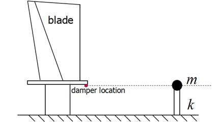
Fig. 1Schematic map of one-dimension model
Suppose that are mass-normalized eigen-vectors of the non-damped linear system, i.e.:
Since this paper will focus on the first mode, the situation in which the system is forced sinusoidally at a frequency near the lowest resonant frequency is considered, however the treatment of higher mode is analogous. It is reasonable to assume that the single lowest mode will dominate and may then be written as:
Substitute Eq. (2) into Eq. (1) and premultiply results in the following differential equation for the first mode of the damped blade:
The physical definition of stiffness means the force that in line with unit displacement. At the same time, the damping effect depends on the relative displacement between damper and blade, thus the eigen-vector should be mode normalized to make the damper location (red solid circle in Fig. 1) displacement unit. The mode normalized eigen-vector can be represented as and Eq. (3) can be represented as:’
where the , and are defined consistent with Eq. (3). Thus the blade system depicted in Fig. 1 can be simplified to a massless cantilever beam with bending stiffness k and a lumped mass m at the cantilever beam tip.
3. Linearized method
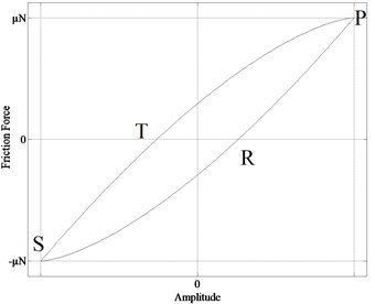
The system with friction dampers can be linearized by fiction model combined with harmonic balance method. For a friction damper the energy dissipated during one cycle of motion is the area enclosed by the hysteresis curve shown in Fig. 2. It is considered as a “micro-macro-slip” model since the energy can be dissipated before gross slip across the interface. Mindlin gives analytical expressions that define the various parts of the hysteresis curves.
Specifically, the nonlinear friction force is given by.
For unloading [PRS in Fig. 2(a)]:
And for cyclic reloading [STP in Fig. 2(a)]:
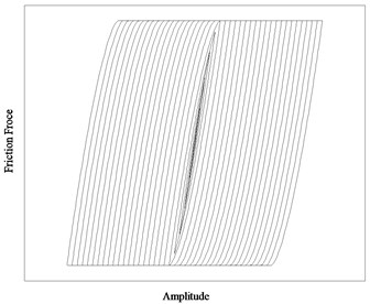
where and , , , represent the relative displacement, friction coefficient, normal force and contact stiffness respectively. This formulas were used to generate the hysteresis curves shown in Fig. 2(b).
Fig. 2Hysteresis from mindlin analysis
a)
b)
The nonlinear friction force can be approximated by a spring and damper acting in parallel, i.e.:
The equivalent stiffness and damping are obtained using the harmonic balance method. It assumes that the displacement is sinusoidal and the nonlinear force has the same period as the motion. Then the force is expanded in a Fourier series and truncated after its fundamental terms that expressed as in phase with motion and out of phase , i.e.:
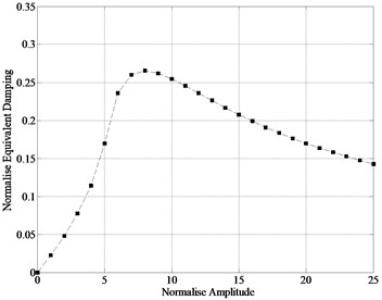
Fig. 3Normalized equivalent damping and equivalent stiffness
a) Equivalent damping
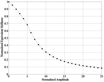
b) Equivalent stiffness
Compare the Eqs. (7) and (8), the in phase term represents spring force and the out of phase term represents damping force. Thus the nonlinear friction force is represented by two linear coefficients. Notice that the relative displacement used for the calculation of nonlinear friction force must be first assumed, so the solution of system response is obtained by the iteration of . The dimensionless equivalent stiffness and equivalent damping of friction force are plotted as a function of relative amplitude in Fig. 3. The horizontal axis is normalized by the distance required to slip, i.e., , and the vertical axis is normalized by the contact stiffness . It is clear that the equivalent stiffness decrease with the increase of relative displacement, and an optimal relative displacement is existed that provides max damping.
4. Multi-lumped mass method
4.1. Derivation of modal equations
Fig. 4 shows the blade system having a underplatform damper and the nonlinear friction force is generated by the relative motion between damper and blades. The blades are simplified to 2 lumped mass and 2 corresponding stiffness by lumped mass method depicted in chapter 2. Meanwhile the nonlinear force can be represented by 2 equivalent coefficients, equivalent damping and equivalent stiffness . Since the damper vibration can not be ignored and the nonlinear forces are generated between the damper and the contact blades, the equivalent stiffness coefficients and equivalent damping coefficients are also separated as left side and right side, subscripts are 1 and 2 respectively. Thus the blades system depicted in Fig. 4 can be represented by only 3 lumped mass 4 springs and 2 damping coefficients, see Fig. 5.
Fig. 4Blade system with underplatform damper
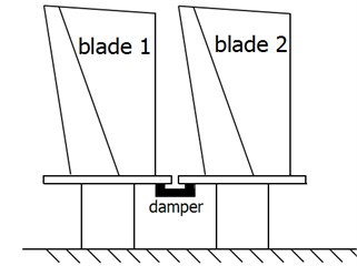
Fig. 5Schematic map of the multi lumped mass model
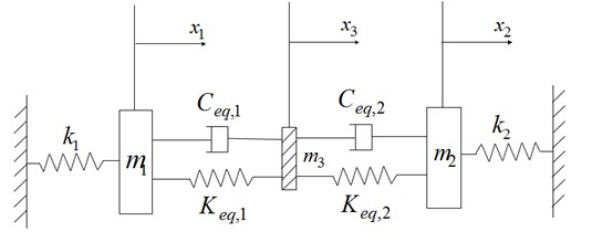
Here mean the damper mass and the kinematic equation of the multi-lumped-mass system can be expressed as follow:
where:
For most blade system, it is reasonable to assume the blades have same geometric characteristic and boundary conditions, thus the bending stiffness and lumped mass obtained by modal mode and frequency are same, i.e., and .
4.2. Experiment verification
In order to verify the numerical prediction using the multi mass method with respect to the experimental results, 2 plate blades system with a underplatform damper system depicted in [12] is analysed.
The nonlinear solution of the 2 plate blades system is performed iteratively with bisection method using the following steps:
1) A guess value of relative displacement that between the damper and the blades is given;
2) The equivalent stiffness coefficients and damping coefficients are calculated based on the Mindlin micro-macro model using single harmonic balance method, then the nonlinear system turns to be a linear system;
3) The relative displacement is computed;
4) The error between the assumptive relative displacement and the computed is calculated to decide whether the iteration has achieved a convergence.
Fig. 6Comparison between test and calculated results
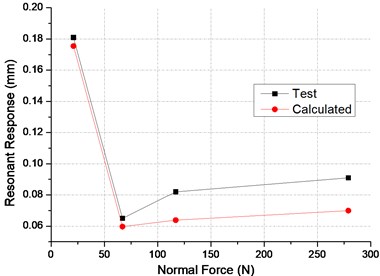
a) Resonant response
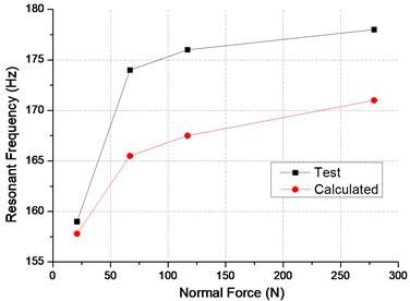
b) Resonant frequency
A comparison of the response predicted by numerical analysis and those measured in [12] are plotted as function of damper normal load in Fig. 6(a). For high normal load cases, predicted resonant response is lower than the test data. However overall, the predicted resonant response curve is in good agreement with the test data. Experimental and numerical values of resonant frequency are portrayed in Fig. 6(b). A obvious frequency difference existed between predicted and tested values, however the numerical data still capture the tendency of the frequency shift on normal load.
Since the lumped mass and bending stiffness are normalized on the modal mode without consideration of damper, the effect of the damper on resonant frequency and modal mode can not be included. The damper reinforce the blades system, thus the bending stiffness increases which is in line with the comparison.
5. Conclusion
In this paper, the blades system with underplatform damper is normalized according to stiffness definition and the modal mode, thus a two blades with underplatform damper is transformed to only a 3 DOFS system. The linearization of the nonlinear system is conducted through the Mindlin micro-macro model and single harmonic balance method. In addition the nonlinear solution of blades system with underplatform damper is achieved by iterating the assumptive relative amplitude.
Numerical predictions were compared to the experimental data, overall in good match in terms of the resonant amplitude. Obvious difference in terms of resonant frequency is observed as the modal mode that used in the normalization process is obtained without damper. However this multi lumped mass method can quickly calculated the response and resonant frequency in a certain accuracy as the dynamic equation is so simple.
References
-
Siewert C., Panning L., Wallaschek J., et al. Multiharmonic forced response analysis of a turbine blading coupled by nonlinear contact forces. Journal of Engineering for Gas Turbines and Power, Vol. 132, Issue 8, 2010, p. 082501.
-
Petrov E. P. A high-accuracy model reduction for analysis of nonlinear vibrations in structures with contact interfaces. Journal of Engineering for Gas Turbines and Power, Vol. 133, Issue 10, 2011, p. 102503.
-
Petrov E. P. Method for direct parametric analysis of nonlinear forced response of bladed discs with friction contact interfaces. Turbo Expo: Power for Land, Sea, and Air, American Society of Mechanical Engineers, 2004, p. 397-408.
-
Petrov E. P., Ewins D. J. Analytical formulation of friction interface elements for analysis of nonlinear multi-harmonic vibrations of bladed discs. Turbo Expo: Power for Land, Sea, and Air, American Society of Mechanical Engineers, 2002, p. 899-908.
-
Petrov E. P. A method for use of cyclic symmetry properties in analysis of nonlinear multiharmonic vibrations of bladed discs. Turbo Expo, collocated with the International Joint Power Generation Conference, American Society of Mechanical Engineers, 2003, p. 235-245.
-
Chen J. J., Yang B. D., Menq C. H. Periodic forced response of structures having three-dimensional frictional constraints. Journal of Sound and Vibration, Vol. 229, Issue 4, 2000, p. 775-792.
-
Szwedowicz J., Sextro W., Visser R., et al. On forced vibration of shrouded turbine blades. Turbo Expo, collocated with the International Joint Power Generation Conference. American Society of Mechanical Engineers, 2003, p. 257-266.
-
Cameron T. M., Griffin J. H., Kielb R. E., et al. An integrated approach for friction damper design. Journal of Vibration and Acoustics, Vol. 112, Issue 2, 1990, p. 75-182.
-
Griffin J. H. Friction damping of resonant stresses in gas turbine engine airfoils. Journal of Engineering for Gas Turbines and Power, Vol. 102, Issue 2, 1980, p. 329-333.
-
Koh K. H., Griffin J. H., Filippi S., et al. Characterization of turbine blade friction dampers. Journal of Engineering for Gas Turbines and Power, Vol. 127, Issue 4, 2005, p. 856-862.
-
Firrone C. M., Zucca S., Gola M. M. The effect of underplatform dampers on the forced response of bladed disks by a coupled static/dynamic harmonic balance method. International Journal of Non-Linear Mechanics, Vol. 46, Issue 2, 2011, p. 363-375.
-
Hao Y., Shan Y., Zhi Z. Effects of platform friction damper on resonant stresses in gas turbine blades. Journal of Aerospace Power, Vol. 16, Issue 1, 2001, p. 55-58.
About this article

