Abstract
The particle damper as a passive means for vibration suppression, is preferred due to its simplicity and easy to implement and control, with no need for any auxiliary power equipment. The bottleneck of the design for the particle damper is that damping performance is influenced by many parameters including particle material and size, packing ratio and cavity dimensions of enclosure such as length, width and diameter. In fact, the overall damping effect of particle damper is closely related to the primary structure system parameters. However, the influences of the excitation point, dampers arrangements, excitation force amplitude, and excitation force type for overall damping effect are scarce reported in the open literatures. How to exert particle damper on the structure and how many particles filled within the cavity, which are needed to face the problem in the engineering practice. In the face of doubt above-mentioned, the above questions will be clarified in this paper. At the same time, an optimization algorithm by the application of genetic algorithms of BP neural network is carried out in order to get most excellent damping effect. These will offer significance guidance to design and conduct particle dampers implement in the specific engineering practice with reference significance.
1. Introduction
Active or passive control techniques are developed to suppress vibrations in mechanical and structural systems or the civil engineering. In practice, passive control is preferred due to its simplicity and easy to implement and control, with no need for any auxiliary power equipment [1]. Currently in engineering field, widely used damping devices include the forms of viscoelastic materials, frictional devices, tuned absorbers, isolators, single unit impact damper (1-DOF or 2-DOF), multi-unit impact damper, bean bag impact damper, resilient impact damper and buffered impact damper, etc. Viscoelastic materials are limited to be used in a certain temperature range but they will lose their effectiveness in low and high temperature ranges or extreme acid and alkali environments [2]. Friction dampers are used for certain high temperature applications, such as in turbine blades. However, their performance disappears with the wearing condition of the sliding surface and future design trend is moving away from assemblies and toward integral parts, eliminating friction interfaces. Tuned absorbers and isolators are only effective in a small frequency range and sensitive to operating condition changes [3]. The single unit impact damper, as referred to impact damper, is an early development passive control device, which takes the form of a freely moving mass, constrained by two stops inside a container or an enclosure mounted on the primary structure. It has been successfully used to vibration attenuation of steam turbine buckets [4], printing cylinders [5], rotating blades [6], vehicles [7], radar antenna [8] and machine tools [9]. However, there are a number of issues that prevent more widespread use of impact damper. One such obstacle is the high level of acceleration caused by collision of the rigid mass with the rigid stops attached to the structure together with the corresponding high noise level, particularly when collisions occur between metal objects. Additionally, the large contact force may cause local damage to the structure of the mass or the stops [10]. Multi-unit impact damper consists of multiple masses instead of a single mass. This produces smaller contact force for each mass while maintaining the same effect of the single unit impact damper, but with a similar overall effect as an equivalent single mass [11]. Masri’s [11] analytical and experimental work showed that the multi-unit particle damper is more efficient than single unit impact damper in reducing noise and vibration. Bean bag damper (BBD) is composed of particles and a resilient plastic bag. A lot of experimental researches about BBD were done [12, 13], which were found that the bean bag impact damper is better than the conventional impact damper in vibration suppression, contact forces reductions, and noise attenuation. Popplewell and Semercigil [14] pointed out that the resilience of the damper could be modified by adjusting the tightness of the flexible bag. This investigation also shows that the performance of the bean bag impact damper is significantly affected by the tightness of the bag, since it is one of the main factors affecting the contact characteristics. As the author stated that, the contact force is the key to the control effect and in turn the key to the design of such an impact damper. Unfortunately, the contact forces cannot be predicted easily and the flexible boundary of the bean bag damper cannot be reasonably modeled for the simulation because they evolve over time and change nonlinearly with the level of the external excitation force. This may prove to be an obstacle to the widespread application of this kind of impact damper. Resilient impact dampers was studied by Chen and Wang where the deformation of the impact damper with the stops during the collision is taken into account [15]. Results showed that the clearance of an effective impact damper for such a freely vibrating system should be smaller than twice of the initial displacement of the main mass of the vibration system and the impact noise was greatly reduced. The important feature to be carried out in the analysis of this model is that the contact time is taken into consideration in the modeling of the behavior so coefficient of restitution models is unsuitable. The buffered impact damper is an extension of the resilient impact damper by introducing a flexible buffer zone between the freely moving damper mass and the stop fixed onto the primary system [10, 16, 17]. The experimental work showed that the buffered impact damper not only significantly reduces the accelerations, contact force and the associated noise generated by a collision but also enhances the level of vibration control by absorbing more of the impact energy and increasing the contact time when the performance of the buffered impact damper is compared with that of a conventional rigid impact damper.
One attractive alternative is particle damper (PD). The particle damper is such a device that the metallic or ceramic particles are placed in an enclosure attached to the vibrating structure [18, 19]. Particle damper is a derivative of single-mass impact damper, which can perform well even in severe environments where traditional passive damping methods such as the use of viscoelastic materials are ineffective. Additional benefits of using granular materials instead of a single mass include the elimination of excessive noise and potential damage to the interior wall of the containing hole. Such an additional damping and mass improve the dynamic response of the primary structure. It offers several advantages due to its conceptual simplicity, potential effectiveness over broad frequency range, temperature and degradation insensitivity, and very low cost [2, 20-24]. Particle damper has been thoroughly studied over the years with a large volume of books and papers in the published literature. Many authors using the lumped mass approach by numerical analysis modeled a bed of particles as a single particle, estimating the performance of the particles damper based upon this equivalent particle [21, 24-29]. Liu et al. [30] estimated the damping contribution of the particles damper as an equivalent linear viscous damping. Particle dynamics simulation, also called Discrete Element Method (DEM), was first developed by Cundall and Strack 30 years ago [31]. There have been considerable researches in the field of particle damping, and some analytical models have been developed [23, 31-38]. It is very regrettable that the application field is only limited to the Single-Degree-of-Freedom (SDOF) system or the equivalent SDOF. More recently, Wu et al. [39] explored a theoretical model based on multiphase flow theory of gas-particle to evaluate the granular particle damping characteristics. Fang and Tang [3] further validated the multiphase flow theory of gas-particle approach based on previous work of Wu et al. [39], and carried out detailed studies where the damping effect due to different energy dissipation mechanisms is quantitatively analyzed. Soon afterwards, Wu et al. [40, 41] carried out detailed studies to the energy dissipation in particle damping where an improved analytical model for particle damping was developed. However, applications in the above literatures have been based on heuristic evaluations of particle damping.
Despite there have been considerable researches in the area of particle damping, and analytical models have been developed, expansion application of particle damping technology and design of the particle damper remain difficult due to a number of problems. One of the principal reasons is that particle damping is a very complicated phenomenon and remarkable nonlinear behavior. The damping properties are subject to many parameters influence including particle material and size, excitation point, packing ration, excitation force and type, and dampers arrangement. The other reason is that most of the modeling efforts have been concentrated in the simplification of the problem in order to figure out these issues where the internal interactions of the particles are not taken into account or the problem is to linearize the model for different operating conditions. In general, these numerous analytical and experimental studies have focused on the SDOF systems or the equivalent SDOF. However, for most structures found in engineering practice, the structure cannot reasonably be approximated as a SDOF system, since the complex external loading and the damper impacts themselves are likely to excite more than just the fundamental mode of vibration. In view of the above-mentioned facts, the factors that affect the damping performances are studied in detail based on extensive experiments in this paper. Our effort is directed towards making an assessment of the parameters above significance from an experimental viewpoint. This in turn provides meaningful guidelines for designing particle damper and applying particle dampers in engineering practice with reference significance.
2. Experiment setup and experiment procedures
2.1. Experiment setup
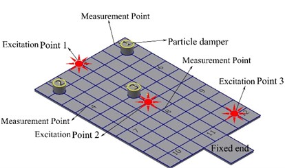
We choose a rectangular plate for this study to evaluate particle-damping performance. The reason is that it is an infinite DOF system as opposed to the single DOF systems usually studied in the literature [2, 14, 19, 21, 22, 24, 42, 43]. When excited by a shaker, the structural response could exhibit a large number of modes. This would allow us to investigate the broadband effect of particle damping. The experimental setup is illustrated in Fig. 1 with a description of measurement instruments used.
Fig. 1Experimental setup figure and schematic diagram of experimental set-up
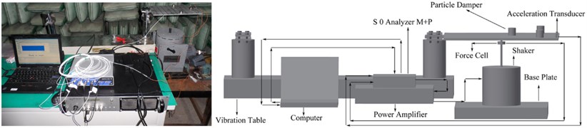
The experimental configurations consist of the primary structure (cantilever rectangular plate) and three aluminums enclosures containing particles. The enclosures partially filled with particles are attached to the plate which is itself attached to an electromagnetic shaker (M B MODAL 50A) providing an excitation force. The signal of the harmonic excitation is amplified by Power Amplifier (M B500VI) to the shaker. The force and acceleration signals are measured with the force transducer (Dytran1051V4) and acceleration transducer (Dytran 3133B1) having a mass of 0.6 g, respectively. A Dynamic Signal Analyzer (M+P SO Analyzer) is used to collect and process the data. The plate is specified with a mass density 2646 kg/m3, Young’s modulus 5.6×10¹⁰ Pa, and Poisson ratio 0.27. The plate dimensions are length 300 mm, width 200 mm, and thickness 6 mm. The mass of the enclosure is 14.52 g and its interior diameter and height are 16 mm and 20 mm, respectively.
2.2. Experiment procedures
Our experiment procedures are as follows:
1. To determine the characteristic of the undamped system, modal characteristic of the rectangular plate without particle damper is analyzed. Key characteristic is the resonant frequencies of the structure. This characteristic will typically be determined through a combination of experimental testing and finite element analysis (FEA).
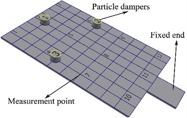
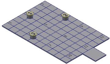
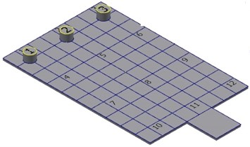
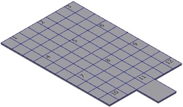
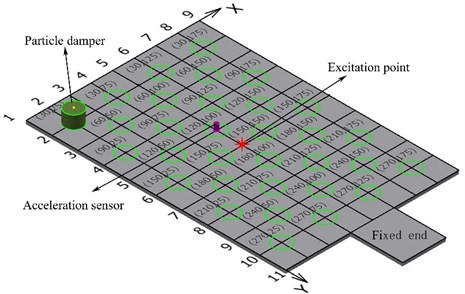
2. To reveal the damping effects of the particle dampers, harmonic excitation is applied to the rectangular plate with a maximum frequency of 1200 Hz, when the solid rectangular plate without particles damper, with three added mass blocks, and with three particle dampers (each the particle damper mass equal to the corresponding mass block). The arrangement location of three particle dampers is indicated in Fig. 2.
3. To gain an appreciation of the important parameters, a series of experiments are designed. Particle material and size, excitation point, packing ratio, excitation force and type, and dampers arrangement are varied. Damping is estimated for each configuration. Trends in the results are studied to determine the influence of the varied parameter.
4. The optimization of the particle damper arrangement by the application of genetic algorithms of BP neural network is carried out.
Fig. 2Arrangement location of particle dampers
3. Experiment results
3.1. Modal characteristics of the rectangular plate
In order to validate the experiment as the baseline system, the first four natural frequencies of the system formed by the rectangular plate without particle dampers are compared with those of the FEA. The structure has natural frequencies at 40.74 Hz, 263.29 Hz, 653.53 Hz and 828.25 Hz for the first four bending modes by the experiment; the natural frequencies by FEM analysis are at 39.06 Hz, 270.31 Hz, 685.94 Hz and 814.06 Hz respectively. The natural frequencies make relatively small changes in the first four mode shapes. Relative errors of the experiment to the FEA do not exceed 4.72 % showing a good agreement between the experiment and the FEA.
3.2. Effects of particle damping
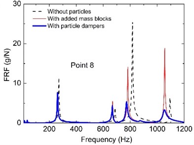
In order to showing effects of particle damping, both force and acceleration of the system versus the frequency of excitation are measured. The frequency response functions (FRFs) acceleration/force of the rectangular plate are successively measured at twelve points of the rectangular plate when the rectangular plate without particles damper, with three added mass blocks, and with three particle dampers (each the particle damper mass with particles equal to the corresponding mass block) as indicated in Fig. 2. The particle damper or the added mass block can be fixed by adhesive to the top of the rectangular plate and can be easily removed and changed. The locations of these nodes are chosen in order to describe adequately the dynamic behavior of the structure in the considered frequency band. In this case, tungsten particles of 0.3 mm in size are partially filled with the aluminum enclosure. The density of the tungsten particle is 17000 kg/m3. The mass of the added mass block 1, 2 and 3 is 26.37 g, 25.47 g and 24.59 g, respectively. The three enclosures include the tungsten particles mass are 32.87 g in all. The rectangular plate mass is 1000 g which represents approximately 30 times the total mass of all particles used in particle dampers.
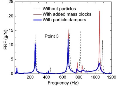
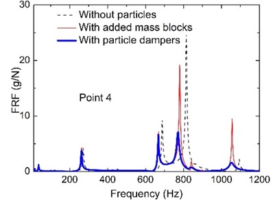
Fig. 3 shows the effect of the added particles in attenuating the frequency response in the broad frequency band. It is shown that the particle dampers have good performance in reducing the response of structures under dynamic loads. Such a strong damping effect has been consistently observed in each measurement point. We observe that the damping performance of the particles is remarkable and extremely high. It can effectively control the fundamental mode of the primary system; the control effect for higher modes is more prominent.
Fig. 3The comparison results of the FRFs on the rectangular plate without particles, with added mass blocks and with particle dampers
a)
b)
c)
It is noted that any three points at the plate are chosen as observing point to display the response of the whole plate typically, which are point 3, 4 and 8 due to symmetry of plate. Further examination of the test data allows us to determine the effects of the system parameters, namely, particle size, excitation point, excitation type and damper arrangement as given in next section. For particle material and volumetric packing ratio, many of the comparative studies have been carried out before. Researchers have reached the consensus that better damping performance is achieved with a particle material of a higher mass density; high packing ratio results in the best vibration attenuation [28, 39, 44]. For excitation force, the FRFs of the plate are used to evaluate the effect of the particle damping, which are the ratio of acceleration amplitude to exciting force on each observing point. So above three parameters is not discussed in this paper.
3.3. The system parameter influence
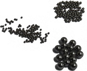
3.3.1. Particle size
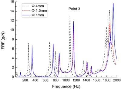
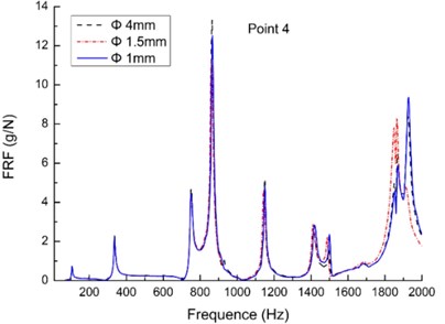
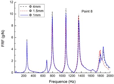
The effect of particle size on damping is evaluated in experiments with miniature bearing steel balls. The bearing steel balls are chosen because many sizes are readily available. Three different sizes are used: 1 mm, 1.5 mm and 4 mm in diameter; they are presented in Fig. 4(d). The particle dampers arrangement is shown in Fig. 2. The RFRs of the three measurement points are also tested in the measurement points 3, 4 and 8, respectively.
Fig. 4Comparison of the FRFs on plate when the dampers are filled with the different dimension sizes particles
a)
b)
c)
d)
The resu1ts are shown in Fig. 4(a) to (c). It is observed that the impact effect of particle size is quite low when the mass packing ratio is 40 % and keeps the same in the each test. Among the three sizes of 1, 1.5 and 4 mm in diameter, the differences in response amplitude are very small, even overlap. Unlike its counterpart for the contact between two large bodies, the internal friction coefficient of a particle assembly is typically higher and is measured using a standard testing procedure in soil mechanics to evaluate the shear force in the interface of two layers of the particles as described in Ref. [45]. The particles of the smallest size of 1 mm should yield more significant damping. However, the smallest bearing steel balls did not provide more damping than the large bearing steel balls. Precise reasons for this effect are not yet understood.
The most useful information from this series of experiments is that the effect of particle size on damping did not go as we have expected that the damping is strongly dependent on the size of particles. It is possible that the strength of the size dependence is in turn dependent upon the material type. In other words, the damping effects of the particle size in the case are not obvious what may be too small for one material may not be for another material.
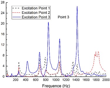
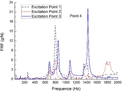
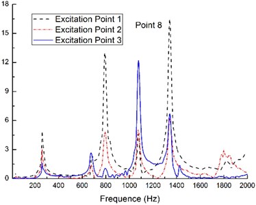
3.3.2. Excitation point
The excitation points are shown in the Fig. 5(d), which are the excitation points 1, 2 and 3. The particle dampers arrangement and the measurement points remain the same (see the Fig. 2). The tungsten power is selected as the filled particle material and the mass packing ratio is taken as 40 %.
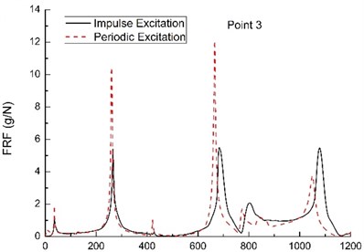
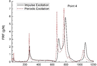
There are clearly something different in the FRFs of the primary structure with three particle dampers from the Fig. 5(a) to (c). The effect of the particle damping is different under the harmonic excitation in the different excitation points when the measurement point keeps same. Its essential factors are resulted from what the excitation point is also input point of the energy, and the area around the excitation point has serious vibration. Various studies conducted over recent years have demonstrated that particle damping phenomena are highly nonlinear, i.e. amplitude dependent.
Fig. 5Comparison of the FRFs on plate when the system is excited at the different points
a)
b)
c)
d)
It is also evident that during the intermediate frequency excitation, i.e., the frequency from 600 to 1600 Hz, the effect of the particle damping under the harmonic excitation in the excitation point 2 is more effective than the other case. This characteristic is obvious in the measurement points 3, 4 and 8 (see the Fig. 5(a) to (c)) by observation FRFs. This is due to the position of the excitation point 2 which coincide with the vibration amplitude peak of the second modal shape when the rectangular plate with three particle dampers is excited within the frequency range above-mentioned. The intense collisions and friction occur between the inter-particles within the enclosure cavity. The particles absorb the kinetic energy of the vibrating structure and convert it into heat through the inelastic collisions and friction.
The results, shown in Fig. 5, demonstrate that the damper efficiency depends on the mode shapes of the plate and the level of the damping increases when the displacement amplitude increases. This result confirms that the relationship between the relative positions of the excitation point and the measurement points should been taken into account when evaluating particle-damping effect.
3.3.3. Excitation type
Impulse excitation (i.e., the free vibration) experiments are carried out by hammer exciting the primary structure. Periodic excitation (i.e., the forced vibration) experiments are conducted using harmonic excitation. The particle selection, mass packing ratio, the particle dampers arrangement and the measurement points still hold the same as those listed above. The excitation point 2 is selected as the excitation point (see the Fig. 5(d)).
Fig. 6Comparison of the FRFs on plate when the system under different excitation types
a)
b)
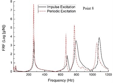
c)
Fig. 6(a) to (c) shows the FRFs of the acceleration response of the primary structure with three particle dampers. It can be seen that the primary structure under hammer exciting provide a high level of attenuation, resulting in slightly better control compared to the case under harmonic excitation. This is due to the damper having to dissipate the constant energy input of the system under periodic excitation as opposed to the transient energy input of the free vibration response under hammer exciting. Based on this experiment, we get that the damping performance is significantly influenced by the type of the excitation.
Again, a similar trend is seen in the results shown in Fig. 6(a) to (c) for forced vibration under harmonic excitation. The frequencies of peak response obviously shift toward the left. In this case, such shift phenomenon is possible due to the connection type between the rectangular plate and the electromagnetic shaker (see the Fig. 1), which are connected by adhesive. It is obvious that the adhesive is an additional constraint condition for boundary conditions of the rectangular plate, which leads to natural frequencies shift.
3.3.4. The damper arrangement
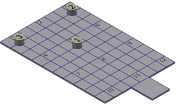
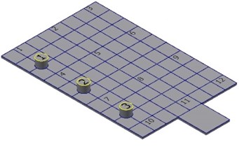
In order to reveal the particle dampers locations on the dynamic response of the rectangular plate, five configurations of the dampers positions are considered (see Fig. 7). The three dampers used in this experiment have the same design parameters. The tungsten power is selected as the filled particle material and the mass packing ratio is taken as 40 %. The dampers are fixed on the rectangular plate according the five configurations described in Fig. 7.
Fig. 7Different arrangement locations of the particle dampers
a) Configuration 1
b) Configuration 2
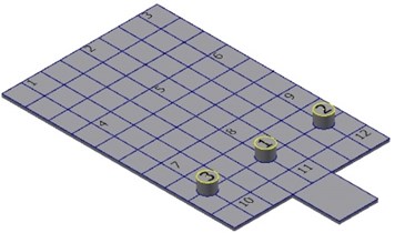
c) Configuration 3
d) Configuration 4
e) Configuration 5
f) Configuration 6
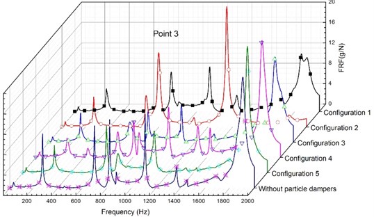
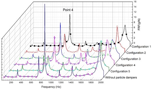
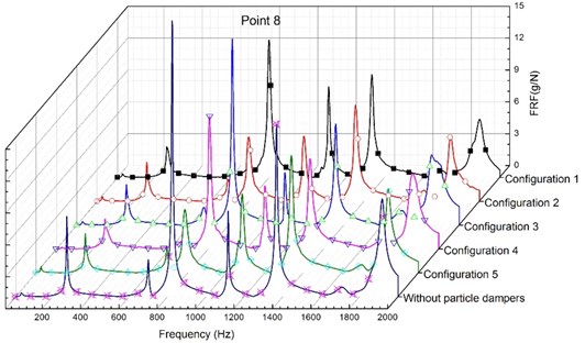
For above situations, Fig. 8 shows the FRFs (acceleration/force) measured for the five configurations at the points 3, 4 and 8. It is noticed that what arrangement configuration of the particle dampers is more efficient in a wide frequency band (from 0 to 2000 Hz) is difficult to be determined when comparing the modal damping of the system for the five configurations. For example, it has been shown in the configuration 2 that it can effectively control the fundamental mode of the primary system; however, the control effect for higher modes is variable.
The results in the Fig. 8(a) show that the rectangular plate without particle dampers controls the structure better than the case the rectangular plate with the three particle dampers for the higher modes in the configuration 2. That is, the particle dampers do not have any effect, even the results more bad. The reason is that the appearance of the particle dampers exerted has influenced the form of the mode shapes of the rectangular plate. The modal damping of the system also becomes surprisingly complicated. Based on the extensive experiments, the results confirm that the damper efficiency depends on the mode shapes of the rectangular plate. When these response data are analyzed, we can draw a problem that how much damping can be reasonably expected from what type of the particle dampers arrangement. The question about the optimization of the particle dampers arrangement for suppression of vibrations needs further study.
Fig. 8Comparison of the FRFs when particle dampers are located on different configurations
a)
b)
c)
4. Optimization of damper location based on genetic algorithms of BP neural network
Damping performance of the particle damper is closely related with the large number of parameters, such as the dimension and material of the enclosure, the shape and material of particles, the amount of free space (gap size or volume fraction) given to the particles, the placement position of the particle dampers and the level of displacement and acceleration of the primary structure [46]. Researchers have come to the coincident conclusion particle damping has been found to be highly non-linear [3, 21, 39, 47]. In order to obtain the optimum damping effect, the different combinations of system parameters above need to be optimized. Theoretical analysis is limited to very simplified systems and one of the current approaches is based on Discrete Element Method. The limitations of discrete element method are computationally intensive due to need to model all the particles in the enclosure [19, 48] which may be of the order of tens of thousands in practice.
Simonian think that as far as forced vibration to be concerned, the resulting damping performance depends on particle size (PZ), packing ratio (PR), Particle density (PD) and placement position of the particle damper (PP) [22]. In forced vibration applications, there is an optimal selection for the different combinations of system parameters aforementioned. Only considering a single factor, brute force methods (full sorting) may be available, however full sorting is not competent for so many parameters above or many inputs and many outputs. We follow the principle from simple to complex, from easy to difficult for factors being considered. We only consider a single factor (placement position of the particle damper) in this paper as an attempt to valid this novel method based on genetic algorithms of BP neural network for estimation of damping effect. Of course, further work is needed to analytically and experimentally model their behavioral characteristics for the different combinations of system parameters (PZ, PR, PD and PP) in our next work.
The experiments are carried out with different combinations of system parameters (PZ, PR, PD and PP) for the estimation of damping effect. For the sake of the convenience for comparative analysis, the peak values of the frequency response functions (FRFs) acceleration/force of the rectangular plate with particle damper are used to describe damping effect for first three order modal. The minimum value of the FRFs (MV) is set as extremal optimization for the each order modal, which characterizes the system with better damping effect.
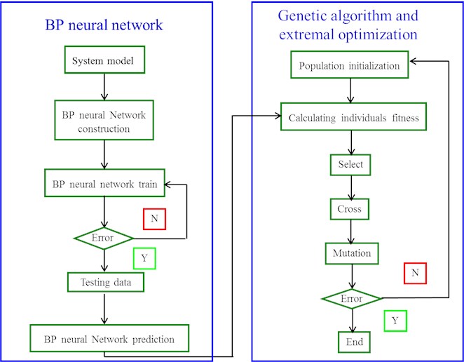
In order to obtain the relationship between system parameters (PZ, PR, PD and PP) and frequency response functions (FRFs) based on extensive experiment data, in fact, this is a mapping technique with many inputs (PZ, PR, PD and PP) and one output (MV). Neural networks (NN) with back propagation learning are a kind of multilayer feed forward neural networks, which can realize arbitrary nonlinear mapping from input to output and it has been used in various engineering. However, the choice of the basic parameter (network topology, learning rate, initial weights) often already determines the success of the training process. The selection of these parameters follow in practical use rules of thumb, but their value is at most arguable. The problem of the neural networks is that a number of parameters have to be set before any training can begin. However, there are no clear rules how to set these parameters. Yet these parameters determine the success of the training. Genetic algorithm (GA), as a set of global optimistic search algorithm, can search in multiple regions of solution space at the same time, and is able to jump from local optimum and get the global optimum based on principles like selection, crossover and mutation [49]. The genetic algorithm may overcome the above problem and is used to find these parameters for optimization of the weights of neural network. The number of neurons in network and placement to the layers has big influence over effectivity of whole system. Designed network from standpoint of topology, we can use GA for design of suitable network configuration.
The idea of combining GA and NN came up first in the late 80s, and it has received great acclaim in the computer science research community since the 1980s. A broad variety of problems have been investigated by GANN approach [50, 51]. Meanwhile, the optimization of the weight and threshold of matrix by the application of genetic algorithms of BP neural network can improve the prediction precision [52]. Neural networks and genetic algorithms demonstrate powerful problem solving ability. They are based on quite simple principles, but take advantage of their mathematical nature: non-linear iteration.
Fig. 9Particle damper exerted positions and coordinates
This section examines how genetic algorithms with neural networks can be used to optimize the exerted position of the particle damper, which enables us to get a broad view on current research. In this section, for the sake of brevity, here one particle damper is considered as an attempt. The tungsten power is selected as the filled particle material and the mass packing ratio is taken as 60 %. The positions of the excitation point and measurement point are shown in the Fig. 9. The primary system with one particle damper is excited under the harmonic excitation. The position coordinates of the particle damper is (from 0 to 200 mm) and (from 0 to 300 mm) respectively, which is treated as the input units (see Fig. 9).
The exerted positions of the particle damper are 32 groups in all. The peak values of the frequency response functions (FRFs) acceleration/force of the rectangular plate with particle damper are shown in Table 1 for first three order modal, which are treated as the output units. An initial population of individuals is created. The minimum value of the FRFs is set as extremal optimization for the each order modal, which characterizes the system with better damping effect. The network has two inputs and with one output FRFs. In this problem, there are two input units and one output result, so the network may adopt the 2-5-1 structure, where 2 is the number of neurons in input layer, 5 is the number of neurons in hidden layer and 1 is the number of neurons in output layer in the following experiment.
Supposed the number of samples is 32. Thirty samples are used to training the 2-5-1, while two samples are used to test generalization ability. The number of neurons in network and placement to the layers has big influence over effectivity of whole system. Designed network from standpoint of topology, we can use GA for design of suitable network configuration. The classical view on programming can be illustrated in the Fig. 10.
The classical genetic algorithm (GA) architecture is as follows (see Fig. 11). Firstly, we create a population of individuals (chromosomes) randomly. In this study, we only consider a single factor (placement position of the particle damper), so there are two parameters (horizontal coordinate of the particle damper), (vertical coordinate of the particle damper). We use binary coding and chromosome length is 2. The fitness or every member of the current population are computed using proportional fitness assignment. If an individual in the current population meets the requirements then stop, otherwise run the algorithm for another generation. Secondly, roulette wheel selection is used to extract members from the current population for creating the next generation. Thirdly, single point crossover and single point mutation are applied for crossover and mutation to the selected individuals to generate a new population. These individuals reproduce to form new individuals (solutions) with fitter ‘parents’ producing more children on average, than less fit individual. The algorithm proceeds, until the desired criterion is met; a solution, which, falls within precision required, or a set number of generations being completed.
It is noteworthy that there are four key parameters in basic genetic algorithm procedure, which are population quantity (), evolutional generation (), crossover probability () and mutation probability (). These values should be set in advance before the run of the genetic algorithm.
The effectiveness and good quality of solution is found to depend on the above-mentioned four operation parameters of genetic algorithm. However, there is no clear theoretical basis given as to how to define the values of the , , and . This means that their value is at most arguable. In the practical application of genetic algorithm, the selection of these parameters follow in practical use rules of thumb. In general, is set from 20 to 100; is set from 100 to 500; is set from 0.4 to 0.99; is set from 0.0001 to 0.1. In this study, the values of the , , and are set as 20, 100, 0.2 and 0.05 respectively.
Fig. 10Classical computer programming
Of course, with the improvement of genetic algorithm, some new improvement approach maybe overcome the above problem such as adaptive genetic algorithm, niche generic algorithm, annealing evolution algorithm, cross generational elitist selection, heterogeneous recombination, cataclysmic mutation.
Table 1Optimization coordinate results of the particle damper
Mode shapes | Fitness | Optimal coordinate (mm) |
First order modal | 0.7084 | (30.22, 25.58) |
Second order modal | 0.4374 | (159.60, 166.78) |
Third order modal | 0.3339 | (266.54, 25.14) |
The output optimization results of the particle damper are shown in the Table 1. It indicates that if the damping of the primary system with one particle damper wants to get better effect, the particle damper should be exerted at (30.22, 25.58) when the primary system is excited in the first order modal. It is the same in the other two cases, for the second order modal the particle damper should be exerted at (159.60, 166.78) and for the third order modal the particle damper should be exerted at (266.54, 25.14). It can be seen in Table 2 from the experimental results that if the system wants to get a better damping effect, the particle damper should be exerted at (30, 25), (150, 175) and (275, 25), respectively when the primary system with the particle damper is excited in the first three order modal.
It has been shown that the output optimization results are already very close to the coordinate value obtained from the experiment by comparing the Table 1 with Table 2. It also demonstrates that this method based on genetic algorithms of BP neural network provides guidance in implementation process for the optimization of damper location. It can be lay a theoretical foundation for the low noise and low vibration optimization design of equipments or products having the form of structure of particle damping composite construction in industrial practice. However further research is being carried out the optimization of exerted location for multi-particle dampers with different mass packing ratios in order to meet the actual requirements in industrial practice.
Fig. 11The classical genetic algorithm (GA) architecture
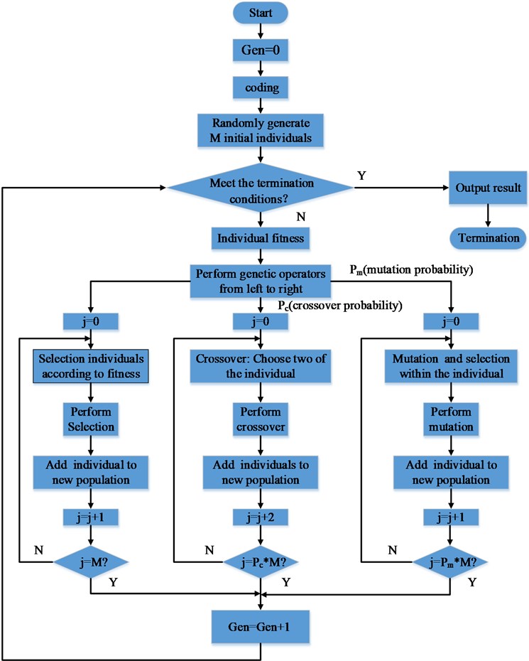
Table 2Peak values of the frequency response functions for first three order modal
Particle damper code | Particle damper coordinate (mm) | First order modal (FRFs: [g/N]) | Second order modal (FRFs: [g/N]) | Third order modal (FRFs: [g/N]) |
2-2 | (30,25) | 0.5462 | 3.6557 | 6.2466 |
2-4 | (30,75) | 0.5667 | 2.8556 | 5.3249 |
2-6 | (30,125) | 0.5848 | 2.8962 | 5.6505 |
2-8 | (30,175) | 0.5967 | 3.4053 | 6.2085 |
3-3 | (60,50) | 0.7246 | 4.6935 | 6.6684 |
3-5 | (60,100) | 0.6751 | 4.5594 | 6.4588 |
3-7 | (60,150) | 0.7633 | 4.7437 | 6.1839 |
4-2 | (90,25) | 0.7100 | 4.0790 | 4.4285 |
4-4 | (90,75) | 0.6888 | 4.2957 | 5.2249 |
4-6 | (90,125) | 0.6689 | 4.2118 | 4.5253 |
4-8 | (90,175) | 0.6893 | 4.0258 | 4.7255 |
5-3 | (120,50) | 0.8319 | 3.4292 | 5.2201 |
5-5 | (120,100) | 0.7692 | 3.5589 | 5.6217 |
5-7 | (120,150) | 0.7996 | 3.4072 | 5.3654 |
6-2 | (150,25) | 0.7126 | 2.3801 | 6.2997 |
6-4 | (150,75) | 0.7262 | 2.6892 | 5.9819 |
6-6 | (150,125) | 0.6630 | 2.7657 | 6.2003 |
6-8 | (150,175) | 0.6663 | 2.1926 | 6.6745 |
7-3 | (180,50) | 0.7946 | 2.4347 | 7.8415 |
7-5 | (180,100) | 0.8047 | 3.0260 | 7.7318 |
7-7 | (180,150) | 0.7935 | 2.5160 | 6.9289 |
8-2 | (210,25) | 0.7251 | 2.4090 | 5.2870 |
8-4 | (210,75) | 0.7063 | 2.8372 | 6.3126 |
8-6 | (210,125) | 0.7088 | 2.9121 | 6.6166 |
8-8 | (210,175) | 0.7274 | 2.4832 | 5.5068 |
9-3 | (240,50) | 0.7740 | 3.3340 | 5.4487 |
9-5 | (240,100) | 0.8183 | 4.1590 | 7.4977 |
9-7 | (240,150) | 0.7858 | 3.2874 | 5.1316 |
10-2 | (270,25) | 0.7508 | 3.8606 | 3.0122 |
10-4 | (30,25) | 0.5462 | 3.6557 | 6.2466 |
10-6 | (30,75) | 0.5667 | 2.8556 | 5.3249 |
10-8 | (30,125) | 0.5848 | 2.8962 | 5.6505 |
5. Concluding remarks
The work reported in this paper aims at finding ways to better characterize the particle damping. In this paper, we perform systematic experimental investigation of the effects of a rectangular plate with the particle dampers in detail. The efficiency of the particle damper is examined by comparing the frequency response of the system in the presence of the dampers with the frequency response of the system in the absence of the dampers. It is found that the particle damper not only significantly reduces the accelerations, contact force and the associated noise generated by a collision but also enhances the level of vibration control. Although it is nonlinear, a strong rate of energy dissipation is achieved within a broadband range.
The influence of particle size, excitation point, excitation force type, and dampers arrangement are investigated experimentally. These studies reveal several significant trends in the performance of particle damping. In the experiments, three different sizes of bearing ball are also tested. The bigger particles do not provided more damping than the smallest particles demonstrating independence on size. The likely cause is that there is dependence between particle size and material. This behavior is also likely to be a function of the cavity shape, which needs further study. The relative effects of several parameters on the performance of particle damping are given. It can be seen that for maximum efficiency of the dampers, the level of the excitation has to be high enough to overcome the internal friction between the particles. The effect of damping is shown to be a strong function of amplitude. The dependence is shown in every series of tests. Damping generally increases as the kinetic energy provided to the partic1es increases. High response levels mean more collisions between the particles themselves and the cavity wall. The test series of the five arrangement configurations show that the dampers exerted location has very important influence for damping effect. The optimal location of the particle dampers is an imperative issue.
The results of the experiments discussed above can be used to optimally design particle dampers for a structure that is excited harmonically. Meanwhile, the optimization of the particle damper exerted location by the application of genetic algorithms of BP neural network is carried out. Using the method discussed above, a procedure for the optimum arrangement of particle damper can be developed in engineering practice with reference significance. In addition, by generalizing the experimental results, guideline needs further study for the optimum design of particle dampers. The reason is that a divergence from the optimum range makes the damper inefficient.
Despite all these efforts, numerous questions remain to be answered to understand the nonlinear characteristics of particle dampers under dynamic loads. There are many shortcomings in the experimental setup, which should be resolved in any additional testing. In future experiments, some different combinatorial tests will be used. Another limitation is the inability to change the size of the enclosure cavities.
References
-
Gharib M., Ghani S. A novel impact damper consisting of a linear chain of particles. ASME International Mechanical Engineering Congress and Exposition, Houston, Texas, 2012.
-
Hollkamp J. J., Gordon R. W. Experiments with particle damping. 5th Annual International Symposium on Smart Structures and Materials, San Diego, CA, 1998.
-
Fang X., Tang J. Granular damping in forced vibration: qualitative and quantitative analyses. Journal of Vibration and Acoustics, Vol. 128, Issue 4, 2006, p. 489-500.
-
Paget A. L. Vibration in steam turbine buckets and damping by impacts. Engineering, Vol. 143, 1937, p. 305-307.
-
Bain L. J. Impact Damping of Printing Cylinders. Patent 4.125.073, 1978.
-
Duffy K. P., Brown G. V., Bagley R. L. Self-Tuning Impact Damper for Rotating Blades. Patent 6.827.551, 2004.
-
Prottengeier E., Siegner H. Reversible Impact Damper, in Particular for Vehicles. Patent 5.181.589, 1993.
-
Rocke R. D., Masri S. F. Application of a single-unit impact damper to an antenna structure. Shock and Vibration Bulletin, Vol. 39, Issue 4, 1969, p. 1-10.
-
Sadek M. M. Impact dampers for controlling vibration in machine-tools. Machinery and Production Engineering, Vol. 120, Issue 3090, 1972, p. 152-161.
-
Li K., Darby A. P. An experimental investigation into the use of a buffered impact damper. Journal of Sound and Vibration, Vol. 291, Issue 3, 2006, p. 844-860.
-
Masri S. F. Analytical and experimental studies of multiple-unit impact dampers. The Journal of the Acoustical Society of America, Vol. 45, Issue 5, 1969, p. 1111-1117.
-
Pang C., Popplewell N., Semercigil S. E. An overview of a bean bag damper’s effectiveness. Journal of Sound and Vibration, Vol. 133, Issue 2, 1989, p. 359-363.
-
Liu A. Q, et al. The effective design of bean bag as a vibroimpact damper. Shock and Vibration, Vol. 7, Issue 6, 2000, p. 343-354.
-
Popplewell N., Semercigil S. E. Performance of the bean bag impact damper for a sinusoidal external force. Journal of Sound and Vibration, Vol. 133, Issue 2, 1989, p. 193-223.
-
Cheng C. C., Wang J. Y. Free vibration analysis of a resilient impact damper. International Journal of Mechanical Sciences, Vol. 45, Issue 4, 2003, p. 589-604.
-
Li K., Darby A. P. A buffered impact damper for multi-degree-of-freedom structural control. Earthquake Engineering and Structural Dynamics, Vol. 37, Issue 13, 2008, p. 1491-1510.
-
Kuinian L., Darby A. P. Modelling a buffered impact damper system using a spring-damper model of impact. Structural Control and Health Monitoring, Vol. 16, Issue 3, 2009, p. 287-302.
-
Fricke J. R. Lodengraf damping: An advanced vibration damping technology. SV Sound and Vibration, Vol. 34, Issue 7, 2000, p. 22-27.
-
Chen T., et al. Dissipation mechanisms of non-obstructive particle damping using discrete element method. Proceedings of SPIE International Symposium on Smart Structures and Materials, Newport, California, 2001.
-
Panossian H. V. Structural damping enhancement via non-obstructive particle damping technique. Journal of Vibration and Acoustics, Vol. 114, Issue 1, 1992, p. 101-105.
-
Friend R. D., Kinra V. K. Particle impact damping. Journal of Sound and Vibration, Vol. 233, Issue 1, 2000, p. 93-118.
-
Simonian S. S. Particle beam damper. Society of Photo-Optical Instrumentation Engineers (SPIE) Conference Series, San Diego, California, 1995.
-
Bryce L. F., Eric M. F., Steven E. O. Effectiveness and predictability of particle damping. SPIE’s 7th Annual International Symposium on Smart Structures and Materials, Newport Beach, CA, 2000.
-
Salueña C., Pöschel T., Esipov S. E. Dissipative properties of vibrated granular materials. Physical Review E, Vol. 59, Issue 4, 1999, p. 4422-4425.
-
Masanobu I., et al. Effectiveness of the particle damper with granular materials. 3rd International Conference on Integrity, Reliability and Failure, Porto, Portugal, 2009.
-
Isao Y., Yoshito T., So N. Y. Particle damping with granular materials for multi-body system. ICSV 15 Internation Congress on Sound and Vibration, Daejeon, Korea, 2008.
-
Trigui M., et al. An experimental study of a multi-particle impact damper. Proceedings of the Institution of Mechanical Engineers, Part C: Journal of Mechanical Engineering Science, Vol. 223, Issue 9, 2009, p. 2029-2038.
-
Mao K., et al. Simulation and characterization of particle damping in transient vibrations. Journal of Vibration and Acoustics, Vol. 126, Issue 2, 2004, p. 202-211.
-
Lu Z., Lu X., Masri S. F. Studies of the performance of particle dampers under dynamic loads. Journal of Sound and Vibration, Vol. 329, Issue 26, 2010, p.5415-5433.
-
Liu W., Tomlinson G. R., Rongong J. A. The dynamic characterisation of disk geometry particle dampers. Journal of Sound and Vibration, Vol. 280, Issue 3, 2005, p. 849-861.
-
Cundall P. A., Strack O. D L. A discrete numerical model for granular assemblies. Geotechnique, Vol. 29, Issue 1, 1979, p. 47-65.
-
Legeza V. P. Dynamics of vibroprotective systems with roller dampers of low-frequency vibrations. Strength of Materials, Vol. 36, Issue 2, 2004, p. 185-194.
-
Zhou H., Chen Q. Verifications of the damping properties of particle dampers. Proceedings of the Third Asian Conference on Multibody Dynamics, Tokyo, Japan, 2006.
-
Cundall P. A., Strack O. D. L. The development of constitutive laws for soil using the distinct element method. Numerical Methods in Geomechanics, Vol. 1, 1979, p. 289-317.
-
Bai X.-M., et al. Investigation of particle damping mechanism via particle dynamics simulations. Granular Matter, Vol. 11, Issue 6, 2009, p. 417-429.
-
Bryce L. F., Eric M. F., Steven E. O. Design methodology for particle damping. SPIE’s 8th Annual International Symposium on Smart Structures and Materials, Newport Beach, CA, 2001.
-
Saeki M. Analytical study of multi-particle damping. Journal of Sound and Vibration, Vol. 281, Issue 3, 2005, p. 1133-1144.
-
Wong C. X., Daniel M. C., Rongong J. A. Energy dissipation prediction of particle dampers. Journal of Sound and Vibration, Vol. 319, Issue 1, 2009, p. 91-118.
-
Wu C. J., Liao W. H., Wang M. Y. Modeling of granular particle damping using multiphase flow theory of gas-particle. Journal of Vibration and Acoustics, Vol. 126, Issue 2, 2004, p. 196-201.
-
Wu C. J., Yang R. C., Wang D. Q. An improved of granular particle damping using multiphase flow theory of gas-particle. 20th International Congress on Sound and Vibration, Bangkok, Thailand, 2013.
-
Wu C., Yang R., Wang D. Prediction on vibration response of a cantilever particle-damping beam based on two-phase flow theory of gas-particle. Jixie Gongcheng Xuebao (Chinese Journal of Mechanical Engineering), Vol. 49, Issue 10, 2013, p. 53-61.
-
Papalou A., Masri S. F. An experimental investigation of particle dampers under harmonic excitation. Journal of Vibration and Control, Vol. 4, Issue 4, 1998, p. 361-379.
-
Bryce L., Fowlera E. M. F., Steven E. Olsonb Effectiveness and Predictability of Particle Damping. Proceedings of SPIE 3989, Smart Structures and Materials: Damping and Isolation, 2000.
-
Mao K., et al. DEM simulation of particle damping. Powder Technology, Vol. 142, Issue 2, 2004, p. 154-165.
-
Epstein N., et al. Handbook of Powder Science and Technology. Chapman & Hall, New York, 1997.
-
Trigui M., Foltete E., Bouhaddi N. Prediction of the dynamic response of a plate treated by particle impact damper. Proceedings of the Institution of Mechanical Engineers, Part C: Journal of Mechanical Engineering Science, Vol. 228, Issue 5, 2014, p. 799-814.
-
Xu Z., Wang M. Y., Chen T. Particle damping for passive vibration suppression: numerical modelling and experimental investigation. Journal of Sound and Vibration, Vol. 279, Issue 3, 2005, p. 1097-1120.
-
Wang M. Y., et al. Efficient computation of particle motions in discrete element modeling of particle damping. Proceedings of 8th International Symposium on Plasticity and Impact Mechanics New Delhi, India, 2003.
-
Sexton R. S., Dorsey R. E., Johnson J. D. Optimization of neural networks: a comparative analysis of the genetic algorithm and simulated annealing. European Journal of Operational Research, Vol. 114, Issue 3, 1999, p. 589-601.
-
Koehn P. Combining genetic algorithms and neural networks: the encoding problem. Citeseer, 1994.
-
Zhou Zhi-Hua, et al. Genetic algorithm based selective neural network ensemble. Proceedings of the 17th International Joint Conference on Artificial Intelligence, Seattle, WA, 2001.
-
Weihong Z., Shunqing X. Optimization of BP neural network classifier using genetic algorithm. Intelligence Computation and Evolutionary Computation, Vol. 180, 2013, p. 599-605.
About this article

The work described in this paper was supported by NSFC (Natural Science Foundation of China) Project No. 51075316 and Program for Changjiang Scholars and Innovative Research Team in University (PCSIRT).
