Abstract
In the Paper, models of a bypass graft with a cylindrical and conical cuff and a model of a blood vessel that enable investigating the influence of various geometrical parameters of the cuff upon hemodynamics were developed. Simulation of blood flow and blood pressure in a bypass graft was performed upon applying ANSYS program package based on the finite element method. The influence of the geometrical parameters of a bypass graft with a cuff of different shapes upon the structure of blood flow and development of pathogenesis of the blood vessel was found. It was also found that the best results are obtained when the cuff of the bypass graft is cylindrical and the ratio of the diameter and the height of the cuff is 1.25 and 1.5. If a cuff with such parameters is chosen, hemodynamics will be improved and haemostasia will be avoided, thus reducing a risk of appearance of thrombi in the bypass graft and the blood vessel as well as IH formation and extending the period of bypass patency.
1. Introduction
Cardiovascular diseases remain one of the most frequent causes of death both in Lithuania and worldwidely. One of the key diseases caused by reduction of the opening of coronary blood vessel is atherosclerosis that, in its turn, may cause myocardial infarction. There are various ways of treatment of diseases of the cardiovascular system, including stenting, angioplasty and so on. However, they are not applicable in presence of a bypass graft, i.e. a formed new way for blood flow for blood supply to the heart. Most frequently, an autologous femoral vein bypass graft is used; however, it is not applicable when synthetic bypass grafts, such as polytetrafluoroethylene (PTFE), polyurethane (PU) or Dacron, are used [1]. However, it is known that thrombi appear in bypass grafts within the first year after the surgery operation in about 25 % of cases and within the period up to ten years after the surgery operation – in 50 % of cases [2]. Opinions on failures of bypass graft surgery vary. It may be caused by biomechanical factors [3]; however, according to general opinion, intimal hyperplasia (IH) and neointimal hyperplasia (NIH) are formed because of the peculiarities of the local hemodynamics [4]. In addition, some scientists emphasize the contribution of geometrical parameters to a failure of bypass graft surgery [3]. The connection angle of the bypass graft and the blood vessel may be 20°, 30°, 45°, 60° and 90° [2]. In addition, three ways of anastomosis are available: „end-to-end“, „end-to-side“ and „side-to-side“ [3, 9, 14]. In a majority of points of arteries, blood flowing is laminar. However, if the blood-vessel’s diameter and the angle increase suddenly, sudden flow separation, recirculation and flow stagnation take place. It is supposed in this respect that hemodynamic forces are interrelated and affect IH formation. However, the geometrical shape of the bypass graft may affect IH formation and the disease progression as well.
Digital simulation is an ideal tool for a detailed examination of various parameters that influence IH formation [8, 12-15]. In scientific literature, the connection angle of the bypass graft equal to 20°, 45° and 60° is most frequently discussed upon [2, 3]. 20° connection angle is the minimum angle possible to make by a surgeon [15]. Scientists found that when the connection angle is 45°, the bypass patency is improved and IH formation is reduced [10]. It is supposed that thrombi are more frequently formed in bypass grafts with a larger connection angles, as compared to those with a smaller angle.
In the works [8, 13], a new construction design of a bypass graft with a cylindrical cuff is simulated and preliminary investigation is carried out. The results of the analysis show that the velocity of blood flow at the junction between the bypass graft and the blood vessel depends on the parameters of the cuff.
Digital simulation enables more detailed examination of various parameters in the bypass graft of the blood flow that affect IH and thrombus formation. For optimizing the shape of the bypass graft, the finite element method (FIM), the finite volume method (FVM), the genetic algorithm [5], and artificial neural networks [6] may be applied.
The goal of the research is an assessment of patency of the bypass grafts with cuffs of various shapes and investigation on the influence of geometrical parameters of the bypass grafts with cuffs on hemodynamics and IH formation upon applying the digital simulation method.
2. Methods
Two different models are developed: the first model described the bypass graft with a cylindrical cuff and the second – the bypass graft with a conical cuff. The models of the bypass graft with a cuff and the artery are shown in Fig. 1. The geometry of the model is two-dimensional. The bypass graft and the cuff are autologous. The following assumptions are accepted: walls of the blood vessel do not deform; the velocity at the walls is considered equal to zero thus avoiding the friction; pressure in the end of the model equals to zero. The coronary artery is fully occluded.
Fig. 1The model of a bypass graft with a cylindrical cuff and the artery (a); the model of a bypass graft with a conical cuff (b)
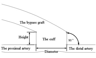
a)
b)
Blood is non-Newtonian isothermal fluid [7, 12]. Blood flow is described by the Navier-Stokes equation upon applying the finite element method [7]:
where is the vectorial velocity of blood flow, m/s, is the pressure, Pa, is the time, s, is the blood density, kg/m3, is the dynamic viscosity of blood, kg/ms.
The Reynolds number is calculated according to the following formula:
where: is the diameter of the artery, mm.
The Reynolds number depends on the inlet velocity and the diameter of the artery. In the input of a cuff, a laminar current is needed to establish the geometrical parameters of bypass grafts that cause turbulence phenomena of the flow. Simulation of blood flow may be carried out individually, if the data of ultrasonic dopplerography in vivo and the results of the blood test of the patient (blood density, blood viscosity) are available. It is accepted in the calculations that blood is Newtonian fluid, blood density 1060 kg/m3, dynamic viscosity of blood 0.0035 kg/ms, blood temperature 37°C. The cardiac rate is 75 beats per minute. Blood flow is impulsive in nature, cycle duration 0.8 s, where 0.4 s – systole, that is blood supply, and 0.4 s – diastole. To describe blood flow patterns sinusoidal law was used [16].
On formation of the model of a blood vessel and a bypass graft with a cuff, it is divided to finite elements upon applying a cycle of 40 iterations (results of repeated use of an operation). For digital simulation and research, ANSYS software was applied.
In the calculations, the ratio between the diameter and the height of the cylindrical cuff () was varied as follows: 8/12 (the ratio 0.6), 12/15 (the ratio 0.8), 12/12 (1.0), 15/12 (1.25), 12/8 (1.5), 17/10 (1.7). The inlet velocity of flow was varied as follows: 1 m/s, 0.5 m/s and 0.1 m/s.
In the model with conical cuff, the conicality of the cuff, i.e. the ratio between the difference of its diameters with its length is varied as follows: 0.16; 0.21; 0.25; 0.3; 0.375 and 0.5.
3. Results
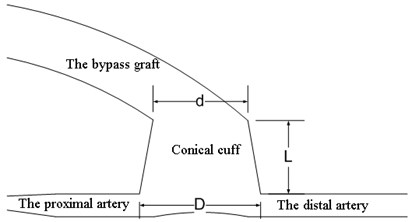
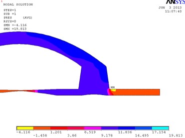
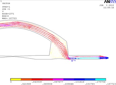
In Fig. 2, the fragments of the obtained results when the ratio between the length and the height of the cylindrical cuff of the bypass graft equals to 1.5 are shown. In the distal outlet, a weak turbulent flow that moves clockwise is formed. In this model, the maximum velocity 1.637 m/s is achieved in the distal outlet. The eddy velocity at the proximal wall of the cuff equals approximately to 0.181 m/s. The velocity in the distal part of the cuff equals to 1.078 m/s. Pressure in the distal part of the cuff equals to 1288 Pa. The maximum pressure in the model is 1827 Pa.
Fig. 2Distribution of pressure in the cylindrical bypass graft (a) and the vectorial velocity of blood flow (b)
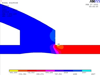
a)
b)
In Fig. 3, the fragments of the obtained results when the cuff is conical and its conicality equals to 0.21 are shown. Pressure is higher at the distal wall of the cuff.
Models of other geometrical parameters were analyzed in an analogous way. The summarized dependencies of pressure on the geometrical parameters of the cuff of the bypass graft and the inlet velocity of the flow are provided in Fig. 4. It may be seen from Fig. 4 that the dependence of blood pressure at the junction of cylindrical or conical cuff and blood vessel on the shape and geometrical parameters of the cuff is nonlinear.
Fig. 3Distribution of pressure in the conical bypass graft (a) and the vectorial velocity of blood flow (b)
a)
b)
Fig. 4The dependence of pressure on the geometrical parameters of the cuff of the bypass graft and the inlet velocity of the flow: in the cylindrical bypass graft (a), in the conical bypass graft (b)
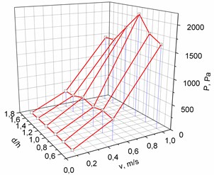
a)
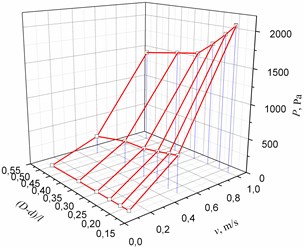
b)
After analysis of the obtained results, it may be stated that the best models are those with uneven distribution of pressure in the distal part of the cuff, i.e. the pressure at the wall is higher as compared to the pressure in the cuff. For example, such case takes place in a conical cuff when the conicality equals to 0.21. In all other models with a conical cuff, the pressure is the same in the cuff. However, when the cuff is cylindrical and ratio equals to 1.25 and 1.5, uneven distribution of pressure in the distal part of the cuff takes place. In such a case, blood flow is laminar, haemostasias are not formed and formation of turbulent flows starts (recirculation). The said factors may extend the period of bypass patency. So it may be stated that the best shape of a cuff is cylindrical.
4. Conclusions
1. The developed computerized model of a blood vessel and a bypass graft with a cuff enables exploring the influence of the geometrical parameters of the bypass graft upon hemodynamics. The model may be usable as an instrument for choosing a suitable shape of a bypass graft and the geometrical parameters in any specific case.
2. The results of the completed analysis show that the velocity of blood flow at the contact of the bypass graft and the blood vessel depends on the shape and the geometrical parameters of the cuff.
3. In course of preliminary research, it was found that the best results are obtained when the cuff is cylindrical and the ratio between the diameter and the height of the cuff equals to 1.25 and 1.5. If a cuff with such parameters is chosen, hemodynamics will be improved and haemostasia will be avoided, thus reducing a risk of appearance of thrombi in the bypass graft and the blood vessel as well as IH formation and extending the period of bypass patency.
References
-
Galdikas J. Kraujagyslių pakaitalai, Vilnius, 1995, p. 115.
-
Grus T., Lindner J., Vik K., Tošovský J., Matěcha J.,Netřebská H., Tůma J., Adamec J. Particle image velocimetry measurement in the model of vascular anastomosis. Prague Medical Report, Vol. 108, Issue 1, 2007, p. 75-86.
-
Jae-Sung Choi, Sung Chul Hong, Hyuck Moon Kwon, Sang-Ho Suh, Jeong Sang Lee Influences of geometric configurations of bypass grafts on hemodynamics in end-to-side anastomosis. The Korean Journal of Thoracic and Cardiovascular Surgery, Vol. 44, 2011, p. 89-98.
-
Dobrin P. B., et al. Mechanical and histology changes in caine vein graft. Journal of Surgical Research, Vol. 44, 1988, p. 259-265.
-
Sousa L. C., Castro C. F., Carlos C. António. Shape optimization of an artificial bypass graft using genetic algorithms. 2nd International Conference on Engineering Optimization, Lisbon, Portugal, 2010.
-
Kamalanand K., Srinivasan S. Modeling of normal and atherosclerotic blood vessels using finite element methods and artificial neural networks. World Academy of Science, Engineering and Technology, Vol. 60, 2011, p. 1314-1317.
-
Thiriet M. Biology and mechanics of blood flows. Part I: Biology. Springer Science+Business Media, 2008, p. 470.
-
Lukšys D., Šešok A. Simulation and analysis of blood flow in bypass grafts with a cuff. Journal of Vibroengineering, Vol. 14, Issue 2, 2012, p. 633-636.
-
Adamec J., Matecha J., Netrebska H., Tuma J. Flow pattern and shear stress distribution in distal end-to-side anastomosis. Acta of Bioengineering and Biomechanics. Vol. 8, Issue 1, 2006, p. 3-12.
-
Giordana S, Sherwin S. J., Peiro J., Doorly D. J., Crane J. S., et al. Local and global geometric influence on steady flow in distal anastomoses of peripheral bypass grafts. Journal of Biomechanical Engineering, Vol. 127, 2005, p. 1087-1098
-
Shalman E., Rosenfeld M., Dgany E., Einav S. Evaluation of the CFR and FFR Paramters by CFD Modeling of the Flow in a Stenosed Coronary Artery. Proceedings of the First Joint BMES/EMBS Conference Serving Humanity, Advancing Technology, 1999, p. 23-28.
-
Mariūnas M., Uzdilaitė G. Blood flow modeling in stenotic carotid arteries with computational fluid dynamics. Journal of Vibroengineering, Vol. 7, Issue 3, 2005, p. 1-4.
-
Henry F. S., Ku Per C., Lewington N. P. Simulation of flow through a miller cuff bypass graft. Computer Methods in Biomechanics and Biomedical Engineering, Vol. 5, Issue 3, 2002, p. 207-217.
-
Shaik E., Hoffmann K. A., Dietiker J. F. Numerical simulations of pulsatile non-Newtonian flow in an end-to-side cuff model. Simulation Modeling Practice and Theory, Vol. 16, 2008, p. 1123-1135.
-
Qiao A., Liu Y. Numerical study of hemodynamics comparison between small and large femoral bypass grafts. Communications in Numerical Methods in Engineering, Vol. 24, 2008, p. 1067-1078.
-
Mariūnas M., Uzdilaitė G. Reserch on the influence of pathology level to stresses in elastic arterines. Journal of Vibroengineering, Vol. 8, Issue 3, 2006, p. 30-34.
About this article

