Abstract
The paper presents the fault diagnosis technique for internal combustion engines using time-frequency representations of vibration signal. Engine block vibration results as a sum of many excitations mainly connected with engine speed and their intensity increases with the appearance of a fault or in case of higher engine elements wearing. In this paper an application of acceleration signals for the estimation of the influence of piston skirt clearance on diesel engine block vibrations has been described. Engine body accelerations registered for three simulated cases representing piston skirt clearance variations were an object of preliminary analysis. The presented procedures were applied to vibration and pressure signals acquired for a 0.5 dm3 Ruggerini, air cooled diesel engine. Reciprocating machines are difficult to diagnose using traditional frequency domain techniques because of generate transient vibration. In conducted experiments wavelet transform has been chosen.
1. Introduction
Piston slap is one of the most characteristic sources of engine body vibrations. Intensity of that excitation and its variations for different engine cycles depends mainly on in-cylinder pressure alterations. Changes of piston slap force value, influencing the piston horizontal movements result also from following factors:
- piston and piston pin mass, connecting rod mass,
- dimensions and the geometry of crank-connecting rod mechanism,
- engine crankshaft angle,
- engine speed and its load,
- piston skirt clearance.
Engine block vibrations result as a sum of many excitations mainly connected with engine speed, and their intensity increases with the appearance of a fault or in case of higher engine elements wearing. There are several fault recognition methods currently in use, they are based on spectrum density analysis both in time and frequency domains, FFT, as well as on wavelet transform and Wigner-Ville transform [1-10]. For the engine block it is important the type of construction and material due to vibroactivity [11, 13, 14].
In this paper, acceleration signals were used to estimate the influence of piston skirt clearance on engine block vibrations. Values of piston slap force, responsible for piston movement, were estimated on the basis of dynamic models of piston-connecting rod mechanism and the in-cylinder pressure variations in the function of engine crank angle. Engine body vibration signal, registered for three simulated cases representing piston skirt clearance variations, was an object of preliminary analysis.
2. Experimental setup
The procedures presented in this paper were applied to vibration and pressure signals from a 0.5 dm3 Ruggerini, air cooled diesel engine.
Test program provided acquisition of the following data:
- in-cylinder pressure,
- vibration signal of engine head and wall, for two directions: and ,
- crankshaft revolution, together with TDC recognition,
- engine torque,
- manifold pressure.
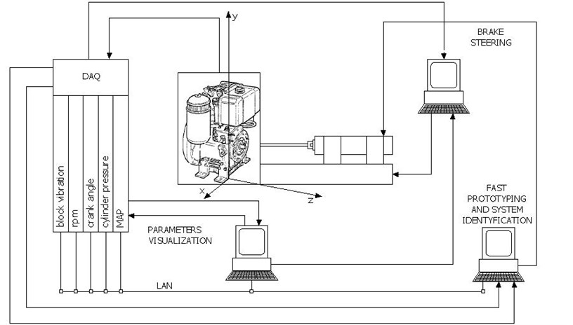
In-cylinder pressure was measured with the use of piezoelectric pressure transducer type 6121 by KISTLER, coupled with charge amplifier model 5011. Crankshaft position and TDC recognition was measured with the use of KISTLER 2613B transducer. Engine body vibrations were measured with ICP sensors by PCB interfacing with PA3000 signal conditioner manufactured by Roga Instruments.
Fig. 1Schematic diagram of experimental setup
3. Analysis of results
The analysis was completed in a way allowing the identification of two characteristic ranges of vibration signal around TDC [12]:
- first range – from 300° to 372° crank angle,
- second from 372° to 420°crank angle.
First range includes information about initiation and running of the combustion process. In the second range is appeared temporary, notable increased of acceleration vibration amplitude, which describes the piston slap phenomena.
Crank angle where the temporary increased of the acceleration vibration amplitude occurs caused by piston slap phenomena is a function of clearance.
Take in the consideration that described crank angle range contain phenomena of the vibration amplitude appear which were piston slap response. For three received clearance values moment when the amplitudes appear include in 372-420° CA range. It has received that the separate crank angle range identifies mechanical phenomenas during the working cycle of engine.
Because vibration acceleration amplitudes bind with piston slap phenomena had very high values. Those calculations were carried out independent for first and second crank angle range.
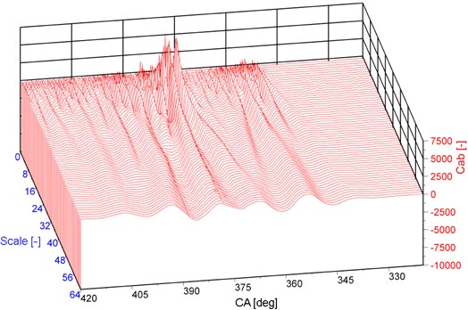
Figures present crank angle-scale representation for three different simulated clearance values. Trace obtained for nominal clearance are presented on Fig. 2, meanwhile Fig. 3 presents results for 2 times bigger clearance and figure 4 for the 4 times bigger clearance. Changes in signal traces due to bigger clearance may also be noticed in time frequency plane.
Accelartion signals registrated for three different clearances value have been analyzed with the use of CWT (Continues Wavelet Transform). First, searched the right level of scale which could separete components of mechanical phenomena from components of combustion process and enable to identify of simulated piston clearance value.
Fig. 2CWT for nominal clearance
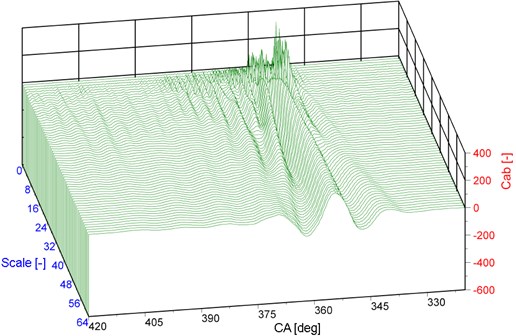
Fig. 3CWT for two Times bigger nominal clearance
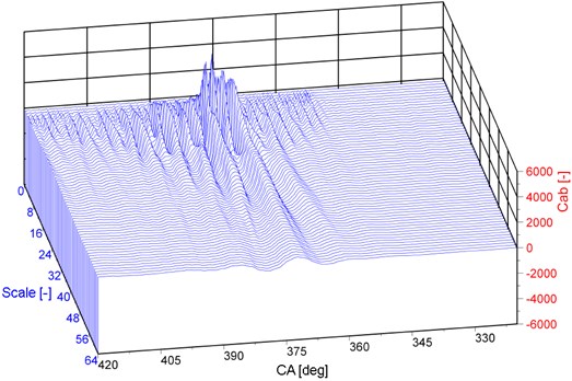
Fig. 4CWT for four times bigger nominal clearance
For signals after wavelet transformation were carried out calculation of wavelet coeficient derivative . Results shown on the Figs. 5 and 6.
Fig. 5Derivative of wavelet coefficient distribution
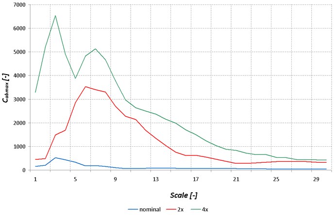
Fig. 6Derivative of wavelet coefficient for piston skirt clearance
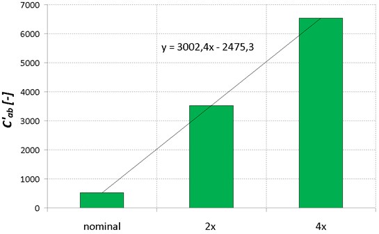
Derivative of wavelet coefficient distributions are shown that the maximal value of ferquency for different piston skirt clearance value tend to move in the direction of higher frequency values. It also shown that the vibration signals have higher value together with increase of piston skirt clearance.
4. Conclusions
The wavelet transform is powerful tool for on-line monitoring and diagnostic of combustion process and engine systems estimation. It can recover important features of the vibration signal that are sensitive to the change of IC engine condition. That is the reason to apply the CWT transform.
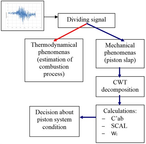
Based on the results authors have proposed detection and piston skirt clearance monitoring algorithm. Scheme of that agorithm is shown on the Fig. 7.
Fig. 7Engine piston system condition algorithm
References
-
Shibata K., Takahashi A., Shirai T. Fault diagnosis of rotating machinery through visualization sound signals. Mechanical Systems and Signal Processing, Vol. 14, 2000, p. 229-241.
-
Wang W. Q. Ismail F. Golnarghi F. Assessment of gear damage monitoring techniques using vibration measurements. Mechanical Systems and Signal Processing, Vol. 15, Issue 5, 2003, p. 905-1022.
-
Bai M. R., Jeng J., Chen C. Adaptative order tracking technique using recursive last-square algorithm. Journal of Sound and Vibration, Vol. 124, 2004, p. 502-511.
-
Tse P. W., Yang W. X., Tan H. Y. Machine fault diagnosis trough an effective exact wavelet analysis. Journal of Sound and Vibration, Vol. 227, 2004, p. 1005-1024.
-
Lin J., Qu L. Feature extraction based on Morlet wavelet and its application for mechanical fault diagnosis. Journal of Sound and Vibration, Vol. 234, Issue 1, 2000, p. 135-148.
-
Jang S., Cho J. Effect of skirt profiles on the piston secondary movements by the lubrication behaviors. International Journal of Automotive Technology, Vol. 5, 2004, p. 23-31.
-
Antoni J., Daniere J., Guillet F. Effective vibration analysis of IC engines using cyclostationarity. Part I – A methodology for condition monitoring. Journal of Sound and Vibration, Vol. 257, Issue 5, 2002, p. 815-837.
-
Badaoui M. El., Daniére J., Guillet F., Serviére C. Separation of combustion noise and piston-slap in diesel engine – Part I: Separation of combustion noise and piston-slap in diesel engine by cyclic Wiener filtering. Mechanical Systems and Signal Processing, Vol. 19, 2005, p. 1209-1217.
-
Geng Z., Chen J. Investigation into piston-slap-induced vibration for engine condition simulation and monitoring. Journal of Sound and Vibration, Vol. 282, 2004, p. 731-751.
-
Inagaki M., Kawamoto T., Yamamoto K. Prediction of structural and kinematic coupled vibration on internal combustion engine. R&D Review of Toyota CRDL, Vol 37, No. 2.
-
Flekiewicz M., Madej H. Influence of Combustion Noise on Engine Block Vibration in IC Engine Fueled by LPG. VAFSEP 2006, p. 67-75.
-
Flekiewicz M., Flekiewicz B., Fabiś P., Madej H., Wojnar G. Influence of piston slap on engine block vibration. SAE Paper 2007-01-2163.
-
Folęga P., Siwiec G. Numerical analysis of selected materials for flexsplines. Archives of Metallurgy and Materials, Vol. 57, Issue 1, 2012, p. 185-191.
-
Burdzik R., Folęga P., Łazarz B., Stanik Z., Warczek J. Analysis of the impact of surface layer parameters on wear intensity of friction pairs. Archives of Metallurgy and Materials, Vol. 57, Issue 4, 2012, p. 987-993.
About this article

