Abstract
A separate Braille element is analyzed. Axisymmetric problem for the first harmonic in the circumferential direction is investigated. Maximum equivalent stresses on circles on the boundaries of the structure for the first eigenmodes are obtained. At the places of maximum equivalent stresses deterioration of quality of material of a polymeric film is expected. One dimensional model for the investigation of longitudinal vibrations of polymeric film is used for the determination of number of cycles till start of wear when the film performs vibrations according to the eigenmode. Graphical representations for different values of the parameter of the model are obtained. The results of performed investigations are used in the process of interpretation of measurements of wear of vibrating polymeric films used in the process of printing and production of material with Braille elements.
1. Introduction
A separate Braille element is analyzed. Axisymmetric problem for the first harmonic in the circumferential direction is investigated. Maximum equivalent stresses on circles on the boundaries of the structure for the first eigenmodes are obtained. At the places of maximum equivalent stresses deterioration of quality of material of a polymeric film is expected.
Clarity of Braille reading depends on type of the surface of material it is formed on [1]. This is because of the fact that surfaces of materials differ in their topography and are perceived differently in the senses of visually impaired human beings. The results show that the friction coefficients between the human finger and different types of surfaces explain the unique nature of these senses [2].
Mechanical behavior for wrinkling of elastic faces in structural sandwich panels was established long ago [3]. It has been revisited recently [4-6] for nonlinear analysis and inelastic behavior of thin films.
In the paper [7] studies of wrinkling of an elastic film on a viscoelastic substrate with a relaxation modulus which is typical for cross-linked polymers have been performed.
The ideas of the bulk mechanical and thermodynamic properties of the materials used in the structure as well as the detailed properties of various interfaces are illustrated in detail for a simple typical structure, which is subjected to thermal expansion and thus experiences mismatch of stresses. Detailed finite element calculations of the relevant stress distributions are presented in [8].
The numerical procedure is based on the formulation of the axisymmetric problem for the first harmonic in the circumferential direction [9, 10] and representation of equivalent stresses [11].
One dimensional model for the investigation of longitudinal vibrations of polymeric film is used for the determination of number of cycles till start of wear when the film performs vibrations according to the eigenmode. This model is based on the material presented in [9, 12-14]. The stress field for each eigenmode is calculated by using the procedure of conjugate approximation [13, 14]. Then the number of cycles till the start of wear for each eigenmode is calculated. This calculation is based on the material presented in [15]. Graphical representations for different values of the parameter of the model are obtained.
The presented results are used in the process of interpretation of measurements of wear of vibrating polymeric films which are used in the process of printing and production of material with Braille elements.
2. Investigation of stresses in a separate Braille element
2.1. Numerical procedure
Further denotes the radial coordinate, denotes the axial coordinate and denotes the coordinate in the angular direction, while denotes the angle of the system of coordinates. The following notation is introduced:
where , , … are the shape functions of the two dimensional finite element.
The displacements , and are expressed as:
where is the vector of nodal amplitudes of the first harmonic of displacements and:
The mass matrix has the form:
where is the density of material of the elastic structure.
The following notation is introduced:
The strains are expressed as:
where:
The stiffness matrix has the form:
where is the matrix of elastic constants.
Equivalent stress is determined as:
where , , , , , are the stresses.
For the investigated problem:
where:
where the superscripts and denote the cos and sin amplitudes of the stresses.
Thus the maximum equivalent stress on a circle is determined from:
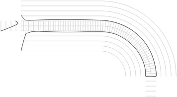
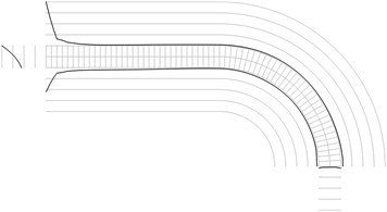
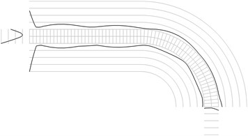
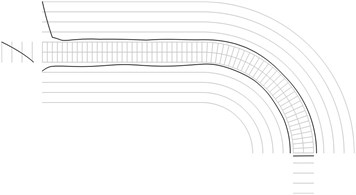
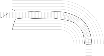
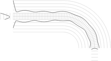
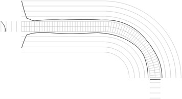
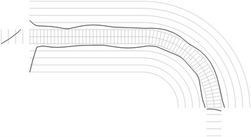
Fig. 1Maximum equivalent stresses on circles on the boundaries for a) the first, b) the second, …, j) the tenth eigenmodes
a)
b)

c)
d)
e)
f)
g)
h)
i)
j)
2.2. Investigation of the stress field
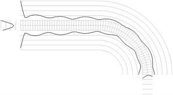
The structure consists of one row of elements located on a straight part with the length equal to the length of the middle line of one fourth of a circle and then of one fourth of a circle. The radius of the middle line of the part of the circle is 0.001 m and semi thickness of the structure is 0.0001 m The following parameters are assumed: modulus of elasticity 6×10⁸ Pa Poisson’s ratio 0.3, density of the material 785 kg/m3. The left end of the structure coincides with the axis of symmetry.
All amplitudes of displacements of the three nodes on both ends of the structure are assumed equal to zero. Maximum equivalent stresses on circles on the boundaries of the structure for the first eigenmodes are presented in Fig. 1. Equivalent stresses on the surfaces are represented graphically in the normal direction to the boundaries of the structure.
From experimental investigations it can be noticed that deterioration of quality of polymeric material usually starts from the surfaces of the investigated sample. This indicates that the results of equivalent stress on the surfaces of polymeric film are of special importance. At the places of maximum equivalent stress defects in the material usually start to develop after a number of cycles of loading.
3. Investigation of measurements of the number of cycles till the start of wear in a vibrating polymeric film
3.1. Model used for the analysis
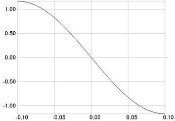
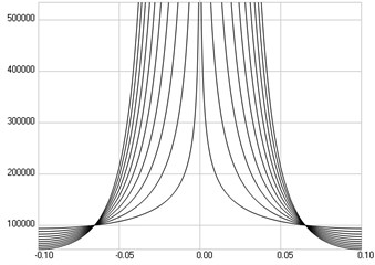
One dimensional finite element is in the direction of the axis of the system of coordinates. The finite element has one nodal degree of freedom, the displacement in the direction of the axis. Eigenmodes are calculated and then the distribution of the longitudinal stress in the polymeric film in the status of maximum displacement according to the eigenmode for each eigenmode is determined. Number of cycles till the start of wear is calculated as:
where and are parameters to be determined from experimental investigations.
3.2. Results of the analysis
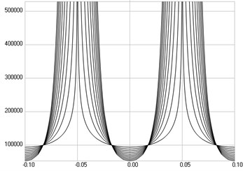
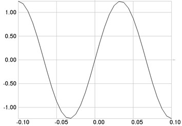
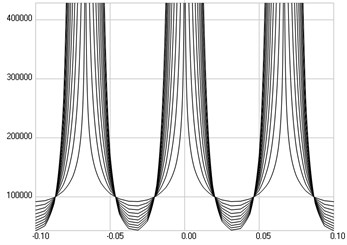
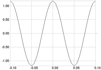
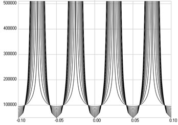
Length of the analyzed structure is 0.2 m. On the left and the right ends of the structure the displacements are equal to zero. The following parameters of the polymeric film are assumed: modulus of elasticity 6·108 Pa, Poisson’s ratio 0.3, thickness 0.0001 m, density of the material 785 kg/m3. It is assumed that the value of the parameter 105. The values of parameter are assumed from 0.4 up to 4. They are changed by equal increments and results for 10 values are represented.
The first eigenmode is investigated. Stresses are presented in Fig. 2(a), numbers of cycles till the start of wear in Fig. 2(b).
The second eigenmode is investigated. Stresses are presented in Fig. 3(a), numbers of cycles till the start of wear in Fig. 3(b).
The third eigenmode is investigated. Stresses are presented in Fig. 4(a), numbers of cycles till the start of wear in Fig. 4(b).
The fourth eigenmode is investigated. Stresses are presented in Fig. 5(a), numbers of cycles till the start of wear in Fig. 5(b).
From the presented model for determination of the number of cycles of loading till the start of wear it is clear that the presented drawings are applicable in experimental determination of the parameters of the model. This follows from the fact that the value of changes only the scale of the axis in the graphical relationships describing the numbers of cycles till the start of wear and the relationships for a number of typical values of the parameter are presented. Thus the obtained results are used in experimental procedures for measurement of both parameters and investigations of wear of polymeric films.
Fig. 2The first eigenmode: a) stresses, b) numbers of cycles till the start of wear
a)
b)
Fig. 3The second eigenmode: a) stresses, b) numbers of cycles till the start of wear
a)
b)
Fig. 4The third eigenmode: a) stresses, b) numbers of cycles till the start of wear
a)
b)
Fig. 5The fourth eigenmode: a) stresses, b) numbers of cycles till the start of wear
a)
b)
4. Experimental measurement of the number of cycles till the start of wear in a vibrating polymeric film
The main problem for the determination of the number of cycles till the start of wear in a vibrating polymeric film is the scatter of the obtained experimental results. Thus investigation of a number of samples and further statistical processing of the obtained results is required.
Special procedure of experimental investigations is proposed for this type of problems. The main steps of the procedure are indicated in the schematic diagram presented in Fig. 6. In this diagram investigation of the sample of the polymeric film takes place. It is assumed that samples 1, 2, …, 1 already have been analyzed and they have reached the state of failure of the material of polymeric film. Thus they are shown placed in the box of waste material. The samples 1, 2, …, are still waiting for their analysis and are located in the box of new polymeric films.
Fig. 6Schematic representation of the main steps of experimental procedure
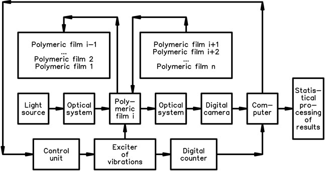
Fig. 7Typical data of experimental investigations
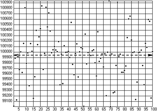
As a result of preliminary investigations it was determined that about 100 samples of polymeric film are required for successful statistical processing of results.
In the process of experimental investigations it was noticed that some of the samples of polymeric material result in substantially different numbers of cycles till the start of wear because of defects in the material of new polymeric films. They degrade the quality of results obtained from statistical procedures. Thus it is recommended to have about 120 samples before the start of experiment. From the performed investigations it was obtained that on the average about 10 samples give substantially different results and are classified as having defects. Their data are discarded and not used in further statistical analysis. So for further analysis the results of 100 samples of polymeric material which are considered to be without defects are used.
Typical experimental data are presented in Fig. 7. On the axis number of sample is indicated and on the axis number of cycles till the start of wear is shown. By applying the statistical operation of averaging the dashed line with arrows at both ends is obtained.
Satisfactory correspondence with numerical results obtained previously may be noted.
5. Conclusions
Axisymmetric problem for the first harmonic in the circumferential direction is investigated. Maximum equivalent stresses on circles on the boundaries of the structure for the first eigenmodes are obtained. From the presented results the places with maximum stresses are determined. From experimental investigations it is noticed that deterioration of quality of polymeric material usually starts from the surfaces of the investigated sample. This indicates that the results of equivalent stress on the surfaces of polymeric film are of special importance. At the places of maximum equivalent stress defects in the material usually start to develop after a number of cycles of loading.
One dimensional model for the investigation of longitudinal vibrations of polymeric film is used. The number of cycles till the start of wear for each eigenmode is calculated. Graphical representations for different values of the parameter of the model are obtained. The presented material is used for experimental determination of the parameters of the model determining the number of cycles till the start of wear of a polymeric film.
The obtained results are used in the process of interpretation of measurements of wear of vibrating polymeric films which are used in the process of printing and production of material with Braille elements.
References
-
Kouki D., Hiroshi F., Tsutomu W. Influence of base material of TRUCT Braille on readability of TRUCT Braille. WC 2009, IFMBE Proceedings, 2009, p. 235-238.
-
Kim M. S., Young Kim I., Kyu Park Y., Ze Lee Y. The friction measurement between finger skin and material surfaces. Wear, Vol. 301, 2013, p. 338-342.
-
Allen H. G. Analysis and Design of Structural Sandwich Panels. Pergamon Press, Oxford, London, Edinburgh, New York, Toronto, Sydney, Paris, Braunschweig, 1969.
-
Groenewold J. Wrinkling of plates coupled with soft elastic media. Physica A, Vol. 298, 2001, p. 32-45.
-
Huang Z. Y., Hong W., Suo Z., Mech J. Nonlinear analyses of wrinkles in films on soft elastic substrates. Physica Solids, Vol. 53, 2005, p. 2101-2118.
-
Huang R., Suo Z. Morphological instability of solid-on-liquid thin film structures. MRS Symposium Proceedings, Vol. 749, 2002, p. 121-126.
-
Huang R., Mech J. Kinetic wrinkling of an elastic film on a viscoelastic substrate. Physica Solids, Vol. 53, 2005, p. 63-89.
-
Lacombe Robert H. Stresses in Thin Polymeric Films: Relevance to Adhesion and Fracture. Part II of the book Surface and Colloid Science in Computer Technology, 1987, p. 179-198.
-
Huebner Kenneth H., et al. The Finite Element Method in Engineers. Wiley, New York, Chichester, 2001.
-
Weaver W., P. R. Structural Dynamics by Finite Elements. Prentice-Hall, New Jersey, 1987.
-
Kachanov L. M. Fundamentals of the Theory of Plasticity. Courier Corporation, Technology and Engineering, 2013, p. 496.
-
Bathe K. J. Finite Element Procedures in Engineering Analysis. Prentice-Hall, New Jersey, 1982.
-
Zienkiewicz Olek C., Taylor Robert L., Zhu J. Z. The Finite Element Method: Its Basis and Fundamentals. Butterworth-Heinemann, Technology and Engineering, 2013, p. 756.
-
Long Yu-Qiu, Cen Song, Long Zhi-Fei Advanced Finite Element Method in Structural Engineering. Springer Science and Business Media, Mathematics, 2009, p. 720.
-
Kovaliov N. A. Applied Mechanics. Vysshaja Shkola, Moscow, 1982, (in Russian).
About this article

L. Gegeckienė performed review of contemporary literature in the field of analysis of stresses of polymeric films and investigations of their wear and took part in the development of the numerical model used for the investigation of stresses in a separate Braille element. E. Kibirkštis developed the numerical model used for the investigation of stresses in a separate Braille element and performed the interpretation of the obtained stress fields on the surfaces of the Braille element. I. Venytė took part in the development of the numerical models used for the investigation of stresses in a separate Braille element and in the investigation of measurements of the number of cycles till the start of wear in a vibrating polymeric film. A. Voloshin proposed the method of experimental investigations of the number of cycles till the start of wear in a vibrating polymeric film and performed the comparison of experimental and numerical results of analysis. K. Ragulskis proposed the geometry of the investigated Braille element, the numerical models used for the investigations of both problems and performed the interpretation of the obtained numerical results of calculations. L. Ragulskis performed the computer implementation of graphical output of results of numerical calculations.
