Abstract
Face gear dynamics is one of study focuses of face gear drives, and addressed by many scholars. However, an engagement impact force calculation solution of face gear drives is not to be constructed, and some design suggestions for face gear drives considered engagement impact effects are also not to be extracted. Thus, in this study, an engagement impact force calculation solution of face gear drives is constructed, and a conversion solution between engagement impact energy and static transmission errors is proposed. Furthermore, based on a four DOF dynamic model formulated, the dynamic behavior difference of face gear drives between without and with engagement impacts is simulated, and sensitivity predictions of geometric parameters on engagement impacts are discussed. According to the limited analytic results in the issue, some design suggestions for face gear drives associated with lower engagement impacts are obtained. These contributions should improve the design of face gear drives in the future.
1. Introduction
A face gear drive with an involute pinion, namely, a kind of intersection gear drives, is addressed by scholars due to its insensitive characteristics of manufacture and alignment errors versus spiral bevel gear drives. Face gear drives are suggested to be used in the first stage gear drives of helicopter main gear boxes according to study achievements of Litven et al. [1-3]. One of operating characteristics of the first stage gear drives in helicopter main gear boxes is high rotation speed. Thus, face gear dynamics is a part of researching focuses of face gear drives, and is discussed by many researchers in the past few years. Li and Huang et al. constructed a calculation solution of a base parameter, namely mesh stiffness, of face gear dynamics [4]. Hu and Tang et al. evaluated the impact of mesh stiffness on dynamic behaviors of face gear drives [5]. Jin and Zhu et al. formulated a non linear face gear dynamic model [6]. Yang and Wang et al. assessed bifurcation and vibration characteristics with parameter excitations of face gear drives [7, 8]. Li and Zhu et al. investigated dynamic responses of non orthogonal face gear drives, and the influence of sliding friction on dynamic behaviors of face gear drives [9, 10]. Zhang and Zhu et al. studied torsion natural frequencies of face gear split torque transmission systems [11]. Wang and Zhao et al. discussed load sharing behaviors of face gear split torque transmission systems [12]. However, according to the limited published issues, calculation solutions of engagement impact forces of face gear drives are not to be constructed, and sensitivities of geometric parameters on engagement impacts of face gear drives are not to be investigated. Thus, in this study, an engagement impact force calculation solution of face gear drives is constructed, and a conversion solution between engagement impact energy and static transmission errors, meaning, STE, without an engagement impact damping, is proposed. A four DOF dynamic model is established, and differences of dynamic mesh forces between without and with engagement impacts are simulated. Furthermore, sensitivity predictions of geometric parameters on engagement impacts of face gear drives are investigated. The analytic results indicate some geometric parameters, such as pressure angles, shaft angles and drive ratios, are taken as bigger values, the influences of engagement impacts on dynamic behaviors of face gear drives are more insensitive. These contributions would benefit to improve the design of face gear drives.
2. Analytic solutions of face gear dynamic behaviors with engagement impacts
2.1. Constructed calculation solutions of engagement impact forces
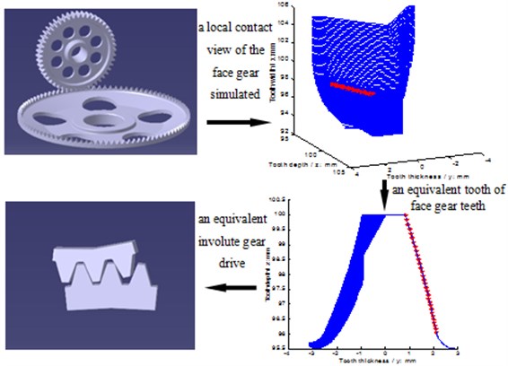
A face gear tooth can be considered as a sequence in which modified involute gears are superimposed along its face width, and point contact transmissions are employed in face gear drives due to offset load reasons. Thus, face gear drives can be equivalent as involute gear drives in contact viewpoints. The equivalent conversion between face gear drives and involute gear drives is given in Fig. 1.
Fig. 1Equivalent face gear drives
According to the reference [13], engagement impacts of involute gear drives are produced by the reason of outline mesh, as shown in Fig. 2, which is caused by tooth deformations, and manufacture and alignment errors.
As illustrated in Fig. 1 and Fig. 2, the caused reason of engagement impacts of face gear drives can be expressed as the outline mesh of equivalent face gear drives. According to the reference [13], engagement impact forces of face gear drives can be deduced as:
where is a input rotation speed of pinions, is a radius of pinion base circles, is a radius of pinion dedendum circles, is a drive ratio, is a pressure angle of pinion dedendum circles, is a pressure angle of pitch circles, is a pressure angle of reference circles, is a comprehensive errors of mesh lines, is a tooth width of equivalent face gears, and can be derived by:
where is a load, and are Poisson ratios, and are module of elasticity, and are contact radii, and are elliptic integral factors. is an induced mass of equivalent face gear drives, and can be written in [15]:
where subscript 1 and 2 are expressed as pinions and face gears, respectively, and can be given in [15]:
where is a rotational inertia, is an actual tooth width. Symbol is a flexibility at impact points of face gear drives. The detail derivations of and can be obtained in the reference [14] and [16], respectively.
2.2. Proposed conversion solutions between engagement impact energy and STE
According to the reference [13], engagement impact times are 5 %-10 % of engagement times, typically. Thus, without instantaneous engagement impact energy loss caused by engagement impact damping, which can not be predicted, instantaneous engagement impact energy of face gear drives can be deduced as:
where is a engagement impact time, and can be extracted as:
According to the law of conservation of energy, the instantaneous engagement impact energy is equal to the instantaneous tooth deformation energy, which can be expressed as:
where is an extra increase of STE caused by instantaneous engagement impacts, and can be expressed as:
Thus, the STE of face gear drives associated with engagement impacts can be obtained as:
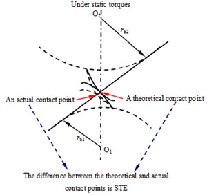
where is a traditional STE, as shown in Fig. 3, and can be deduced as:
where and , which can be calculated by the reference [15], are a face gear tooth deformation and a pinion tooth deformation respectively, and is a mesh error caused by manufacture and alignment errors.
Fig. 2Sketch of outline mesh of involute gear drives
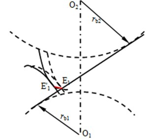
Fig. 3A definition diagram of traditional STE
2.3. Four DOF dynamic model
In order to evaluate the influence of engagement impacts on dynamic behaviors, and discuss sensitivities of geometric parameters on engagement impacts of face gear drives, a four DOF dynamic model, namely, bending and torsion coupled dynamic model, of face gear drives is established, as given in Fig. 4.
Fig. 4A four-DOF dynamic model of face gear drives
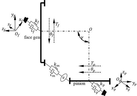
As shown in Fig. 4, mathematic equations of the dynamic model can be derived by:
where can be expressed as:
where is a torsion degree of freedom, is a bending degree of freedom, is a torsion, is a bending stiffness, is a bending damping, is a quality, is a moment of inertia, is first derivative, is second derivative, subscript and express a face gear and a pinion respectively. In addition, is mesh stiffness, is mesh damping, and is a STE.
3. Simulations and analyses
3.1. Simulation and sensitivity definition
In order to evaluate the influence of engagement impacts on dynamic behaviors of face gear drives, and define the sensitivity of engagement impacts on dynamic behaviors, geometric parameters, operating conditions and material characteristics of an example case of face gear drives are given in Table 1.
Table 1Parameters of an example case
Names | Values | Units | |
Geometric parameters | Modulus | 3 | mm |
Pressure angle | 25 | ° | |
Tooth number of pinions | 21 | – | |
Tooth number of face gears | 103 | – | |
Shaft angle | 90 | ° | |
Addendum coefficient | 1 | – | |
Clearance coefficient | 0.25 | – | |
Operating conditions | Power | 200 | kW |
Input rotation speed | 20900 | r/min | |
Material characteristics | Modulus of elasticity | 210000 | MPa |
Poisson ratio | 0.3 | – |
According to STE definitions, as shown in Fig. 3, and Eq. (10), the STE without engagement impacts of the example case, which parameters are listed in Table 1, is simulated in Fig. 5(a). Meanwhile, based on the proposed engagement impact force calculation solution, namely Eq. (1), and the constructed conversion solution between engagement impact energy and STE, meaning Eq. (8), the extra increase of STE of the example case is calculated. Then, the calculation result is introduced into Eq. (9) to achieve the simulation of STE with engagement impacts of the example case, as shown in Fig. 5(b).
Fig. 5STE of the example case
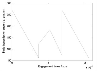
a) Without any impacts
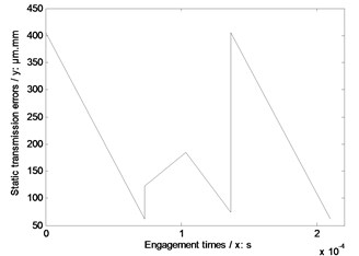
b) With engagement impacts
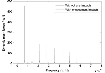
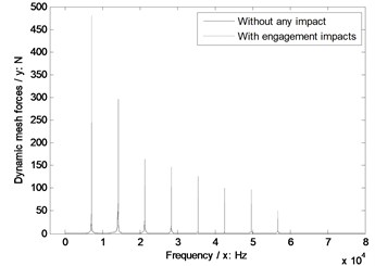
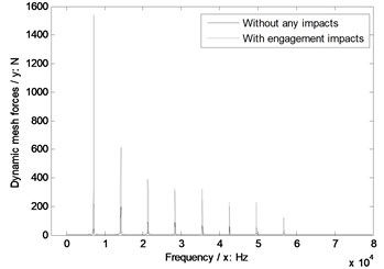
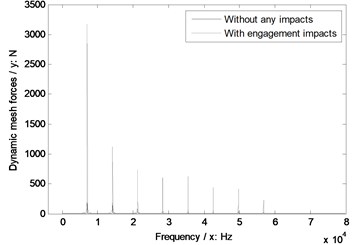
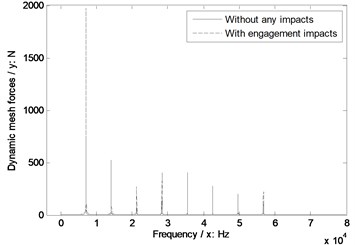
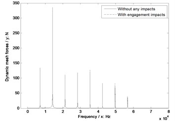
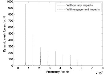
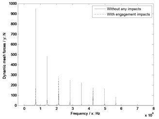
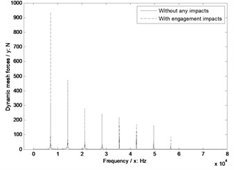
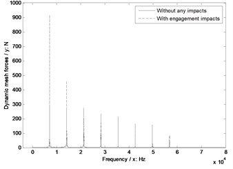
As illustrated in Fig. 5, the STE difference between without and with engagement impacts is the STE increase at starting engagement points. STE simulation results can be introduced into dynamic models directly, and effects of engagement impacts on dynamic behaviors can be reflected by STE differences between without and with engagement impacts. Thus, the dynamic mesh forces without and with engagement impacts of the example case are simulated, as shown in Fig. 6, by introducing the results of Fig. 5 into Eq. (11).
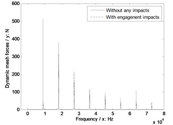
In the case of Fig. 6, the dynamic mesh force with engagement impacts is greater than that without any impacts. Thus, the sensitivity of engagement impacts on dynamic behaviors can be defined as the dynamic mesh force amplitude differences between without and with engagement impacts versus frequencies, which can be expressed as a curve, and the sensitivity curve of the example case is simulated, as shown in Fig. 7.
Fig. 6Dynamic mesh forces of the example case
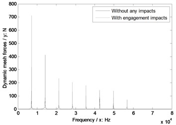
Fig. 7A sensitivity curve of the example case
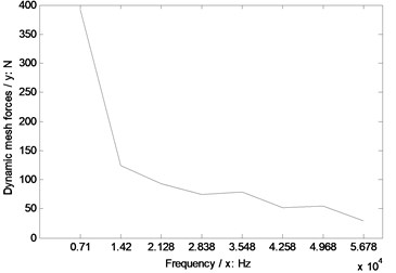
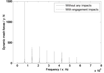
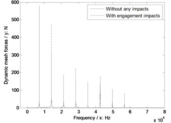
Fig. 8The sensitivity of module on engagement impacts
a) Modulus 3.5 mm
b) Modulus 4 mm
c) Modulus 4.5 mm
d) Modulus 5 mm
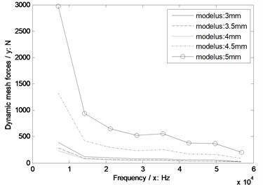
e) Sensitivity curves impacted by module
3.2. Analyses and sensitivity predictions
Based on the sensitivity defined, as given in Fig. 7, sensitivity predictions of geometric parameters on engagement impacts of face gear drives are investigated. In the analysis, the different geometric parameters of several example cases for sensitivity predictions are listed in Table 2.
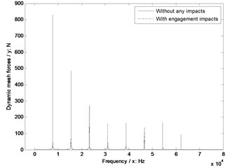
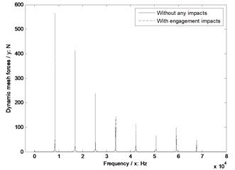
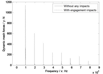
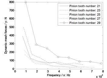
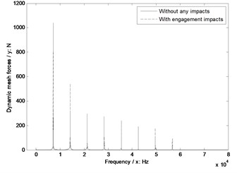
In simulations of sensitivity predictions, the base parameters are employed as listed in Table 1. The sensitivities of different geometric parameters, namely, module, pressure angles, pinion tooth numbers, face gear tooth numbers, and shaft angles, on engagement impacts of face gear drives are simulated and given in Fig. 8 to Fig. 12, respectively.
Fig. 9The sensitivity of pressure angles on engagement impacts
a) Pressure angle 20°
b) Pressure angle 22.5°
c) Pressure angle 27°
d) Pressure angle 29°
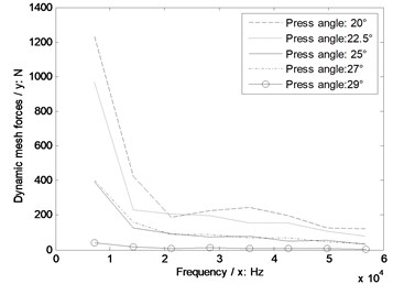
e) Sensitivity curves impacted by pressure angles
As illustrated in Fig. 8, without engagement impact effects, the dynamic mesh forces would be reduced with the increase of module. However, if engagement impacts were considered, under a certain operating condition, an optimal modulus, which would make dynamic mesh forces least, must be existed in the range of modulus designs.
As shown in Fig. 9, whatever without or with engagement impact effects, the dynamic mesh forces would be reduced with the increase of pressure angles, and the bigger pressure angles are more insensitive to engagement impacts of face gear drives.
In the case of Fig. 10, without engagement impact effects, the dynamic mesh forces would be increased with the increase of pinion tooth numbers. However, if engagement impacts were considered, the pinion tooth number, which is in the range of 25 to 27, would be the best for engagement impact effects of face gear drives.
Table 2Different geometric parameters of several example cases
Names | Value 1 | Value 2 | Value 3 | Value 4 | Units | |
Geometric parameters | Modulus | 3.5 | 4 | 4.5 | 5 | mm |
Pressure angle | 20 | 22.5 | 27 | 29 | ° | |
Tooth number of pinions | 23 | 25 | 27 | 29 | – | |
Tooth number of face gears | 95 | 97 | 99 | 101 | – | |
Shaft angle | 85 | 80 | 75 | 70 | ° |
Fig. 10The sensitivity of pinion tooth numbers on engagement impacts
a) Pinion tooth number 23
b) Pinion tooth number 25
c) Pinion tooth number 27
d) Pinion tooth number 29
e) Sensitivity curves impacted by pinion tooth numbers
In Fig. 11, whatever without or with engagement impact effects, the dynamic mesh forces would be reduced with the increase of face gear tooth numbers, and the greater face gear tooth numbers are more insensitive to engagement impacts of face gear drives.
In Fig. 12, whatever without or with engagement impact effects, the dynamic mesh forces would be reduced with the decrease of shaft angles. However, as for the sensitivity, the shaft angle as equal to 90° is the best, and the influences of the other values of shaft angles are almost same.
Fig. 11The sensitivity of face gear tooth numbers on engagement impacts
a) Face gear tooth number 95
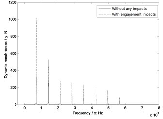
b) Face gear tooth number 97
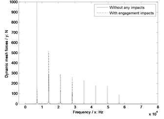
c) Face gear tooth number 99
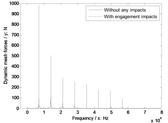
d) Face gear tooth number 101
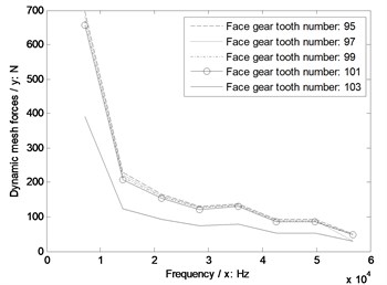
e) Sensitivity curves impacted by face gear tooth numbers
4. Conclusions
In the study, an engagement impact force calculation solution of face gear drives is constructed, and a conversion solution between engagement impact energy and STE is proposed. Furthermore, the sensitivity of engagement impacts on dynamic behaviors of face gear drives is defined, and sensitivity predictions of geometric parameters on engagement impacts are discussed. According to the limited analytic results in this issue, some design suggestions for face gear drives associated with lower engagement impacts can be extracted as follows:
1) Modulus should be chosen not only by strengths, but should consider engagement impacts in synchrony;
2) Pressure angles should be as bigger as possible;
3) Pinion tooth numbers should be taken in the range of 25 to 27;
4) Face gear tooth numbers should be as greater as possible;
5) Shaft angles should be designed as 90° as possible.
These suggestions would be helpful to reduce engagement impacts of face gear drives in design viewpoints.
Fig. 12The sensitivity of shaft angles on engagement impacts
a) Shaft angle 85°
b) Shaft angle 80°
c) Shaft angle 75°
d) Shaft angle 70°
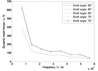
e) Sensitivity curves impacted by shaft angles
References
-
Litvin F., Bossler R., Chen Y.-J., Zhang Y., Wang J.-C. Design and geometry of face-gear drives. Journal of Mechanical Design, Vol. 114, Issue 4, 1992, p. 642-647.
-
Litvin F., Bossler R., Chen Y.-J., Lewicki D., Heath G., Wang J.-C. Application of face-gear drives in helicopter transmissions. Journal of Mechanical Design, Vol. 116, Issue 3, 1994, p. 672-676.
-
Litvin F. L., Egelja A., Tan J., Chen D., Heath G. Handbook on Face Gear Drives with a Spur Involute Pinion. DTIC Document, 2000.
-
Zhengminqing L., Peng H., Xiaozhen L. A calculation method of the stiffness of face gear tooth and analysis of its influence factors. Journal of Chongqing University, Vol. 37, Issue 1, 2014, p. 26-30, (in Chinese).
-
Hu Z. H., Tang J. Y., Chen S. Y., Lei D. C. Effect of mesh stiffness on the dynamic response of face gear transmission system. Journal of Mechanical Design, Vol. 135, Issue 7, 2013, p. 071005.
-
Jin G., Zhu R., Bao H. Nonlinear dynamical characteristics of face gear transmission system. Journal of Central South University (Science and Technology), Vol. 5, Issue 41, 2010, p. 1807-1813, (in Chinese).
-
Yang Z., Wang S.-M., Fan Y.-S., Liu H.-X. Bifurcation characteristics of face-gear transmission system. Journal of Harbin Institute of Technology, Vol. 3, Issue 43, 2011, p. 107-110, (in Chinese).
-
Yang Z., Wang S.-M., Fan Y.-S., Liu H.-X. Vibration characteristics of face-gear transmission system with parametric excitation. Journal of Chongqing University, Vol. 35, Issue 1, 2011, p. 26-35, (in Chinese).
-
Xiaozhen L., Rupeng Z., Zhengminqing L., Guanghu J. Analysis of coupled vibration of face gear drive with non-orthogonal intersection. Journal of Central South University (Science and Technology), Vol. 44, Issue 6, 2013, p. 2274-2279, (in Chinese).
-
Xiaozhen L., Rupeng Z., Zhengminqing L., Guanghu J. Influence of frictional coefficient on vibration characteristic of face gear transmission system. Journal of Vibration Engineering, Vol. 27, Issue 4, 2014, p. 584-588, (in Chinese).
-
Zhang L., Ru-Peng Z., Min-Qing L. Z. Research on natural frequency of torsional vibration of torque-split face gear transmission system. Jiangsu Machine Building and Automation, Vol. 41, Issue 5, 2012, p. 21-24, (in Chinese).
-
Wang R., Zhao N., Tao L., Jia Q., Guo H. Floating shaft load sharing method for face gear split torque transmission system. Research Journal of Applied Sciences, Engineering and Technology, Vol. 5, Issue 12, 2013, p. 3386-3392.
-
Wu Bao-Lin, Yang Su-Jun, Yao Jun-Hong Theoretical analysis on meshing impact of involute gears. Mechanical Science and Technology, Vol. 22, Issue 1, 2003, p. 55-57, (in Chinese).
-
Zhengminqing Li, Hao Wu, Rupeng Zhu Influence predictions of geometric parameters on face gear strength. Advanced in Mechanical Engineering, Vol. 7, Issue 3, 2015, p. 1-7.
-
Zhu X., E Z. Analysis of Load Capacity of Gears. Higher Education Press, Beijing, 1992, (in Chinese).
-
Zhengminqing Li, Hongshang Chen, Jiansong Chen, Rupeng Zhu Analytical impact of the sliding friction on mesh stiffness of spur gear drives based on Ishikawa model. Vibroengineering Procedia, Vol. 4, 2014, p. 29-33.
About this article

The authors are grateful for the financial support provided by the National Natural Science Foundation of China under No. 51105194 and No. 51375226, and the Fundamental Research Funds for the Central Universities under No. NS2015049. In addition, the authors declare that there is no conflict of interests regarding the publication of this article.
