Abstract
In this paper, we focus on the measuring rod of the gun barrel bore detecting system. The topology optimization model of the measuring rod is set up based on the variable density continuum structural topology optimization method. In order to minimize the static flexibility and to maximize the low vibration frequency simultaneously, the compromise programming approach is employed to optimize multi-objective topology. Optimization results show that an ideal distribution of material is acquired, which enhances the natural frequency of structure and reduces the structure quality, thus a synchronized multi-objective optimization is achieved. We validate the ultimate optimized topology with statics and dynamics analysis. The results show that both global stiffness and low frequency of the optimized measuring rod have been improved significantly which verify the rationality of the design.
1. Introduction
The accurate and effective test on the ablation condition of gun barrel bore is the basis for quality assessment of the gun barrel. In the detecting process, a measuring rod drives the measuring head into the gun barrel and then keeps the precise reciprocating motion of it. The precision of the measuring rod will directly restricts the accuracy of the detection. It is of great significance to optimize the structure of the measuring rod to improve the accuracy and absorb shock for the gun barrel bore detecting system.
In the process of traditional design, analogy method is often used for such parts. Although the strength is enhanced, the parts tend to be heavy and the material is also wasted. A low first order natural frequency may be generated due to the unreasonable design which will lead a larger vibration amplitude of the measuring rod at work. The traditional single-objective optimization approach can only solve some of the issues, and the requirements of deflection and vibration cannot be meet simultaneously. In our work, we set up a topology optimization model of the measuring rod and use the compromise programming approach for multi-objective topology optimization. A new measuring rod topology which minimizes the static flexibility and maximizes the low vibration frequency is built. The static and dynamic performance of the system and modal characteristics are examined to verify the rationality of the design.
2. Topology optimization model
2.1. Model of the measuring rod
The basic structure of the gun barrel bore detecting system is shown in Fig. 1 and the working principle is as follows. First, the stepper motor drives the driving shaft to rotate the gear which will actuate the rack. Then the rack pushes the measuring rod into the designated position of gun barrel to be measured. When the measurement is completed, the motor will start again to promote the measuring rod to the next position until the detection is finished. The ultimate data will be transferred to the computer synchronously. The acquisition, transmission, observation and storage courses for the data are all achieved.
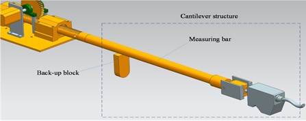
Regarding that the ratio of length to diameter of the gun barrel is out of range and the inner diameter is too small, the measuring rod of the gun barrel bore detecting system is usually designed with a cantilever beam to drive the measuring head into the barrel. The structure of the measuring rod is shown in Fig. 2. As the hanging part of the measuring rod is becoming increasingly long during the process of working, the deflection of the measuring rod is growing constantly with vibration. As a result, the measuring error is inevitable.
Fig. 1Gun barrel bore detecting system
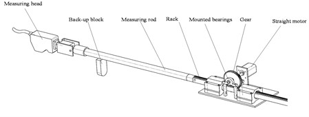
Fig. 2Structure of measuring rod
2.2. Topology optimization mathematical model
Continuum topology optimization searches for the optimal distribution of material and the best power relay route with a given constraint function. Homogenization method, variable density approach, thickness-varying method and progressive optimization level set method are the typical topology optimization methods. And homogenization method and variable density approach are most commonly used. Our topology optimization for measuring rod is based on the variable density approach provided by Optistruct Software.
A hypothetical material whose relative density ranges from 0 to 1 is introduced in the variable density approach. It is assumed that the relationship between the macro elastic modulus and the density of the design material is nonlinear. The material density is regarded as the design variables in the process of topology optimization. In this way, the structural topology optimization is converted into the optimal distribution problem of the material.
The equivalent elastic modulus of materials which is based on the variable density method can be expressed as:
where is the elastic modulus of materials after interpolation, represents the difference of elastic modulus between solid and hollow materials, denotes the relative density of the unit and is the penalty factor. In order to improve the stability of the numerical solution, we usually let . When is much smaller than , can be ignored, on this occasion, the above formula can be simplified as:
The stiffness matrix and flexibility matrix of the model are as follows:
2.3. Dynamic vibration frequency model
The dynamic vibration frequency of topology optimization aims to maximize some critical derivatives of the low order frequency by using the structural volume as a constraint function. The frequencies will be switched if the optimization goal is set to be a low specific frequency of the structure. The eigenvalues of the higher order frequency which are close to the optimization frequency are likely to be decreased and frequency switching may be occurred. The frequency switching phenomenon will influence the error sensitivity, and may do harm to the judgment of convergence of the model. In order to avoid this kind of phenomenon, the mean frequency formulation is used to define the objective function of inherent frequency topology optimization:
where is the mean frequency, represents the order characteristic frequency, and are the given parameters, is the weight coefficient of the order characteristic frequency and is the low frequency which needs to be optimized.
The mean frequency formulation defines a smooth objective function. As the low-order modals have been considered in the formula, the curve of this objective function remains smooth even if several low-order modals have been exchanged.
3. Multi-objective topology optimization methods
3.1. Compromise programming approach
The -constraint approach is a multi-objective topology optimization method which transforms multi-objective problems into single-objective ones. By using the method to optimize the objective functions, constraint functions are usually beyond the scope constraint conditions. Not all the Pareto optimal solutions can be acquired by using the linear weighted method to deal with the non-convex optimization problems.
The compromise programming approach aims to compromise each goals according to the design requirements to find an ideal solution. Different sub-goals are linked together through regularizing sub-objective function, and the weight of each target is set according to the importance of them.
The mathematical model of compromise programming approach is:
where and are variable functions, denotes the worst value of the sub-objective function, represents the optimal value of the sub-objective function and is the weight of each sub-target.
3.2. Multi-objective topology optimization
In the process of single-objective topology optimization, a decrease of compliance may cause a decline of the low frequency and when the low frequency are increased, the compliance are probably to be improved at the same time. Thus we must consider reducing the compliance and improving the inherent low frequency in the design phase to improve the performance of the measuring rod, and reduce the static deflection and dynamic vibration as well.
We consider the volume and deflection as constraints, and the stiffness and static frequency as the objective functions in the process of multi-objective topology optimization for the measuring rod. Combining the compromise programming approach and mean frequency formulation, the comprehensive objective function is defined as follows:
where represents the comprehensive objective function, denotes the weight of the objective function of the compliance. and are the optimal and worst value of the objective function of the compliance, respectively. Simultaneously, is the optimal value of the objective function of the frequency and is the worst.
4. Experiment
4.1. Establishment of finite element model
The 3D entity model of measuring rod is established on the basis of 2D drawings and the actual structure by using UG Software. Then, the model is imported to Hyperworks Software to establish finite element meshes. As noticed from Fig. 3, the 3D and finite element models of the measuring rod are presented, respectively. The measuring rod is made of aluminum alloy. The weight of the measuring rod is 2 kg and the length is 500 mm. The material parameters are shown in Table 1.
Fig. 3Model of measuring rod
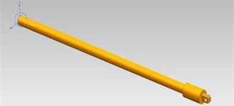
a) 3D model
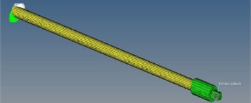
b) Finite element model
Table 1Material parameters
Material | Elasticity modulus / MPa | Poisson ratio | Density / cm3 |
Aluminium alloy | 71 | 0.33 | 2.81 |
4.2. Performance analysis of the measuring rod
The static performance of the model, such as the compliance and maximum static deflection are analyzed. Before this, we need to apply constraints on one side of the model, and apply a rated load of 20 N on the other. Of course, the original weight of the measuring rod should also be taken into account. The results of static characteristic analysis are shown in Table 2.
Then, the dynamic performance of the model is analyzed. The according inherent frequencies are shown in Table 3. As can be seen, the first order frequency of the measuring rod is 34.74 Hz. The environmental incentives are generally less than 20 Hz, and on this occasion the measuring rod is prone to resonate. Thus we need to increase its first order frequency.
Table 2Compliance and deflection
Compliance / (μm·N-1) | 6.24 |
Deflection / (mm) | 3.17 |
Table 3Modal frequencies of the measuring rod
Order | 1 | 2 | 3 | 4 | 5 |
Frequency (Hz) | 34.74 | 35.22 | 35.94 | 40.81 | 45.90 |
4.3. Optimization results
Regarding the actual design requirements of the measuring rod, the compliance weight and frequency weight are set to 0.4 and 0.6, respectively. Upon the above methods, the measuring rod is optimized and the material density distribution is acquired. As is shown in Fig. 4, the value of density varies from 0 to 1 progressively as the color of the model changes from blue to red. The material of the blue part can be reduced in the process of optimization. The middle part of the side which is under pressure can be emptied when improving the structural design of the original measuring rod combining with the optimization results.
The maximum static deflection and first order frequency are improved significantly after analyzing the static and dynamic performance of the new model. Fig. 5 describes the curve of the maximum static deflection before and after optimization. The maximum static deflection reaches 2.42 mm after optimization. Analogously, as can be seen in Fig. 6, the value of the first order frequency reaches 39.9 Hz after optimization.
Fig. 4Density distribution of the material
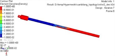
Fig. 5Maximum static deflection
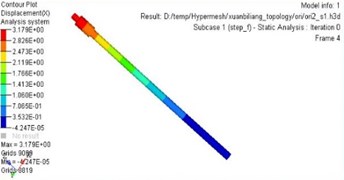
a) Before
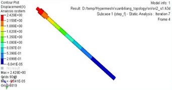
b) After
Fig. 6First order frequency
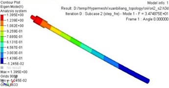
a) Before
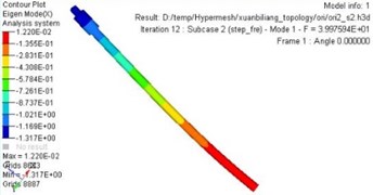
b) After
The performance before and after optimization are shown in Table 4. The weight of the measuring rod is reduced by 30 % after optimization, the compliance is decreased by 14.56 %, and the first order frequency is increased by 14.8 %. Both the dynamic and static performance of the measuring rod are improved significantly.
Table 4Comparative results before and after optimization
Optimizing content | Before | After | Optimization |
Compliance | 6.24 | 5.32 | 14.56 % |
Deflection / (mm) | 3.17 | 2.46 | 23.66 % |
First order frequency | 34.74 | 39.97 | 14.8 % |
5. Conclusions
In this paper, a mathematical model of multi-objective topology optimization is established based on the compromise programming approach, mean frequency formulation and SIMP density interpolation model. The multi-objective topology optimization is achieved which improves the overall performance of the measuring rod compared with the single-objective optimization. By taking into account the optimization objective from multiple perspectives, the performance indexes of the measuring rod such as stiffness, quality, deflection and low frequency have been improved effectively.
References
-
Suh J. D., Lee D. G. Composite machine tool structures for high speed milling machine. CIRP, Annals Manufacturing Technology, Vol. 51, Issue 1, 2002, p. 285-288.
-
Cheng Li Optimization on lower control arm of McPherson based on OptiStruct. Computer Aided Engineering, Vol. 21, Issue 5, 2012, p. 49-60, (in Chinese).
-
Min S., Nishiwaki S., Kikuchi N. Unified topology design of static and vibrating structures using multi-objective optimization. Computers and Structures, Vol. 75, Issue 1, 2000, p. 93-116.
-
Xiaoyuan Zhu, Zongde Fang, Shanshan Shen, et al. Muti-objective topology optimization for the control arm of vehicle suspension. Automotive Engineering, Vol. 33, Issue 2, 2011, p. 138-141, (in Chinese).
-
Yang X. Y., Xie Y. M., Liu J. S., Parks G. T., Clarkson P. J. Perimeter control in the bidirectional evolutionary optimization method. Structural and Multidisciplinary Optimization, Vol. 24, Issue 6, 2002, p. 430-440.
-
Zhou M., Shyy Y. K., Thomas H. L. Checkerboard and minimum member size control in topology optimization. Structural and Multidisciplinary Optimization, Vol. 21, Issue 2, 2001, p. 152-158.
-
Schmit L. A. Structural Optimization-Some Ideas and Insights. New Direction in Optimum Design. 1984.
-
Querin O. M., Young V., Steven G. P., et al. Computational efficiency and validation of bi-directional evolutionary structural optimization. Computer Methods in Applied Mechanics and Engineering, Vol. 189, Issue 2, 2000, p. 559-573.
-
Hassani B., Hinton E. Homogenization and Structural Topology Optimization: Theory, Practice and Software. Springer-Verlag, London, 1999.
-
Bendsoe M. P., Sigmund O. Topology Optimization Theory. Methods and Applications. Springer-Verlag, Berlin, Heidelberg, 2003.
-
Guan-Chun Luh, Chung-Huei Chueh Multi-modal topological optimization of structure using immune algorithm. Computer Methods in Applied Mechanics and Engineering, Vol. 193, Issues 36-38, 2004, p. 4035-4055.
-
Ma Z. D., Kikuchi N., Cheng H. C. Topological design for vibrating structures. Computer Methods in Applied Mechanics and Engineering, Vol. 121, Issues 1-4, 1995, p. 259-280.
-
Yu Yue-Qing, Howell Larry L., et al. Dynamic modeling of compliant mechanisms based on the pseudo-rigid-body model. Journal of Mechanical Design, Vol. 127, Issue 4, 2005, p. 760-765.
About this article

This is supported by the National Key Scientific Instrument Development Projects, No. 2013YQ470765.
