Abstract
To ensure excellent performance of a micro reflective space camera, an integrated main supporting structure (IMSS) combined with a thin-walled tube and a supporting rod structure design is applied in this study. Firstly, this paper covers the design and comparison of the performance of three traditional types of main supporting structures (MSS), including thin-walled cylinder type, rod-supporting type and truss type. Then, an IMSS combined with a thin-walled tube and a supporting rod structure is described. In addition, a multi-objective integrated optimization method which allows automatic modeling, analysis, calculation and optimization is proposed. Further, the influence of the supporting rod angle on the structure performance is studied, the performance of stiffness, deformation and mass is better when the height ratio of the rod-structure and the thin-walled cylinder is 6:1. The IMSS mass is only 0.56 kilograms, that is 11.2 % of the total mass of the payload, and the maximum deformation on the supporting bar is no more than 4.5 nm. Finally, the IMSS performance is analyzed by the finite element method and experimental verification, and the first order frequency is up to 192.7 Hz. The degree of light weight is significantly better than that of the traditional structures. The results of the experiment further prove the stability of the IMSS.
Highlights
- In order to meet the ultra-lightweight requirements of medium and small aperture space camera, an integrated main supporting structure design method combined with a thin-walled tube and a supporting rod structure is proposed in this study innovatively.
- Using the multi-objective optimization method, the weighted multi-objective topology optimization of IMSS is carried out to achieve the maximum structure stiffness of the camera within the finite mass.
- In order to avoid the redundancy of the structure size caused by indirect optimization mothed, in this article, the integrated optimization method is adopted to directly seek the relationship between the thickness size of IMSS and the first-order frequency, and mass of the camera.
1. Introduction
In the field of space remote sensing, microwave remote sensing information resources are very scarce. Especially, the high spatial and high temporal resolution satellite images are seriously inadequate [1, 2]. The improvement of resolution is accompanied by the enlargement of the reflector aperture and the lengthening of focal length, and then the volume and mass of the camera is increased. More attention has been paid to the microwave remote sensing payload with the advantages of small volume and high stability. The development of micro load technology brought new direction to the enhancement of data capacity for remote sensing payload.
To balance the contradiction between high stability and high-quality lightweight design, ultra-lightweight design of the camera structure is necessary. Great progress has been made in the development of ultra-lightweight mirror for space cameras [3]; however, the lightweight design of the MSS is not such a perfect performance, because it is achieved by the complex structure. What is more, the MSS occupies a large proportion in the overall mass of the camera. Meanwhile, MSS with the role of installing and positioning components ensures the position accuracy of each optical element that plays a decisive effect on the good imaging of the camera. The MSS of the coaxial reflective optical system mainly has three types: thin-walled cylinder type, rod-supporting type, and truss type. The thin-walled cylinder type structure is mainly used in the camera with high structural stability and looser weight control. For instance, the MSSs of space remote sensors on Quickbird-2 [4], GeoEye-1 cameras, KompSat-3 cameras [5], ALSAT-2A [6], and Formosat-2 cameras [7] are all designed in the cylinder type. However, the rod-structure is simple and mainly used for space cameras with high weight requirements. The third mirror supporting structure of the JMAPS optical telescope [8] developed by the US Naval Observatory, the MSS of the Mirror Satsang [9] is typical three-bar structures. The MSSs of ASTRI SST-2M telescope [10], James Webb Space Telescope [11] and SPICA Infrared Space Telescope [12] are the typical four-bar structure. Compared with the thin-walled cylinder type and rod-support type, the truss supporting structure has higher stiffness ratio and flexible assembly. It is widely used in large and medium-sized and multi-axis, coaxial and off-axis space cameras. For instance, these MSSs are used in the Hubble telescope [13], the EUCLID space telescope [14], and the high-resolution camera on the SPOT-7 satellite [15], the European Space Agency’s PROBA-V satellite [16], ALOS-3 satellite optical load [17] and a long focal space camera [18].
In recent years, more and more scientists make a lot of researches on the optimization method of the MSS. These researches are mainly based on two aspects. On the one hand, it aims at the lightweight and static stability of the MSS, for instance, Wang Tailei studied the relationship between the lightweight degree and the static mechanical index for the MSS of Micro-nano space camera [21]; Li Weiyan studied the relationship between the thermodynamic properties and optical parameters for the space camera MSS made of SiC/Al material [22], and so on. On the other hand, it aims at the lightweight and dynamic performance of the MSS. Such as, Wei Lei studied the relationship between the truss dimensional parameters and the random vibration response for a large off-axis TMA space camera [23]. However, the above two aspects of research are mainly aimed at the MSS with the determined configuration, which may not meet the ultra-lightweight requirements of the space camera. Therefore, it is necessary to study a new main support structure to ensure the excellent dynamic and static mechanical properties, ultra-lightweight quality requirements for the space camera. The ultra-light weight of opto-mechanical structures require that the mass of MSS should be minimized on the premise of satisfying the stability. This paper presents an IMSS with ultra-lightweight and high stability for a micro space camera with its aperture of 200 mm, while the distance between the primary mirror and the secondary mirror is more than 300 mm, and the mass of the whole camera should be less than 5 kilograms. In addition, a multi-objective integrated optimization method of set modeling, analysis, calculation, and optimization is described. The stability and lightweight design of IMSS is discussed in-depth.
2. MSS design
After comparison and selection of the common material properties of MSSs, a composite material (SiC/Al) with high stiffness, high thermal properties and small coefficient of linear expansion was accepted for design and fabrication of MSS for the micro payload. According to the structure design requirements of the ultra-light space camera and the characteristics of the optical system, three types of traditional MSSs are designed. These are of thin-walled cylinder type, rod-support type, and truss type. The optimal design of the three types is carried out with the first-order frequency (FOF) as the constraint and the minimum mass as the target.
2.1. Traditional MSS
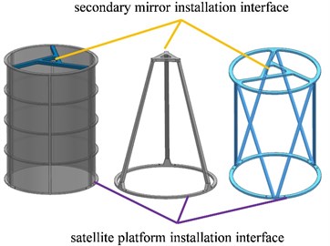
The initial 3D models of the traditional MSS are shown in Fig. 1. The satellite platform installation interface is fixed, and the mass of primary mirror and secondary mirror is connected with its own installation interface. According to the optimization method proposed in this paper, the structure is optimized. The optimization method will be described in Section 3 in detail.
Fig. 1Initial 3D models of traditional MSS
For thin-walled cylinder type, the thickness of the cylinder and ring bar, the width of longitudinal bar, and the thickness and width of the secondary mirror supporting rod are the optimized variables. After optimization, the cylinder thickness is merely 0.8 mm which is very difficult to machine and limited by the SiC/Al processing technology. The ring bar is 1mm while the longitudinal bar is 3.4 mm. The thickness and width of the secondary mirror supporting rod is 3 mm and 5 mm, respectively. The mass of thin-walled cylinder structure is 0.701 kilograms in this condition, and the FOF is 208.49 Hz. The maximum displacement of the secondary mirror (DSM) is 18 nm of the gravity field, and the temperature fluctuation is ±5 °C.
As for the rod-support type, the thickness and width of the secondary mirror supporting rod and the thickness of the MSS rod are variable. After optimization, the thickness and width of the secondary mirror supporting rod are 7.1 mm and 8 mm, respectively, the thickness of the MSS rod is 5.5 mm but its length is up to 330 mm. The mass of rod-support structure is 0.364 kilograms, and the FOF is 199.5 Hz. The maximum DSM is 15.7 nm in this rod-support type structure. This result is caused by the direct deformation of the MSS rod.
When it comes to the truss type, the thickness and length of the secondary mirror supporting rod and diameter of the MSS rod are variable. After optimization, the thickness and width of the secondary mirror supporting rod are 3.2 mm and 3.6 mm, respectively, the diameter of the MSS rod is only 5.6 mm but its length is up to 325 mm. The mass of the truss structure is 0.336 kilograms, and the FOF is 196.02 Hz. The DSM is 15.5 nm under the same condition. In this structure, there are more truss members and more connection interfaces with the upper and lower mounting boards that increases the difficulty of connection, and requires multiple embedded parts that will greatly increase the mass and makes the operability more difficult, and also accompanied with a high cost.
2.2. Performance of traditional MSS
The performance of MSS is the key source to ensure the stability of the whole camera structure. It is very important that the stiffness of MSS met the requirements. For this purpose, the engineering analysis of the optimized traditional MSSs was carried out. The properties of thin-walled cylinder type, rod-support type, and truss type are shown in Table 1.
Table 1Performance comparison of traditional MSSs
Item | Thin-walled cylinder type | Rod-support type | Truss type |
FOF (Hz) | 208.47 | 199.50 | 196.02 |
Mass (kg) | 0.701 | 0.364 | 0.366 |
-displacement (nm) | 5.83 | 0.006 | 4.82 |
/-displacement (nm) | 1.37 | 5.09 | 4.8 |
Thermal deformation (nm) | 18 | 15.7 | 15.5 |
When there were attempts to optimize three traditional MSSs, it occurred that it was difficult to ensure the FOF to meet the design requirements for three rod-support type, easier for the truss type, and for the thin-walled cylinder type. That is to say, the thin-walled cylinder type is the easiest to reach the stiffness requirement, the truss type is second, and the rod type structure is almost too difficult to realize. For the micro payload, the requirement of light weight is very strict. With the same stiffness, the thin-walled cylinder structure has the highest weight, and the rod structure is the lightest. The camera is affected by gravity load during its detection, installation, transportation, and while in orbit. The deformation of the optical elements is changed due to the excessive weight deformation which affects the imaging quality. Table 1 shows that both maximum displacement along optical axis and vertical displacement to optical axis reaches its maximum in the three rod-support type, followed by truss type, and thin-walled cylinder type and the stability of the rod type structure is poor. When the camera is in orbit, thermal environmental changes will cause thermal deformation, and this thermal deformation also affects the optical payload precision, therefore, the camera MSSs shall have high thermal stability. In the Table 1, the truss type structure has the worst thermal deformation, and the rod type structure has the best thermal stability.
Through an analysis and comparison, the thin-walled cylinder type is the best to reach the stiffness requirement, and the deformation under the gravity field is minimum. However, the mass is not suitable. The stiffness of the rod structure is lower, the deformation is the highest, its thermal stability is the best, and the mass is the lightest. The deformation of truss type structure is smaller than that of rod type structure, and its mass is lighter than that of cylinder type structure, but the thermal deformation is the largest. Structural stiffness and light weight are a pair of contradictions, and the key factor to the design of the MSS is to find its equilibrium point.
2.3. IMSS design
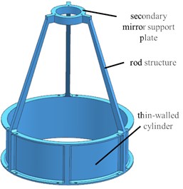
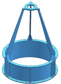
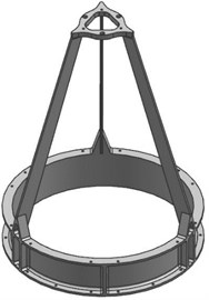
Through the study from Section 2.2, weight is reduced as much as possible to improve the structural stiffness, thus reducing the processing difficulty of the structure, a thin-walled cylinder type and rod-support type combined structure that is called IMSS is presented. The initial 3D model of IMSS is shown in Fig. 2. The IMSS is mainly composed of three parts: thin-walled cylinder, three rod structures, and the secondary mirror support plate. Hence, the IMSS is characterized by high stiffness properties of thin-walled cylinder type and high lightweight characteristics of the rod-support type structure. Three rod structures are evenly arranged with the angle of 120° so that the stress of the structure is uniformly distributed.
Fig. 2Initial 3D Models of IMSS
3. Optimization design
3.1. Structure topology
In this section, the topology optimization method is used to study the topology structure of a space camera main structure and mainly used to find the best topology form of the structure[19, 20]. Otherwise, the structure can achieve high efficiency and light weight, and improve the design efficiency. This lays the foundation for the integrated optimization.
The optimization model can be expressed as:
Optimization objective:
Constraints:
1) The IMSS shall weigh no more than 1 kilogram.
2) The DSM under gravity loads in the , and directions shall be no more than 0.01 mm, respectively.
In this model, is the optimization objective that is weighted by , and . Note that , and are the compliance functions of the whole structure under gravity in the , and directions, respectively. , and are weighting factors (this paper selects 0.33 for , and ).
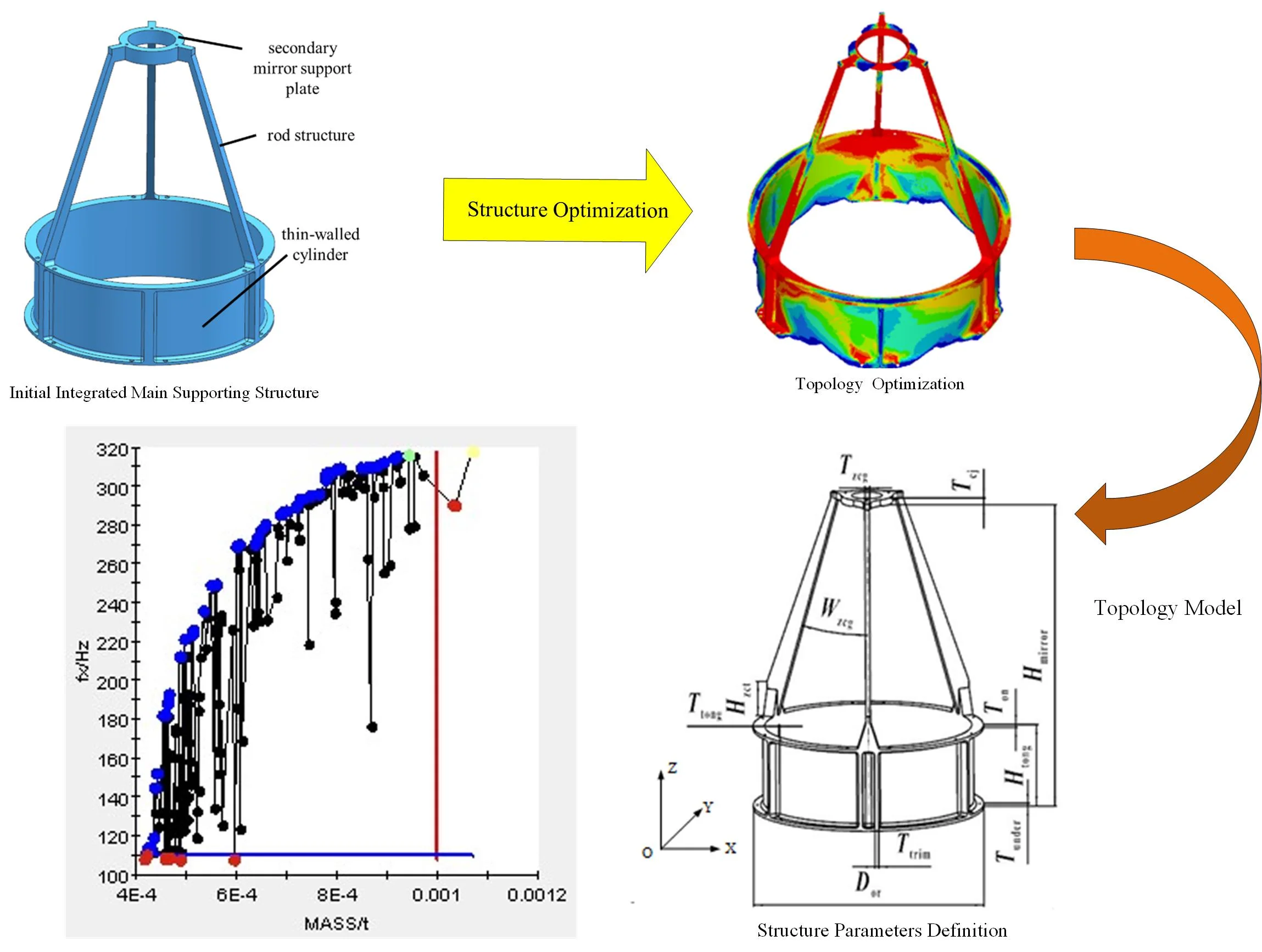
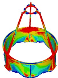
In accordance with the Initial 3D model of IMSS in Fig. 2, the FEM model of researched IMSS was established as shown in Fig. 3(a). After a large number of iterations of the optimization calculation, the authors obtained the optimal material distribution results for the optimization model under a gravity load in three directions (, , ). Since the topology optimization is based on the method of solid isotropic materials with penalization (SIMP), which takes the density of every FEM model element as the optimization variable, the final result given in Fig. 3(b) is shown in the form of a density cloud image. The red part indicates that the stiffness here needs to be strengthened. Based on the analysis of topology optimization results, combined with the engineering processing technology in engineering practice, the topology model of IMSS is shown in Fig. 3(c), and the mass is 0.794 kilograms.
Fig. 3Topology optimization of IMSS: a) FEM, b) topology optimization results, c) topology model
a)
b)
c)
3.2. Traditional MSS
Traditional experiential design methods and manual debugging methods are complex in operation and have low efficiency, so it is difficult to complete the global optimal results. The integrated optimization method-based software automatically modifies the parameterized model and seeks for the optimal result through its integrated operation, and it not only improves the design efficiency, but also optimizes multiple objectives simultaneously and seeks for the global optimal solution. In this section, Unigraphics NX and MSC, Patran & Nastran are integrated through ISight to optimize the structure. UG is used for parameterized modeling, automatic updating 3D model, Patran for pre-processing, and NASTRAN for solution and analysis. The size parameter optimization design of IMSS is carried out in Isight with the mass minimum and FOF maximum as optimization objectives.
3.2.1. Parameter definition
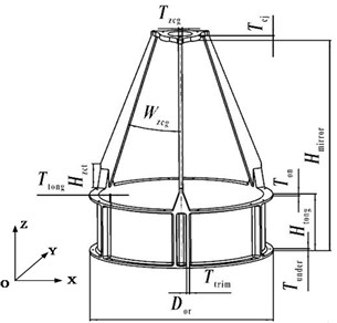
The parameters affecting the thermal performance of IMSS are shown in Fig. 4. The distance between the primary mirror and secondary mirror , and the outer envelope diameter of IMSS are not variable. While the others parameters, including the height and thickness of thin-walled cylinder, , and , such thickness of the flange which connected with the platform, , which thickness of the flange connected with the three rod-structures , thickness of the stiffeners on thin-walled cylinder , which height of the flange connected with the rod-structure and thin-walled cylinder , the angle between rod-structure and optical axis , thickness of the rod-structure and thickness of the secondary mirror support plate , are the design variables.
Fig. 4Structure parameters definition
3.2.2. Optimization of proportion between truss and thin-walled cylinder
The angle between the rod-structure and optical axis determines the proportion of the supporting rod-structure and thin-walled cylinder. It is the key parameter to find the equilibrium point between structural stiffness and light weight. Otherwise, it is meaningful to analyze the influence of the angle on the performance for the development of the ultra-light support structure. From the structural position relationship from Fig. 4, the range of the angle is expressed as Eq. (2):
Based on the solution of Eq. (2), the Eq. (3) can be gotten as follows:
Since, , are known, the conclusion can be gotten as follows:
Thanks to , the following conclusion can be made:
Setting up , the influence of the angle on the performance of IMSS can be studied by the ratio of height between the thin-walled cylinder and the distance between the primary mirror and secondary mirror (). Firstly, the influence of the angle on the FOF along the three orthogonal directions of the coordinate axis shall be studied. The results of the IMSS deformation in the change of primary and secondary mirror position, which directly affects the imaging quality of the camera. However, the primary mirror has little deformation and near the support plate, hence, the DSM is one of the decisive performances of the camera parameters. The influence of the angle changing the DSM under the gravity condition is also worth paying attention to. The influence of the angle on the main structure performance is shown in Fig. 5. Thanks to that the IMSS is circumferentially symmetric, the FOF in the and directions are the same. Therefore, the curve of FOF-Y and FOF-X overlaps in Fig. 5.
Fig. 5First order frequency
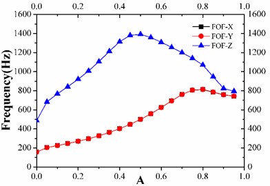
Fig. 6Mass of IMSS
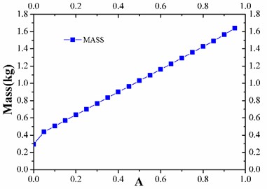
Fig. 7Displacement of secondary mirror
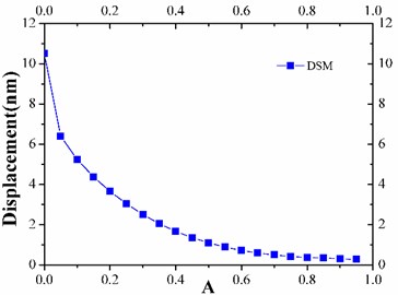
From Fig. 5, with the angle increase, the FOF along the three orthogonal directions rises first and then decreases. When the height of thin-walled cylinder, , is larger than 1/10 of the distance of primary and secondary mirror, , the FOF is above 200 Hz, which satisfies the design requirements. From Fig. 6, the DSM is inversely proportional to the angle, and the height of the thin-walled cylinder is smaller than 1/10 of the distance between primary mirror and secondary mirror, . The DSM exceeds 6 nm, and has serious influence on the stability of the system. According to Fig. 7, with the angle increase, the mass of IMSS increases linearly up to 1 kg beyond the design index of the main structure when the height of thin-walled cylinder is larger than 2/5 of the distance between primary and secondary mirrors. This means that the stiffness, deformation, and mass perform better when the height ratio of the rod-structure and the thin-walled cylinder is 6:1.
3.2.3. Progress of integrated optimization
The mass, deformation of secondary mirror and the FOF are the optimization objectives of main structure. The stiffness of structure is inversely proportional to DSM, ultimately, the mass and FOF are the optimization objectives, which belong to the multi-objective optimization. The mathematical description of the multi-objective optimization problem of IMSS is expressed as Eq. (6):
As described in Section 3.2.1, the parameterized modeling of IMSS is realized with Unigraphics NX8.0, and the finite element processing is completed with MSC Patran & Nastran. The integrated optimization process of parameterized modeling and analysis optimization is realized by Isight. The optimization process is shown in Fig. 8(a), and the solution process is shown in Fig. 6(b). The light weight and the high stiffness is a pair of contradictions. The optimization is multi-objective optimization problem. It is difficult to converge to the unique best-global optimal solution. Isight integration optimization obtains a set of feasible solutions which is called a Pareto optimal solution set. As shown in Fig. 8(b), each point in the graph is an optimization result, in which the blue dots are Pareto optimal.
Fig. 8Isight integrated optimization process
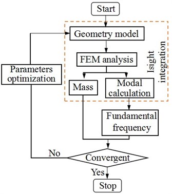
a) Optimization process
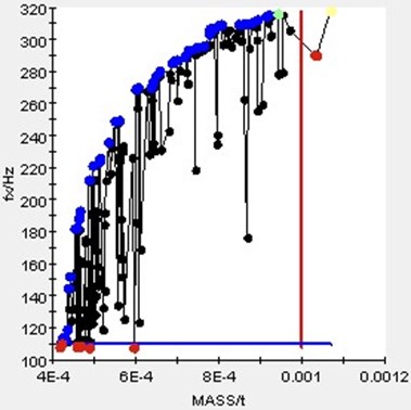
b) Solution process
The ideal solution for both the mass and the surface shape is selected from Pareto optimal solution set. The design variables, range of values, initial values, and final optimization results of the integrated optimization are shown in Table 2.
Table 2Design variables and optimization results
Variables | Range (mm) | Initial values (mm) | Optimization results (mm) |
[3.0, 15.0] | 5.0 | 6.95 | |
[2.0, 15.0] | 8.0 | 3.01 | |
[1.5, 6.0] | 4.0 | 1.72 | |
[1.5, 6.0] | 4.0 | 4.02 | |
[1.5, 6.0] | 4.0 | 2.98 | |
[1.5, 6.0] | 4.0 | 3.01 | |
[0.0, 50.0] | 5.0 | 30.0 |
After optimization, the thickness of the thin-walled cylinder is only 1.7 mm, and the thickness of the supporting rod-structure is only 3 mm, which is far less than the thickness of the traditional value. The mass of the optimized IMSS that the final 3D model of the IMSS shown in Fig. 9 is only 0.56 kilograms that is equal to 11.2 % of the total mass of the payload, and the maximum area of the deformation appears on the support bar with the sizes of no more than 4.5 nm to meet the design requirements well.
Fig. 93D model of IMSS after integrated optimization
3.3. Performance of IMSS
The degree of light weight of the IMSS is significantly improved than that of the traditional support structure. So it is necessary to investigate whether the support structure can ensure the position accuracy and surface accuracy of the mirror to meet the design requirements of various load conditions. The results of the engineering analysis of the primary mirror are shown in Table 3 and those for the secondary mirror are shown in Table 4.
Table 3Static performance of primary mirror
Primary mirror | RMS (nm) | -displacement (μm) | -displacement (μm) | -displacement (μm) |
Gravity | 1.16 | 0.84 | 0.01 | 0.05 |
±5 ℃ | 3.15 | 10.90 | 11.70 | 55.00 |
Gravity @ ±5 ℃ | 3.34 | 11.80 | 11.70 | 55.00 |
Table 4Static performance of secondary mirror
Secondary mirror | RMS (nm) | -displacement (μm) | -displacement (μm) | -displacement (μm) |
Gravity | 0.31 | 0.94 | 0.05 | 0.20 |
±5 ℃ | 2.63 | 0.16 | 0.31 | 64.00 |
Gravity @ ±5 ℃ | 2.64 | 11.00 | 0.30 | 66.00 |
Table 4 shows that the surface precision of the primary mirror under different working conditions is less than 3.5 nm, that is far better than the optical design requirements of /50, : 632 nm wavelength. The influence of gravity on the primary mirror deformation is also very small. From Table 5, it can be seen that the surface accuracy of the secondary mirror is less than 3 nm. It comes to our attention that the temperature fluctuation makes the DSM larger in -axis, but this size growth is within the design requirement range.
4. Experiments
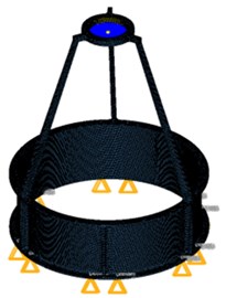
In addition to the statics performance, it is necessary to study the dynamic properties. Especially the response of random vibrations is a very effective method of verification. The vibration test conditions are shown in Table 5. Fig. 10 provides the FEM model of the whole space camera and shows the vibration test field.
Fig. 10FEM model of whole space camera and vibration test field
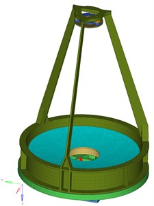
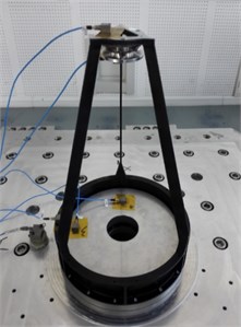
Table 5Random vibration conditions of mechanical prototype
Frequency (Hz) | value | RMS | Time |
10-80 | +3 dB/oct | 1.8 g RMS (35 %, 4.98 g RMS) | 2.0 min |
80-800 | 0.02 g2/Hz | ||
800-2000 | –6.0 dB/oct |
The response of random vibration in Table 6 shows that the relative error of the primary and secondary mirrors is not so high that it is acceptable, and the maximum error is 12.3 %. The other relative errors are within 10 %. Hence, the data in Table 6 further demonstrate the high stability of the structure on the other hand.
Table 6Results comparison of random vibration
Direction | Test (g) | Analysis (g) | Relative errors (%) | |
Primary mirror | 17.55 | 16.23 | 7.5 | |
20.23 | 19.38 | 4.2 | ||
13.22 | 13.91 | 4.9 | ||
Secondary mirror | 10.57 | 9.59 | 9.2 | |
10.13 | 11.56 | 12.3 | ||
5.92 | 6.39 | 7.3 | ||
5. Conclusions
Based on the study of the traditional supporting structure, this paper puts forward an IMSS combined with a thin-walled tube and a supporting rod, and has carried out the topology optimization and size optimization design. The optimization show that the performance of stiffness, deformation, and mass is better under the condition of the height ratio of the rod-structure and the thin-walled cylinder of 6:1. With this optimized result, the IMSS mass is 0.56 kilograms which is only 11.2 % of the total mass of the payload, and the maximum deformation appears on the support bar is no more than 4.5 nm which can meet use requirements.
Compared with the traditional structures, the degree of light weight of IMSS is significantly improved under the premise of ensuring the strength. The result of the vibration experiment further proves the feasibility and reliability of the structure.
References
-
S. I. Khan, Y. Hong, J. J. Gourley, M. U. K. Khattak, B. Yong, and H. J. Vergara, “Evaluation of three high-resolution satellite precipitation estimates: Potential for monsoon monitoring over Pakistan,” Advances in Space Research, Vol. 54, No. 4, pp. 670–684, Aug. 2014, https://doi.org/10.1016/j.asr.2014.04.017
-
L. Zhang, S. Ke, L. Li, and X. Jia, “Stiffness and deformation analysis of small elastic flexible hinge,” (in Chinese), Acta Photonica Sinica, Vol. 47, No. 1, p. 01220, 2018.
-
B. Dong and G. Zhang, “Fabrication and properties of ultra-lightweight SiC mirror,” (in Chinese), Optics and Precision Engineering, Vol. 23, No. 8, pp. 2185–2191, 2015.
-
T. Novack, T. Esch, H. Kux, and U. Stilla, “Machine learning comparison between WorldView-2 and QuickBird-2-simulated imagery regarding object-based urban land cover classification,” Remote Sensing, Vol. 3, No. 10, pp. 2263–2282, Oct. 2011, https://doi.org/10.3390/rs3102263
-
H.-O. Kim, H.-S. Kim, H.-S. Lim, and H.-J. Choi, “Space-based earth observation activities in South Korea [Space Agencies],” IEEE Geoscience and Remote Sensing Magazine, Vol. 3, No. 1, pp. 34–39, Mar. 2015, https://doi.org/10.1109/mgrs.2014.2382652
-
M. Kameche and S. Benmostefa, “In-flight MTF stability assessment of ALSAT-2A satellite,” Advances in Space Research, Vol. 58, No. 1, pp. 117–130, Jul. 2016, https://doi.org/10.1016/j.asr.2016.04.004
-
S. Lin, J. Chern, and A. Wu, “Optimization on mission operations of the handicapped FORMOSAT-2,” Acta Astronautica, pp. 243–249, 2014.
-
D. Catropa and F. Azad, “State-of-the-art silicon carbide optical telescope assembly for the JMAPS mission,” in SPIE Optical Engineering + Applications, p. 88370, Sep. 2013, https://doi.org/10.1117/12.2023118
-
C. Underwood, S. Pellegrino, V. J. Lappas, C. P. Bridges, and J. Baker, “Using CubeSat/micro-satellite technology to demonstrate the Autonomous Assembly of a Reconfigurable Space Telescope (AAReST),” Acta Astronautica, Vol. 114, pp. 112–122, Sep. 2015, https://doi.org/10.1016/j.actaastro.2015.04.008
-
R. Canestrari et al., “The ASTRI SST-2M prototype for the Cherenkov Telescope Array: manufacturing of the structure and the mirrors,” in SPIE Astronomical Telescopes + Instrumentation, p. 91450, Jul. 2014, https://doi.org/10.1117/12.2055805
-
J. A. Berrier et al., “Metrology for trending alignment of the James Webb Space Telescope before and after ambient environmental testing,” in Optical System Alignment, Tolerancing, and Verification XI, pp. 1–9, Aug. 2017, https://doi.org/10.1117/12.2273991
-
D. Castel, E. Sein, S. Lopez, T. Nakagawa, and M. Bougoin, “The 3.2m all SiC Telescope for SPICA,” in SPIE Astronomical Telescopes + Instrumentation, Vol. 8450, No. 4, p. 84502, Sep. 2012, https://doi.org/10.1117/12.926891
-
M. Livio, “Astronomy: Hubble’s legacy,” Nature, Vol. 520, No. 7547, pp. 287–289, Apr. 2015, https://doi.org/10.1038/520287a
-
J. Lavenac et al., “The SiC structure of the EUCLID NISP instrument,” in International Conference on Space Optics 2016, No. 18, p. 21, Sep. 2017, https://doi.org/10.1117/12.2296060
-
R. Dicati, Earth Remote Sensing: Stamping the Earth from Space. Springer International Publishing, 2017, pp. 293–359.
-
K. Mellab, S. Santandrea, and M. Francois, “PROBA-V: operational and technology demonstration mission – results after commissioning and one year of in-orbit exploitation,” in Small Satellites Systems and Services Symposium 2014, pp. 26–30, 2014.
-
H. Katayama, E. Kato, H. Imai, and M. Sagisaka, “Wide swath and high resolution optical imaging satellite of Japan,” in SPIE Asia-Pacific Remote Sensing, p. 98810, May 2016, https://doi.org/10.1117/12.2228061
-
L. Wei, L. Zhang, and P. Xie, “Optimization design and test for front frame of large off-axis TMA Space Camera,” (in Chinese), Acta Photonica Sinica, Vol. 46, No. 5, p. 52200, 2017.
-
H. A. Eschenauer and N. Olhoff, “Topology optimization of continuum structures: A review,” Applied Mechanics Reviews, Vol. 54, No. 4, pp. 331–390, Jul. 2001, https://doi.org/10.1115/1.1388075
-
M. P. Bendsoe, Topology Optimization: Theory, Methods and Applications, Second Edition. Springer, 2004.
-
T. L. Wang, L. Zhang, and X. Jia, “Optimization design of integrated ultra-light main supporting structure for micro-nano remote-sensing camera,” (in Chinese), Acta Optica Sinica, Vol. 39, No. 7, pp. 417–424, 2019.
-
W. Y. Lei, Q. Lü, and Y. Liu, “Thermal characteristics analysis and verification of primary supporting structure for Spcaeborne camera based on low volume SiC/Al primary mirror frame,” (in Chinese), Acta Photonica Sinica, Vol. 50, No. 4, pp. 215–225, 2021.
-
L. Wei, L. Zhang, X. Gong, and D.-M. Ma, “Design and optimization for main support structure of a large-area off-axis three-mirror space camera,” Applied Optics, Vol. 56, No. 4, p. 1094, Feb. 2017, https://doi.org/10.1364/ao.56.001094
Cited by
About this article

Guangdong Basic and Applied Basic Research Foundation (2020A1515110259).
