Abstract
The two dimensional system of coupled vibrating pipes is investigated. The model of a pipe system consisting from two dimensional beams is employed. The problem of stability because of the reduction of stiffness caused by the flow of fluid is solved and the stability eigenmodes are determined. The places where the deflections of the stability eigenmodes are large are recommended for the location of measurement devices.
1. Introduction
The two dimensional system of coupled vibrating pipes is investigated. The model of a pipe system consisting from two dimensional beams is used. The problem of stability because of the reduction of stiffness caused by the flow of fluid is solved and the stability eigenmodes are determined.
Measurement of vibrations of similar systems when the fluid does not flow was investigated in [1, 2]. In [1] vibrations in the plane of the two dimensional system of pipes were investigated and in [2] transverse vibrations of the two dimensional system of pipes were investigated. This paper continues the investigations presented in both previous papers.
The model for the analysis of stability of a pipe system is proposed on the basis of the results described in [1, 2] and general relationships presented in [3-5]. Similar problems of dynamics, vibrations and stability are investigated in [6-12].
2. In plane stability of a pipe system with flowing fluid
2.1. Model for the analysis of stability of a pipe system with flowing fluid
, and denote the axes of the system of coordinates. The finite element of a two dimensional beam representing the pipe in the plane has three nodal degrees of freedom: the displacement in the direction of the axis denoted as , the displacement in the direction of the axis denoted as and the rotation about the axis denoted as .
The displacements in the direction of the longitudinal axis of the pipe and in the direction of the axis perpendicular to and located in the plane are denoted as and and they are related with , as:
where is the local coordinate of the finite element of the pipe and
The following notation is used:
where are the shape functions of the one dimensional finite element of the pipe.
Also it is assumed:
The stiffness matrix of the pipe has the usual form:
where is the modulus of elasticity of the pipe, is the Poisson’s ratio of the pipe, is the internal radius of the pipe, is the external radius of the pipe and
The supplementary stiffness matrix of the model of a pipe because of the motion of the fluid in it has the form:
where is the density of the fluid filling the pipe and v is the velocity of the fluid inside the pipe.
The total stiffness of the pipe is equal to . If the velocity is changed times, then the stiffness becomes . This results in the eigenproblem for the determination of critical velocities and stability eigenmodes.
2.2. Analysis and measurement of stability of a pipe system with flowing fluid
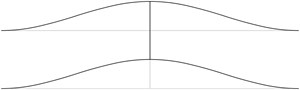
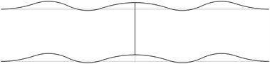
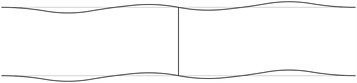
The structure consists from a lower straight pipe and an upper straight pipe both of them having fixed ends (all of the generalized displacements equal to zero) and they are assumed filled with water. The midpoints of both pipes are connected by an empty pipe perpendicular to them. Length of the structure is 2 m and the distance between the lower and upper pipes is 0.4 m.
The following parameters are assumed: modulus of elasticity of the pipes 6·108 Pa, Poisson’s ratio of the pipes 0.3, density of the fluid filling the two pipes 998 kg/m3, velocity of the fluid in the lower pipe is assumed to be equal to 1 m/s, velocity of the fluid in the upper pipe is assumed to be equal to –1 m/s, internal radius of the pipes 0.004 m, external radius of the pipes 0.006 m.
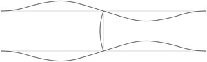
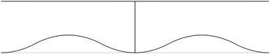
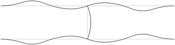
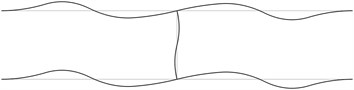
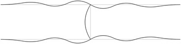
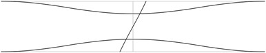
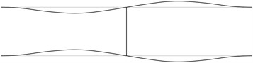
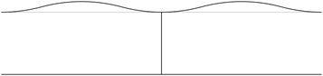
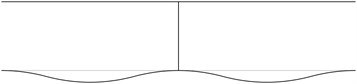
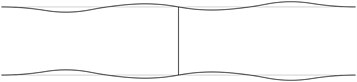
The first stability eigenmodes are presented in Fig. 1. The fourth and the fifth eigenmodes correspond to the same eigenvalue.
In order to perform precise measurements of stability of a pipe system the measurements of deflections of the pipes are to be performed not at the nodes of the stability eigenmodes and preferably at the places with maximum deflections. In practical applications usually the first eigenmode is important. Thus from the presented images of deflections the locations of measurement devices may be chosen.
Fig. 1The first stability eigenmodes of the pipe system: a) the first eigenmode, b) the second eigenmode, …, j) the tenth eigenmode
a)
b)
c)
d)
e)
f)
g)
h)
i)
j)
3. Transverse stability of a pipe system with flowing fluid
3.1. Model for the analysis of transverse stability of a pipe system with flowing fluid
The finite element of a two dimensional beam representing the pipe in the plane has three nodal degrees of freedom: the displacement in the direction of the axis denoted as , the rotation about the axis denoted as and the rotation about the axis denoted as .
The rotations about the longitudinal axis of the pipe and about the axis perpendicular to and located in the plane are denoted as and and they are related with , as:
where
The stiffness matrix of the pipe for the analysis of transverse stability has the usual form:
where
The supplementary stiffness matrix of the model of a pipe for the analysis of transverse stability because of the motion of the fluid in it has the form:
3.2. Analysis and measurement of transverse stability of a pipe system with flowing fluid
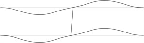
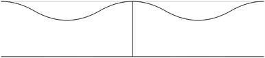
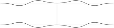
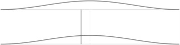
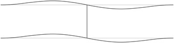
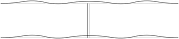
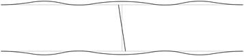
The displacement in the direction of the axis is represented in the normal direction to the pipe in the plane . The first transverse stability eigenmodes are presented in Fig. 2. The fifth and the sixth eigenmodes correspond to the same eigenvalue.
From the presented images of deflections the locations of measurement devices may be chosen.
Fig. 2The first transverse stability eigenmodes of the pipe system: a) the first eigenmode, b) the second eigenmode, …, j) the tenth eigenmode
a)
b)
c)
d)
e)
f)
g)
h)
i)
j)
4. Conclusions
The structure consisting from a lower straight pipe and an upper straight pipe both of them having fixed ends (all of the generalized displacements equal to zero) and filled with water is investigated. The midpoints of both pipes are connected by an empty pipe perpendicular to them. It is assumed that the fluid in the two pipes is flowing with given velocities. The first stability eigenmodes are obtained.
In order to perform precise measurements of stability of a pipe system the measurements are to be performed not at the nodes of the stability eigenmodes and preferably at the places with maximum deflections. The acceptable places of measurement are seen from the images of the stability eigenmodes.
References
-
Sudintas A., Paškevičius P., Spruogis B., Maskeliūnas R. Measurement of vibrations of a pipe system. Journal of Measurements in Engineering, Vol. 1, Issue 2, 2013, p. 101-105.
-
Sudintas A., Paškevičius P., Spruogis B. Transverse vibrations of a two-dimensional pipe system. Journal of Measurements in Engineering, Vol. 2, Issue 4, 2014, p. 185-189.
-
Bathe K. J. Finite Element Procedures in Engineering Analysis. Prentice-Hall, New Jersey, 1982.
-
Zienkiewicz O. C. The Finite Element Method in Engineering Science. Mir, Moscow, 1975, (in Russian).
-
Bolotin V. V. Vibrations in Engineering. Handbook, Vol. 1. Mashinostroienie, Moscow, 1978, (in Russian).
-
Prokofiev A., Makariyants G., Shakhmatov E. Modeling of pipeline vibration under the pressure ripples in the working fluid. 17th International Congress on Sound and Vibration, Cairo, Egypt, 2010, p. 1-8.
-
Lin Yih-Hwang, Tsai Yau-Kun Nonlinear vibrations of Timoshenko pipes conveying fluid. International Journal of Solids and Structures, Vol. 34, Issue 23, 1997, p. 2945-2956.
-
Murphy J. F. Transverse vibration of a simply supported beam with symmetric overhang of arbitrary length. Journal of Testing and Evaluation, Vol. 25, Issue 5, 1997, p. 1-3.
-
Zhang Y. L., Gorman D. G., Reese J. M. Analysis of the vibration of pipes conveying fluid. Proceedings of the Institution of Mechanical Engineers, Part C: Journal of Mechanical Engineering Science, Vol. 213, Issue 8, 1999, p. 849-860.
-
Chellapilla K. R., Simha H. S. Vibrations of fluid-conveying pipes resting on two-parameter foundation. The Open Acoustics Journal, Vol. 1, 2008, p. 24-33.
-
Liu L., Xuan F. Flow-induced vibration analysis of supported pipes conveying pulsating fluid using precise integration method. Mathematical Problems in Engineering, 2010, p. 1-15.
-
Maalawi K. Y., EL-Sayed H. E. M. Stability optimization of functionally graded pipes conveying fluid. World Academy of Science, Engineering and Technology, Vol. 79, 2011, p. 374-379.
About this article

