Abstract
Topicality of the problem is the fact that in the process of increasing the quality of line scale gage calibration vibrations have substantial influence. In order to assess vibration influence we need to solve a lot of science and engineering tasks. To accomplish mathematical analysis we confronted with a lot of difficulties in creating of the analytical model and in finding of the values of coefficients. For this solution we need to make thorough analysis of the means for line scale measurements, because most of the coefficients we could only find by making experimental measurements and processing of their results.
1. Introduction
Vibration measurements are widely applied in the evaluation or monitoring of measurement systems, the state of machinery and aggregates. Monitoring of measurement parameters and evaluation of their change in time, as well as taking appropriate actions according to the results of measurements helps to evaluate and remove sources of errors. The vibration measurement system performs these functions. Reliability of vibration measurement system in this case is understood as the probability of erroneous decision making, which it is necessary to minimize. This can be achieved by analyzing the factors affecting reliability.
The aim of the work is to create research methodology of evaluating and estimating of dynamic errors of precise comparator, and to investigate the influence of vibrations to the reading accuracy of the comparator with an error and uncertainty estimates. In order to reach the aims of the work it is necessary to solve these tasks:
• On the basis of scientific-technical literature to systematize all the knowledge in this field.
• To form dynamic and mathematical models of precise length measurement comparator system and to perform system modeling based on the experimentally found coefficients.
• To analyze dynamic errors of inherent reading, which are emerging because of the effects of vibrations, and to anticipate the compensation facilities of these errors.
•To investigate experimentally the impact of the results of vibration measurements at different measurement speeds, causing external excitation to the system and measuring vibrations at the time of calibration in order to determine the relationship between the vibration and accuracy of calibration.
• To establish dynamic errors and the methodology of assessment of uncertainty of results of vibration measurements.
Methodology of research includes carried out theoretical studies based on the theoretical mechanics, the vibration theory and the theory of measurements, using analytical, empirical and numerical research methods. The software “Matlab”, “Pulse” and “Origin” were used in the process of investigations.
Experimental material consists of data of the vibration measurement systems. The experiments were made at JSC Precizika Metrology in the Laboratory of Precision Line Scale Comparator. For measurement of parameters of vibrations measurement gauges produced by Bruel & Kjaer and Hottiger were used.
As a result of the performed research work the following new measurement results for the engineering science were obtained:
• The research methodology of dynamic errors of the comparator was created and consistent patterns of arising dynamic errors were determined (using the analytical, engineering and physical models), they enable to investigate precise system errors, resulting due to vibrations.
• The influences of the excitation and parameters of the dynamic system to the errors of calibration were determined.
Following the analysis of sources of literature and research of a number of theoretical and physical models, as well as the study of modern high-tech possibilities, comparator inherent errors arising from the influence of vibrations caused by many physical phenomena were determined: such as the vibration source of environment and the vibration source of the comparator.
The data obtained were used to assess the uncertainty of the results of vibration measurements and to investigate the errors, resulting from the influence of vibrations.
Length calibration systems and their errors were investigated. The length measurement calibration systems and their errors are analyzed, review of evaluation methodologies of calibration uncertainty is made, and evaluation of uncertainty of results of vibration measurements is performed.
According to the literature review it was found that for dynamic research of calibration systems little attention was devoted, especially:
• To set the dynamic errors of calibration system which has influence on quality of calibration, and to calculate their influence to quality of calibration [1-3];
• Research of system dynamics [4-6];
• Research of experimental line scale gage calibration in dynamic mode of vibration and assessment of uncertainty of calibration [7-9];
• The assessment of uncertainty of results of vibration measurements.
The status of current investigations of line scale comparators and related problems are presented in [10-16].
2. Dynamics of the line scale comparator
2.1. Description of the investigated line scale comparator
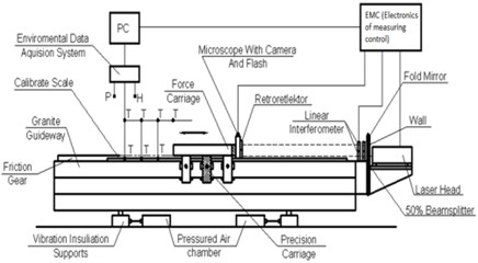
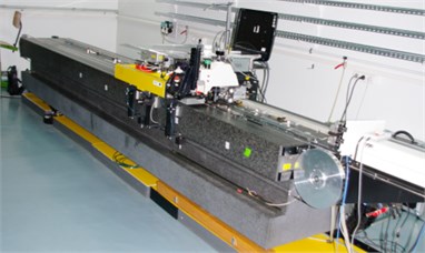
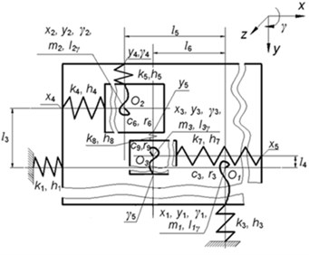
The investigated precise line gauge calibration comparator (Fig. 1) consists of nine main parts: laser type interferometer, gauge of measured environmental parameters, microscope with CCD camera, drive system, controller, data gathering and processing computer, correction system, granite guide ways, the carriage system consisting from the force carriage and the precise carriage.
Fig. 1The scheme a) and general view b) of the length measurement comparator
a)
b)
All parts of the length measurement comparator are interrelated and synchronized. The base part of the comparator is the massive fine structure granite frame of the 4 m length with guide ways, which in the horizontal plane is placed on four pneumatic supports. Those supports perform the damping of high frequency oscillations. The carriage system moves along the frame guide ways. The carriage system is designed in such a way, that carriages are located on stiffly mounted aerostatic supports, which are preloaded with the help of supports mounted in the opposite sides. The mounting of the supports is designed in such a way that they have a possibility to spring. This enables to adjust required small clearances in aerostatic supports and to increase the rigidity of the structure.
2.2. Dynamic model of the investigated line scale comparator
It was concluded that the investigated line scale comparator may be represented by the dynamic models of the total comparator and separately of the carriage. Comparator dynamic model is shown in Fig. 2.
Fig. 2Dynamic model of the comparator for precise length measurment
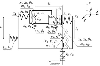
a) The view in the plane
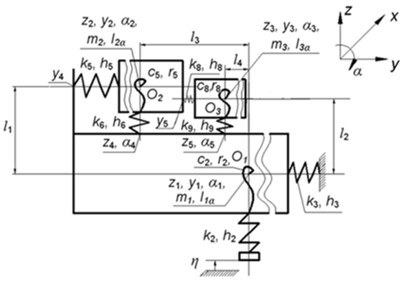
b) The view in the plane
c) The view in the plane
Explanations of notations used in Fig. 2: , , are origins of coordinate systems of separate subsystems of the model, they coincide with mass centres of corresponding parts; , , are their mass centers; , , are their moments of inertia, where corresponds to twisting angles , , ; are coefficients of rigidity according to the linear axes of motion ( 1, ..., 9); are coefficients of rigidity according to the angular motion coordinates ( 1, ..., 9); are damping coefficients according to the linear axes of motion ( 1, ..., 9); are damping coefficients for angular motions ( 1, ..., 9); expresses the kinematical excitation function (oscillations of the foundation).
The precision length comparator is a complicated mechatronic system, for correct evaluation of which dynamic researches should be performed. In order to derive differential equations of this system it is recommended to use the Lagrange equations of the second type.
The mathematical model of the total system will compose the system of differential equations of the second order and algebraic constraint equations. The differential equations are represented in the form:
where , , are matrices of inertia, damping and rigidity; , , are vectors of generalized displacements, velocities and accelerations, is the vector of generalized external forces.
For the investigated system the matrixes , , are symmetric and non negative definite and the matrix is positive definite.
2.3. Determination of the spectral densities of the comparator
Fourier transform of the equation describing the dynamics of the comparator has the form:
where is the frequency, is the imaginary unit, is the Fourier transform of , is the Fourier transform of .
This equation can also be written as:
where:
For calculation of spectral densities the conjugate function is also required:
Spectral densities of the excitation and of the response are related as:
where is the matrix of spectral densities of response (generalized displacements) and is the matrix of spectral densities of excitations (generalized forces). By solving this equation for a number of values of the frequency variable spectral densities of response can be determined. But by performing some simplifications the calculation of spectral densities of response can be performed more efficiently.
When damping is small and the exact results at resonances are not of primary importance damping can be neglected. In this case the expression of can be simplified and has the form:
But in order to perform calculations more efficiently the eigenmodes of the undamped system are used. When there is no excitation and no damping, the equation of dynamics of the system has the form:
Solutions of this equation have the form:
Then the equation is expressed as:
By solving this eigenvalue problem the eigenfrequencies and the eigenmodes are obtained, here and is the number of degrees of freedom of the structure. The eigenvectors are stored in a matrix:
The scale of the eigenmodes is chosen so that the foolowing condition is satisfied:
Then the conditions of orthogonality hold:
where is the identity matrix and:
The motion is expressed by the linear combination of the eigenmodes:
where is the vector of the coefficients of the eigenmodes , ,…,
Modal equations have the form:
The following notation is introduced:
In order to decouple the modal equations the non diagonal elements of this matrix are ignored. Then the modal equations have the form:
where the modal damping is expressed as:
where denotes the th diagonal element of the matrix
The following notation is introduced:
Thus the modal equation has the form:
Fourier transform of the modal equation has the form:
where is the Fourier transform of , is the Fourier transform of
This equation can also be written as:
where:
For calculation of spectral densities the conjugate function is also required:
Spectral densities of the modal excitation and of the modal response are related as:
where is the spectral density of modal response and is the spectral density of modal excitation.
It is assumed that damping is small and there are sufficient intervals between the eigenfrequencies. Thus:
or:
By taking into account that:
where is the frequency measured in Hz, it follows that:
Spectral densities of modal excitations and spectral densities of excitations are related by:
where is the matrix of spectral densities of modal excitations.
Spectral densities of modal responses and spectral densities of responses are related by:
where is the diagonal matrix of spectral densities of modal responses.
On the basis of the presented relationships the spectral densities of the comparator are investigated.
2.4. Results of investigation of dynamics of the comparator
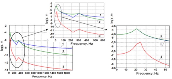
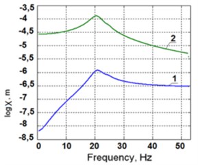
The system response to the most important excitation – the force added to the force carriage, is shown in Fig. 3(a). There are seen two zones of resonances on the frequency curves: the zone of 20-25 Hz and the zone of 280-310 Hz. The error depends on the actual amplitude of the excitation force. In the investigation and presented results it is assumed as the unit force.
Fig. 3Amplitude frequency response to the excitation added to the force carriage in the y2 direction a): of the precise carriage along the coordinate y3 (1), of the force carriage along the coordinate y2 (2), of the frame along the coordinate y1 (3); amplitude frequency response to the excitation added to the force carriage in the y2 direction b)
a)
b)
Amplitude frequency characteristics of oscillations of the force in the carriage with respect to the precise one (1) and of oscillations of the frame with respect to the precise carriage (2) are shown in Fig. 3(b) (of the force in the carriage with respect to the precise carriage, - (1), of the precise carriage with respect to the frame, - (2)).
In the picture two zones of resonances on the frequency curves can be seen: the zone of 20-25 Hz and the zone of 280-310 Hz. The error depends on the actual amplitude of the excitation force. Here it is assumed as the unit force. Modes of oscillations falling into these zones are shown in Fig. 3(a). It is seen, that the oscillations along the coordinates and are taking place at these frequencies in a counteraction manner.
3. Experimental dynamic research of line scale comparator
The aim of these studies is to determine calibration errors caused by the mechanical instability of the system. They occur in cases when:
• the distance between the point where the optical axis of the microscope intersects with the plane of the scale lines and carriage point displacement of which is measured by laser interferometer changes;
• the carriage speed changes in the direction of measurement of motion during photographic registration of lines.
In order to clarify reasons causing these factors and the degree of their impact to the positioning error the following studies of dynamic stability of mechanical system of the comparator have been made:
• vibrations of the concrete foundation in horizontal and vertical directions which excite vibrations of the comparator were specified (more exactly);
• vibrations of the comparator base – granite guide ways in the direction along guide ways and in the vertical direction were specified (more exactly);
• vibrations of the characteristic points of the carriage under excitations of impact type were investigated;
• vibrations of the carriage point where the microscope is attached, as well as relative vibrations of the microscope and mirror of the laser interferometer, which is fixed to the carriage under the following conditions:
a) all pneumatic systems are switched off;
b) pneumatic vibration insulation supports are switched off;
c) all pneumatic systems are switched on;
d) measurements are performed on the working speed, smaller speed than the working speed, faster speed than the working speed;
e) motion is carried without electrical actuators.
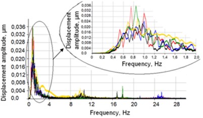
Fig. 4Graphs of absolute vibrations a) of point D and vibration spectrum b) in the longitudinal direction: 1 – all pneumatic systems and the drive are switched off; 2 – all pneumatic systems are switched off and the drive is switched on; 3 – vibration insulation supports are switched on, but no air is in the air bearings of the carriage and the drive is switched on; 4 – all pneumatic systems and the drive are switched on; 5 – all pneumatic systems are switched on and the drive is switched off
a)
b)
Velocities of carriage oscillations at different speeds of movement were investigated: with the aim to investigate the influence of the drive to the mechanical system of the comparator for length measurement, the drive mounting position was replaced and the friction drive was changed into the rope drive.
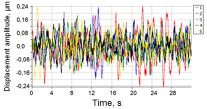
The results of measurements and analysis of the vibrations of the carriage in the static state are shown in Fig. 4, and the obtained results provide the basis for design of the investigated system.
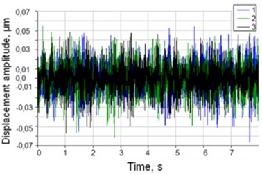
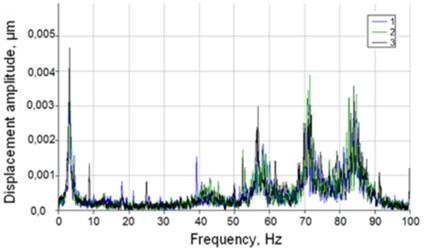
When the carriage moves with the working speed of 3 mm/s and less, the obtained results are given in Fig. 5 (1 – carriage speed 1 mm/s, 2 – carriage speed 2 mm/s, 3 – carriage speed 3 mm/s).
Fig. 5Graphs of relative vibrations of the laser microscope with respect to the mirrors of the laser interferometer a) and spectrum of vibrations b)
a)
b)
4. Conclusions
1. On the basis of the references about qualitative analysis of precise line scale measuring comparators, it can be concluded that the influence of dynamics to the accuracy of calibration of the comparator is insufficiently researched. Particularly error components due to vibrations and its weight are not evaluated in the total uncertainty budget.
2. After creating the mathematical model for the comparator dynamics and after performing the computer experiments according to the proposed model and verification of it by realistic tests it was shown:
2.1. It was determined that when the seismic excitation from the ground acts to the comparator with realistic values of oscillation amplitudes, values of vibration amplitudes are small (till 0.1 µm) and they do not have a significant impact on the dynamic performance characteristics of the system.
2.2. It is found that the oscillations of the precision and force carriages at resonant frequencies 24 Hz and 296 Hz are taking place in opposite directions and they can be harmful.
3. It was determined experimentally that the biggest influences to generation of vibrations have: the design of the carriages of the comparator and of the drive submitting the motion to the force carriage.
4. It is found that the influence of vibrations to the calibration error is smallest, when the speed of carriage of the comparator is 3 mm/s.
5. Regularities of the occurrence of dynamic errors associated with the position of the drive mounting were clarified: after replacing the drive system to the granite guide ways, frequency of absolute vibrations of the system decreases from 10 Hz till 3 Hz, at which the amplitude of the dominant vibrations is the highest.
References
-
Kasparaitis A., Vekteris V., Kilikevičius A. Line scale comparator carriage vibrations during dynamic calibration. Journal of Vibroengineering, Vol. 10, Issue 3, 2008, p. 347-354.
-
Kasparaitis A., Vekteris V., Kilikevičius A. Precision measurement of the carriage vibrations at the different speeds. Solid State Phenomena, Vols. 147-149, 2009, p. 690-695.
-
Kausinis S., Kasparaitis A., Barakauskas A., Barauskas R., Jakstas A., Kilikevicius A. Line scale calibration in non-ideal measurement situation. Solid State Phenomena, Vols. 147-149, 2009, p. 682-685.
-
Kilikevičius A., Vekteris V. Diagnostic testing of the comparator carriage vibrations. Ultragarsas, Vol. 2, Issue 59, 2006, p. 26-30.
-
Kasparaitis A., Vekteris V., Kilikevičius A. Investigation of vibrations acting on mechatronical comparator. Ultragarsas, Vol. 1, Issue 62, 2007, p. 38-41.
-
Kilikevičius A., Sabaitis D. Stability of length measurement comparator’s carriage generative unnatural excitation. Ultragarsas, Vol. 1, Issue 63, 2008, p. 33-37.
-
Vekteris V., Kilikevičius A., Jurevičius M., Striška V. Comparison of the comparator carriage vibration velocity measurement methods. Matavimai, Vol. 2, Issue 40, 2007, p. 24-27.
-
Trumpa A., Vekteris V., Kilikevičius A., Striška V. Diagnostics of the centrifugal milk separator. Matavimai, Vol. 2, Issue 40, 2007, p. 21-23.
-
Kilikevichius A., Vekteris V. Research of vibrations acting the comparators carriage. Journal Materials, Methods and Technologies, Vol. 2, Issue 1, 2008, p. 11-23.
-
Abbe M., Starrenburg M. P., Sawaabe M. Results from step gauge calibration using bi-axial laser interferometer. Proceedings of the 6th ISMQC IMEKO Symposium on Metrology for Quality Control in Production, Vienna, 1998, p. 9-13.
-
Korolev A. N., Gartsuev A. I., Polishchuk G. S., Tregub V. P. Metrological studies and the choice of the shape of an optical mark in digital measuring systems. Journal of Optical Technology, Vol. 77, Issue 6, 2010, p. 370-372.
-
Shirmohammadi S., Ferrero A. Camera as the instrument: the rising trend of vision based measurement. IEEE Transactions Instrumentation Measurement, Vol. 17, Issue 3, 2014, p. 41-47.
-
Acko B. Calibration of measuring instruments on a coordinate measuring machine. Advances in Production Engineering and Management, Vol. 2, Issue 3, 2007, p. 127-134.
-
Kovac I., Frank A. Testing and calibration of coordinate measuring arms. Precision Engineering, Vol. 252, 2001, p. 90-99.
-
Acko B. Uncertainty of thread gauge calibration by using a coordinate measuring machine. Strojarstvo, Vol. 10, Issue 1, 2004, p. 5-10.
-
Jens Flugge, Rainer Koning, Harald Bosse Recent activities at PTB nanometer comparator. Proceedings of SPIE 5190, Recent Developments in Traceable Dimensional Measurements II, 2003, p. 391.
About this article

