Abstract
The vision-based structural displacement measurement technology is an advanced non-contact means for structural vibration monitoring. In the practical applications, different kinds of sources will affect the measurement accuracy of the vision-based displacement measurement system. In this study, the effect of the environmental factor on the operational performance of the vision-based displacement measurement system is investigated. Comparative analyses of the results obtained from the experiments with various types of vapor levels and vision targets (quick response (QR) codes and infrared emitters) indicate that the environmental factor has a significant effect on the system performance and measurement accuracy of the vision-based displacement measurement system.
1. Introduction
Civil engineering structures are prone to vibrate under the external stochastic loadings (e.g., wind, earthquake, wave, and traffic), which will result in fatigue damage and cracking in critical structural components. Structural vibration monitoring is a critical task for developing damage identification methods and establishing vibration control strategies [1]. Structural dynamic displacement is an important indicator for evaluation of the vibration characteristics of civil infrastructure. Amongst the currently-available structural vibration monitoring approaches, the vision-based structural displacement measurement method has attracted increasing attentions because of its advantages of non-contact, long-distance, high-precision, anti-electromagnetic interference, and multi-object synchronous measurement [2, 3].
In the real applications, the measurement performance of the vision-based system will be affected by some certain factors, such as the lens distortion, correlation functions, self-heating of the digital camera, shape functions, etc. [4-7]. However, in the field measurement, various kinds of environmental factors may be major obstacles encountered by the vision-based displacement measurement. In this paper, a vision-based system is developed for multi-point structural displacement measurement. The system software is configured by use of the LabVIEW graphical programming language. Laboratory experiments on a shaking table for investigation of the environmental effect on the system performance are conducted with different vapor levels and vision targets.
2. Methodology
The theoretical basis of the vision-based multi-point structural displacement measurement system is the methodology of digital image processing [8]. The algorithm of multi-point pattern matching is the main component which is able to effectively locate the target in an image by matching the predefined pattern. The pattern with a certain identifiable target is firstly set up and then it will be picked up to match the subsequent images captured by the digital camera. The score on the basis of the multi-point pattern matching algorithm will be calculated [9, 10]. When the score reaches the maximum value, the pattern best corresponds with the target in the original image and the position of the predefined target is detected with the pattern matching algorithm and signal processing technique.
The customized system software for vision-based structural displacement measurement is developed with the aid of the LabVIEW graphical programming language. Fig. 1 shows the interface of the vision-based multi-point structural displacement measurement system. As illustrated in Fig. 1(a), an image with the identifiable targets (P1 and P2) is captured by the digital camera and the patterns (pattern 1 and pattern 2) are corresponding to the targets (P1 and P2). Meanwhile the initial coordinate (, ) of the center of the pattern ( 1, 2) is recorded. With the pixel coordinate difference between P1 and P2, , and the actual distance between P1 and P2, , a scale ratio is expressed by:
With the pattern matching algorithm, the patterns will be best matched in the succeeding images captured by the digital camera at time when the score of pattern matching reaches the maximum value. Then the coordinate of the center of the overlapped part between the image and the pattern, (, ) is obtained. Thus the structural displacement can be calculated by:
In this software, a region of interest (ROI) is used to improve the matching speed and operational efficiency. By presetting the ROI, the pattern matching and searching task are completed in a smaller region instead of the whole image area so that the execution of the pattern matching is more effective.
In this study, the hardware of the vision-based multi-point structural displacement measurement system consists of a high-resolution industrial charge-coupled device (CCD) camera, a zoom lens, a computer, and a Gigabit Ethernet standard LAN wire. In this system, a Prosilica GE1050 camera with a Navidar 12X zoom extender lens serves as the image acquisition equipment, as illustrated in Fig. 2.
Fig. 1Vision-based multi-point displacement measurement system software
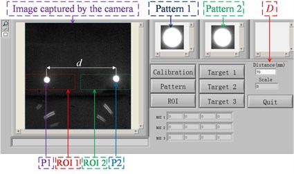
a) Configuration interface
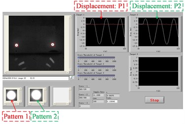
b) Real-time monitoring interface
3. Experimental study
In the practical applications, the environmental factor like foggy weather may have effects on the structural displacement measurement with the vision-based system. In this study, a series of experiments on a shaking table are conducted to explore the effect of vapor. Cases with two kinds of vision targets and two vapor levels are designed as listed in Table 1. The vapor is produced by a humidifier to simulate the foggy weather, and the vapor level is controlled by the knob of the humidifier. The effect of the vapor on the measurement accuracy of the vision-based system is investigated through a comparative study between the vision-based system and the traditional displacement measurement sensor, i.e., magnetostrictive displacement sensor (MDS). The comparative experiments are operated on a self-made shaking table on which a rigid board attached with two kinds of vision targets (quick response (QR) codes and infrared emitters) is fixed. The vibration frequency of the shaking table is 0.3 Hz and the sampling frequency of the two systems is 10 Hz. The distance between the digital camera and the targets is 2 m. The experimental setup is shown in Fig. 2.
Table 1Cases for experiments
Case | Vision target | Level of vapor |
Case 1 | QR code | 1st |
Case 2 | QR code | 2nd |
Case 3 | Infrared emitter | 1st |
Case 4 | Infrared emitter | 2nd |
Fig. 2Experimental setup
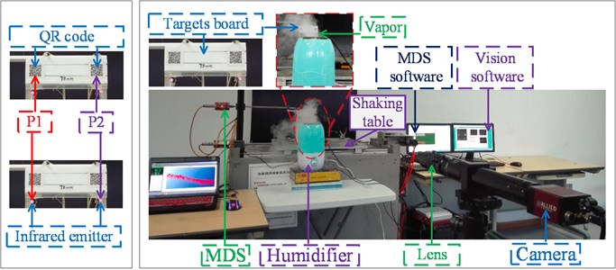
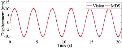
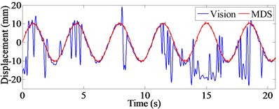
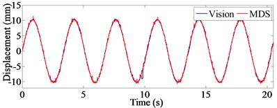
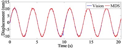
Fig. 3Displacement time histories of case 1

a) P1
b) P2
Fig. 4Displacement time histories of case 2
a) P1
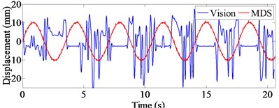
b) P2
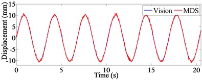
Figs. 3-6 illustrate the displacement time histories of P1 and P2 measured by the vision-based system and the MDS in the aforementioned four cases. It is shown that for the vision target of QR code, the level of vapor have a great effect on the measurement accuracy of the vision-based system through the comparison analysis between Fig. 3 and Fig. 4. There are many errors in the displacement time histories of case 2 in the second level of vapor as illustrated in Fig. 4. However, for the vision target of infrared emitter, as illustrated in Figs. 5-6, the effect of the vapor on the measurement accuracy of the vision-based system is not significant, which indicates that the infrared emitter may be a better choice as the vision target in the foggy weather.
Fig. 5Displacement time histories of case 3
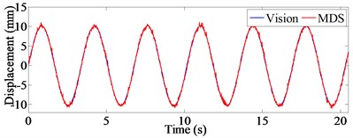
a) P1
b) P2
Fig. 6Displacement time histories of case 4
a) P1
b) P2
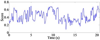
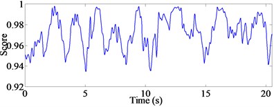
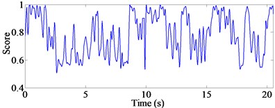
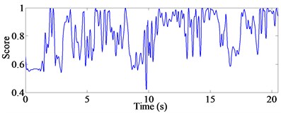
To further explore the effect of the vapor, the scores calculated by the algorithm of pattern matching are extracted. Figs. 7-10 illustrate the score time histories of the pattern matching of P1 and P2 in the aforementioned four cases. It is seen from Fig. 7 and Fig. 8 that the higher vapor level makes the score of pattern matching decreased with the QR code as the vision target, which means that the matching process is not good leading to unsatisfactory measurement accuracy. Table 2 shows the average value, , and the standard deviation, of the score time histories. It is also concluded that the vapor has a significant effect on the pattern matching of the vision-based system when the QR code is used as the vision target. In addition, the infrared emitter has a better anti-interference ability to the vapor effect than the QR code in vision-based multi-point structural displacement measurement.
Fig. 7Score time histories of case 1
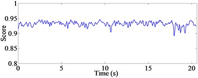
a) P1
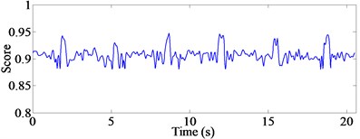
b) P2
Fig. 8Score time histories of case 2
a) P1
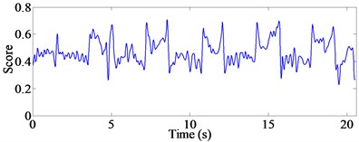
b) P2
Fig. 9Score time histories of case 3
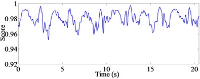
a) P1
b) P2
Fig. 10Score time histories of case 4
a) P1
b) P2
Table 2Statistical analysis of score time histories
Target | QR code | Infrared emitter | ||||||
Case | 1 | 2 | 3 | 4 | ||||
Level of vapor | 1st | 2nd | 1st | 2nd | ||||
Point | P1 | P2 | P1 | P2 | P1 | P2 | P1 | P2 |
Average value | 0.9317 | 0.9071 | 0.4255 | 0.4693 | 0.9806 | 0.9726 | 0.7840 | 0.8104 |
Standard deviation | 0.0078 | 0.0116 | 0.1321 | 0.0853 | 0.0087 | 0.0153 | 0.1427 | 0.1409 |
4. Conclusions
In this paper, a vision-based multi-point structural displacement measurement system is developed for structural vibration monitoring in a non-contact manner. The system software is customized based on the LabVIEW graphical programming language. Experimental study of the influence factor (vapor) indicates that the system performance of the developed vision-based system will be affected by the foggy weather. The vision target of the infrared emitter has a better anti-interference ability to the vapor effect than the QR code in the vision-based multi-point structural displacement measurement. In the further investigation, field tests will be carried out to validate the accuracy and stability of the developed vision-based system.
References
-
Le T. P., Paultre P. Modal identification based on continuous wavelet transform and ambient excitation tests. Journal of Sound and Vibration, Vol. 331, 2012, p. 2023-2037.
-
Henke K., Pawlowski R., Schregle P., Winter S. Use of digital image processing in the monitoring of deformations in building structures. Journal of Civil Structural Health Monitoring, Vol. 5, 2015, p. 141-152.
-
Park S. W., Park H. S., Kim J. H., Adeli H. 3D displacement measurement model for health monitoring of structures using a motion capture system. Measurement, Vol. 59, 2015, p. 352-362.
-
Yoneyama S., Kikuta H., Kitagawa A., Kitamura K. Lens distortion correction for digital image correlation by measuring rigid body displacement. Optical Engineering, Vol. 45, Issue 2, 2006, p. 023602.
-
Schreier H. M., Sutton M. A. Systematic errors in digital image correlation due to under matched subset shape functions. Experimental Mechanics, Vol. 42, Issue 3, 2002, p. 303-310.
-
Ma S. P., Pang J. Z., Ma Q. W. The systematic error in digital image correlation induced by self-heating of a digital camera. Measurement Science and Technology, Vol. 23, Issue 2, 2012, p. 025403.
-
Yu L. P., Pan B. The errors in digital image correlation due to overmatched shape functions. Measurement Science and Technology, Vol. 26, Issue 4, 2015, p. 045202.
-
Ye X. W., Ni Y. Q., Wai T. T., Wong K. Y., Zhang X. M., Xu F. A vision-based system for dynamic displacement measurement of long-span bridges: algorithm and verification. Smart Structures and Systems, Vol. 12, Issues 3-4, 2013, p. 363-379.
-
Ye X. W., Yi T. H., Dong C. Z., Liu T., Bai H. Multi-point displacement monitoring of bridges using a vision-based approach. Wind and Structures, Vol. 20, Issue 2, 2015, p. 315-326.
-
Gonzalez R. C., Woods R. E. Digital Image Processing. Third Edition, Pearson Prentice Hall, Upper Saddle River, New Jersey, 2008.
About this article

The work described in this paper was jointly supported by the National Science Foundation of China (Grant No. 51308493) and the Research Fund for the Doctoral Program of Higher Education of China (Grant No. 20130101120080).
