Abstract
Studies of shock waves from explosions involve the dynamic analysis of geometric, material, and contact nonlinearities. The action of the shock wave on soil (pressurization and decompression) is completed within milliseconds. The energy transfer process of shock waves has a significant impact on engineering structures; an analyst evaluating the effectiveness of safety measures must first understand the dynamic characteristics of this energy transfer. Thus, examining the movement patterns of the media through which shock waves travel is of primary concern. Construction designs must consider the propagation characteristics of shock waves in soil. In this study, the finite element method was employed to analyze the dynamic and mechanical behavior of soil by applying the multi-material arbitrary Lagrangian-Eulerian algorithm to a 3D solid element with eight nodes and six faces. A structural model of the fluid-solid coupling was constructed to examine the shock wave propagation process resulting from shallow underground explosions. In addition, ground surface acceleration values obtained from field tests were used to validate results of the numerical analysis of time- and space-dependent shock wave propagation and attenuation in soil. The objective of this study was to perform a rational analysis of the seismic effects of shallow underground explosions to provide a reference for earthquake engineering.
1. Introduction
Explosions rapidly release energy, causing a sudden increase in temperature and pressure in the surrounding medium, resulting in a phenomenon known as overpressure. Blast waves cause surface particles to vibrate, and the inertia affects material stability. Seismic waves in the ground are primarily produced by shock waves in the air. A seismic wave first propagates in the form of a shock wave, which is later converted to an elastic seismic wave, causing surface particles to vibrate [1, 2]. Surface vibrations from a shallow underground explosion form a spherical shock wave in the soil. Shock waves near the blast source exhibit high velocity and magnitude, resulting in higher velocity and magnitude in the corresponding soil compression wave [3]. With the same charge weight, the error of margin of the peak blast pressure is 15 % compared with experimental values [4]. In shallow explosions, the blast pressure compresses the soil, forming a crater and creating shock waves in both the air and soil. If a charge is buried deep underground, as is the case in drilling and blasting, the blast effect is insufficient to displace the soil. Thus, the detonation cannot directly create a shock wave in the air, and a shock wave forms only in the soil [5]. The mechanical behavior of an explosion is complex; the load time is short and the vibration frequency is high. For surface or shallow underground explosions, the magnitude of destruction is analyzed on the basis of the magnitude of surface vibrations.
The seismic effect of an explosion refers to the seismic phenomenon generated in a defined area as a result of the detonation of a charge within a geological environment. Crandle [6] analyzed the propagation of blast waves and found that when seismic waves produced by an explosion propagate through a medium, the surrounding particles vibrate in response to the process. When the vibration reaches a specific magnitude, structures within a defined area are affected to varying degrees, even to the point of destruction. Koga and Matsuo [7] examined the detonation of charges in surface soil and found that a portion of the energy is released as waves traveling outward through the medium. In the propagation process, a portion of the energy is converted into seismic waves that cause the particles in the medium to vibrate, resulting in vibration on the ground surface. Pullen et al. [8] constructed a simple soil composition model in DYNA2D, a hydrodynamic finite element code, to simulate the propagation behaviors of a complex stress wave. Analysis results of the initial pressure, strain, and impulse roughly corresponded to the experimental results.
The seismic effect of an explosion causes surface particles to vibrate. The motion characteristics of the medium are key parameters affecting the blast load. Particle displacement, velocity, and acceleration can be applied to evaluate the basic parameters of the vibration effect. Because an underground explosion causes surface vibrations, geological structures are subjected to time-dependent effects such as displacement, velocity, acceleration, stress, and deformation. Inertia, which is produced by resistance to the acceleration of a structure with mass, affects the stability of the structures. In studies that have analyzed explosions or earthquakes, the vibrational velocity, acceleration, and displacement of particles have been used as physical parameters to assess the magnitude of blast vibrations [9-12]. In the present study, a numerical analysis model was constructed and validated by using ground surface acceleration readings obtained through explosion field experiments. The energy of the shock waves caused by shallow underground explosions and the area of effect were also analyzed. The results may serve as a reference for antiblast safety engineering.
2. Shallow underground explosion field experiment
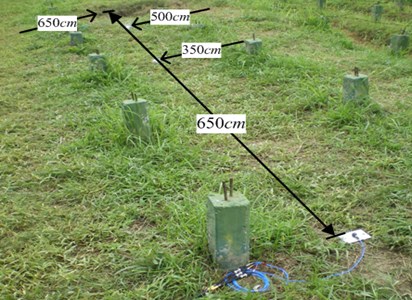
Fig. 1 shows the configuration of the field site for the explosion field experiment. The experiment used 0.25 lb (113.389 g) of TNT buried 30 cm beneath the ground surface. Triaxial accelerometers were placed 350, 500, and 650 cm from the center of the charge to measure the ground surface acceleration in the , , and directions for a quantitative analysis of the propagation and attenuation of the ground surface motion caused by the underground explosions. Oscilloscopes, signal conditioning processors, power supplies, and data acquisition systems were also used in the field experiments. The signals produced must pass through signal conditioning processors linked to an oscilloscope for signal transmission and storage.
Fig. 1Configuration of the explosives in the field experiment
3. Finite element analysis methods
LS-DYNA, a nonlinear finite element analysis code based on continuum mechanics theories, was employed to analyze the shallow underground explosions and the resulting propagation of blast waves in soil. LS-DYNA primarily uses an explicit time-integration method to solve dynamic time-integration problems and is a conditionally stable calculation method. Explicit time-integration methods are based on the d’Alembert principle. The single degree-of-freedom elastic damping system is expressed in Eq. (1), a nonlinear system is expressed in Eq. (2), and the matrix equation for the motion with multiple degrees of freedom is expressed in Eq. (3). This code is advantageous because it can be used to analyze nonlinear and large deformation behaviors in 3D structures, and is particularly suitable for solving nonlinear dynamic problems such as high-velocity collisions and explosions [13]:
where represents mass; denotes damping; refers to stiffness; represents acceleration; is velocity; represents displacement; denotes external forces matrix; represents the acceleration matrix for the node; is the velocity matrix for the node; denotes the displacement matrix for the node; represents the external forces matrix; is the mass matrix; refers to the damping matrix; and is the stiffness matrix.
Explicit time-integration based on the central difference scheme is suitable for solving nonlinear problems. The method assumes the relationships among acceleration, velocity and shifting are expressed in Eqs. (4) and (5), respectively. The variance between the above two equations is . To find the answer for shifting at the time , consider the dynamic equation for time (), as shown in Eq. (6). Apply procedures Eqs. (4) and (5) in (6), as shown in Eq. (7). Procedure Eq. (8) reveals that is apparently derived from the shifting of the previous time; only the balance conditions at time () need to be taken into consideration. This is the benefit of explicit time integration:
where represents the acceleration matrix for a node at time ; is the velocity matrix for a node at time ; and is the displacement matrix for a node at time .
Explicit time-integration requires a time-step to be smaller than the critical time interval; this is the conditional stability of explicit time-integration. However, is calculated differently for different element types. When calculating time , LS-DYNA automatically divides into cycles; thus, the time required for code calculations depends on . In this study, a solid element comprising eight nodes was used; the conditions for stability are expressed in Eqs. (8) and (9), and the characteristic length is given in Eq. (10). The propagation of velocity in an elastic material with a constant bulk modulus is shown in Eq. (11). The LS-DYNA user’s manual suggests using a time-step control coefficient smaller than 0.67 when analyzing blast effects [14]:
where is the function of volume viscosity coefficients and ; is the characteristic length; is the strain rate tensor; is the element volume; is the area at the longest side; is the sonic velocity in materials; is the density; is Young’s modulus; is shear modulus and is Poisson’s ratio.
3.1. Numerical computational model
In this study, the multi–material arbitrary Lagrangian-Eulerian (MMALE) algorithm was employed to analyze the time history of shock wave dynamic reactions produced by the shallow underground explosion of TNT. To construct a numerical analysis model of the fluid-solid coupling, the explosives and air were defined as a Eulerian grid and the soil as a Lagragian grid. The numerical analysis involved a 3D solid element with eight nodes and six faces, as well as explosives, air, and soil defined as MMALE grids. The fluid and solid grids were independent of each other. The fluid–solid coupling was constructed by overlapping the grids. The setting CONSTRAINED_LAGRANGE_IN_SOLID was applied to construct a numerical analysis model of the fluid-solid coupling based on the MMALE algorithm. This model enabled the analysis of the time- and space-dependent propagation and attenuation of shock waves in the soil.
Fig. 2 shows a quarter-symmetry model used for numerical analysis. The numerical analysis model was constructed according to the explosion field test conditions by using the following units: , , . To exploit the symmetry of the model, a quarter-symmetry model with nonreflecting boundary conditions was used for the analysis. For the field experiment, the rectangular TNT charges weighed 0.25 lb (113.389 g) and had a density of 163 g/cm3. In the quarter-symmetry model, the dimensions of the charges were 1.64×1.64×9.3 cm. The charges were buried at a depth of 30 cm and the detonation point was located at the center of the charge. Air was defined as an ideal gas. The ideal gas law was applied with the dimensions of 190×660×120 cm in the quarter-symmetry model. The dimensions of the soil in the model were 180×660×120 cm. Based on the convergence analysis of the numerical model, the grid density was defined as the smallest width of the TNT; the Eulerian grid was defined as 0.5-fold the smallest side of the charge; and the time-step control coefficient was defined as 0.3 [13, 14].
Fig. 2Quarter-symmetry model used in the numerical analysis
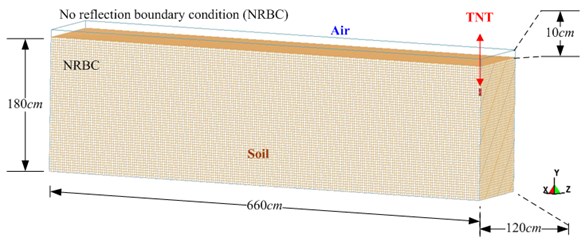
Table 1 lists the material parameters for the explosives, air, and soil. To model the air, the material identified as #9 (MAT_NULL), in the LS-DYNA code was combined with the EOS_LINEAR_POLYNOMIAL EOS to describe the characteristics of the material, as shown in Eq. (12) [14]. The parameters used were density (RO), pressure cutoff (PC), dynamic viscosity coefficient (MU; ), relative volume (TEROD and CEROD), Young’s modulus (YM), Poisson’s ratio (PR), initial energy per unit volume (), and , , , , , are constants. For ideal gases, the coefficients in the LINEAR_POLYNOMIAL EOS are , , , and . The EOS is expressed in Eq. (13). The parameters used were represents the rate of change to the specific air temperature, represents the current air density, is the initial air density value and denotes the relative density:
Table 1Material parameters of soil, air, and TNT explosive
Element | Material and equation of state parameters (unit system: g, cm, μ-second) | ||||||
Soil | MAT_SOIL_AND_FOAM | ||||||
RO | BULK | PC | |||||
2.6 | 0.000147 | 0.00729 | 7.105E-07 | 4.198E-08 | 6.215E-10 | 0.0 | |
Air | MAT_NULL | ||||||
RO | PC | MU | TEROD | CEROD | YM | PR | |
0.00129 | 0.0 | 0.0 | 0.0 | 0.0 | 0.0 | 0.0 | |
EOS_LINEAR_POLYNOMIAL | |||||||
, , , | |||||||
–1.07E-06 | 0.0 | 0.4 | 0.4 | 1.0 | 2.53E-06 | ||
TNT | MAT_HIGH_EXPLOSIVE_BURN | ||||||
RO | PCJ | BETA | SIGY | ||||
1.63 | 0.693 | 0.21 | 0.0 | 0.0 | 0.0 | 0.0 | |
EOS_JWL | |||||||
OMEGA | |||||||
3.712 | 0.03231 | 4.15 | 0.95 | 0.3 | 0.07 | 1.0 | |
To model the explosives, the material identified as #8 (MAT_HIGH_EXPLOSIVE_BURN), in LS-DYNA was combined with the Jones-Wilkins-Lee (JWL) EOS to describe the characteristics of the high explosives, as shown in Eq. (14) [15]. Relevant parameters taken from the Lawrence Livermore National Laboratory Explosives Handbook [16] were the density (RO) of the material, detonation velocity (), Chapman-Jouget pressure (PCJ), beta burn flag (BETA), bulk modulus (), shear modulus (), and yield stress (SIGY). The parameters for the EOS were relative volume (), initial energy per unit of volume (), and internal energy of the material (); , , , , and were constants representing the characteristics of the explosives:
Soil is a compressible porous material. The Krieg yield criterion is based on the theory of isotropic elasticity, which states that the behavior of materials at the yield point can be differentiated into hydrostatic pressure and shear stress. This model is suitable for analyzing material failure under stress. The yield function () is expressed in Eq. (15). LS-DYNA was used to calculates the shear failure criterion according to the relationship between the average stress and extent of damage [17]. The material model MAT_SOIL_AND_FOAM in LS-DYNA was used to analyze the dynamic conditions of soil after being subjected to blast effects [14, 15]. The soil parameters were density (RO), shear modulus (), bulk modulus (), pressure cutoff () and , , is the yield function constant for plastic yield function below. Indoor experiments of the soil showed that its water content was 11.8 %, 8.43 kPa, and 14°. Under the Unified Soil Classification System, this soil was classified as SP-SM, which is poorly graded sand containing silt:
with , , . Where is the second invariant of the deviatoric stress; is the pressure; and , , are the parameters related to the shear on the yield surface.
4. Results and discussion
4.1. Analysis of vibrations recorded in the explosion field test
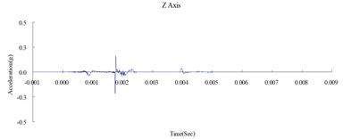
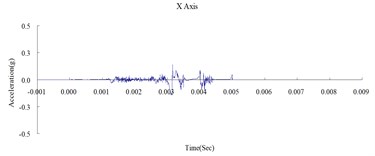
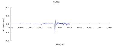
This study was conducted to analyze the propagation characteristics of shock waves and the dynamic reactions of the ground surface caused by shallow underground explosions, as well as to use the quantitative readings of ground surface acceleration to verify the results of the numerical analysis. To determine the blast-wave propagation characteristics, the ground surface acceleration was measured at 350, 500, and 650 cm horizontally from the surface of the detonation. Table 2 shows the peak ground surface acceleration at points along the , , and axes. Figs. 3, 4, and 5 show the acceleration time history of the ground surface acceleration at 350, 500, and 650 cm from the blast source, respectively. The results show that given the same charge weight, the vertical ground surface acceleration is faster than the horizontal surface acceleration. In addition, the acceleration decreases with distance, and the shock wave was substantially weaker at 500 cm from the blast source. Attenuation occurred more rapidly in the vertical direction than in the horizontal direction. The overall trend corresponded to the attenuation characteristics of blast wave energy.
Table 2Peak ground surface acceleration along the X, Y, and Z axes
Distance (cm) | Field experiment | Numerical analysis | Relative of error | ||||||
Horizontal | Vertical | Horizontal | Vertical | Horizontal | Vertical | ||||
axis | axis | axis | axis | axis | axis | axis | axis | axis | |
(gal) | (gal) | (%) | |||||||
350 | 0.699 | 0.671 | 0.802 | 0.628 | 0.601 | 0.737 | –10.16 | –10.43 | –8.11 |
500 | 0.680 | 0.552 | 0.783 | 0.616 | 0.504 | 0.725 | –9.41 | –8.70 | –7.41 |
650 | 0.246 | 0.158 | 0.293 | 0.220 | 0.143 | 0.266 | –10.57 | –9.49 | –9.22 |
Fig. 3Time history of the surface acceleration at 350 cm from the blast source
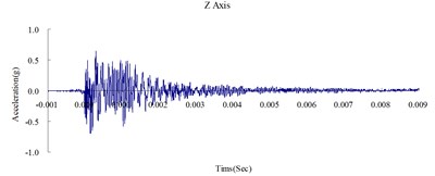
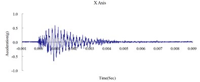
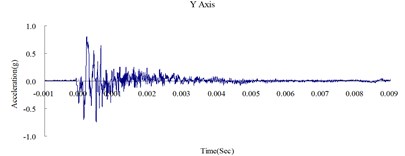
Fig. 4Time history of the surface acceleration at 500 cm from the blast source
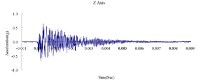
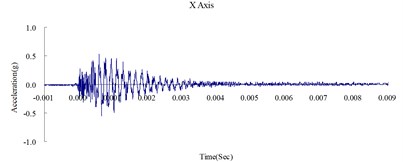
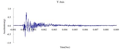
Fig. 5Time history of the surface acceleration at 650 cm from the blast source
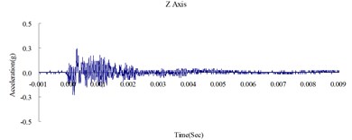
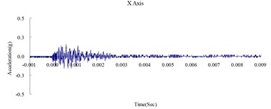
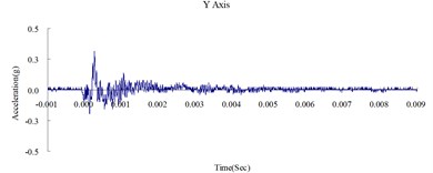
Fig. 6Time history of the surface acceleration at 350 cm from blast source (numerical analysis)
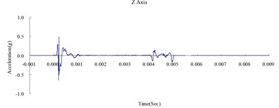
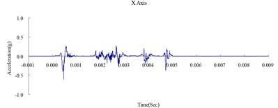
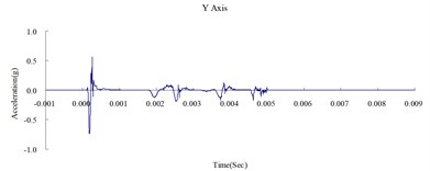
Fig. 7Time history of the surface acceleration at 500 cm from the blast source (numerical analysis)
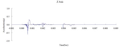
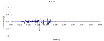
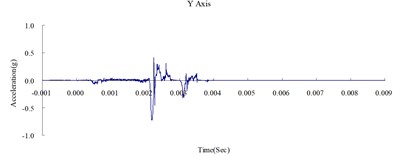
Fig. 8Time history of the surface acceleration at 650 cm from the blast source (numerical analysis)
4.2. Validation of the numerical model
Fig. 6, 7, and 8 show the acceleration time history obtained from the numerical analysis of the ground surface acceleration at 350, 500, and 650 cm from the blast source, respectively. The vertical ground surface acceleration was used to validate the results of the numerical analysis. The relative margin of error was calculated by subtracting the experimental results from the numerical analysis results, divided by the experimental reading, and multiplied by 100. The vertical ground surface acceleration relative margins of error at 350, 500, and 650 cm from the blast source were –8.11 %, –7.41 %, and –9.22 %, respectively. All margins of error were within 15 %. According to previous research [4], these results validate the reliability of the numerical analysis model and confirm that the MMALE algorithm can accurately analyze the propagation characteristics of shock waves from explosions.
4.3. Dynamic characteristics of the blast wave
An explosion is a phenomenon involving a rapid release of energy. The high temperatures and pressures quickly decompress the surrounding medium, resulting in shock waves. The blast wave affects the internal stability of materials. Structural designs must include improved anti-shock-wave protection measures to ensure safety. Ground surface vibrations caused by explosions are the result of energy transfer and conversion. The propagation of blast waves through the air is termed air-induced ground motion, whereas that through surface materials is referred to as a directly transmitted ground shock. An explosion produces a spherical shock wave that causes vibrations in the ground surface. Surface and underground explosions cause shock waves in the soil. Shallow underground explosions cause shock waves to form in both the air and soil. Drilling and blasting underground explosives cause shock waves directly in the soil and motion in the ground surface, both of which are affected by the distance from the explosion.
Fig. 9Time history of changes in shock wave pressure in a soil medium
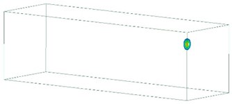
a) 100 μs
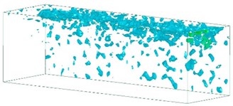
b) 2,000 μs
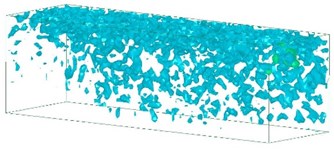
c) 4,000 μs
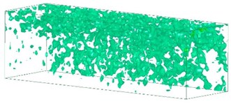
d) 6,000 μs
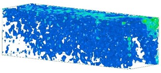
e) 8,000 μs
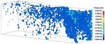
f) 10,000 μs
Fig. 9 shows the changes in shock wave pressure in a soil medium over time. The energy released during an explosion forms a dynamic pressure wave that produces a shock wave in air or soil. The blast transmits a stress wave through soil in the form of a compression wave. The blast pressure pushes outward as a sphere, but the shock wave energy decays within milliseconds. Explosions cause stress in the medium to propagate outward, forming a cavity at the center of the explosion. Surrounding the cavity, from innermost to outermost layers are the fracture, elastic-plastic, and elastic zones. In the propagation process, the shock wave first forms an elastic shock wave and then a plastic shock wave. Plastic shock waves are affected by unloading disturbances. The pressure and wave velocities decay continuously, and the impedance changes with the pressure. When the pressure wave reaches a free surface and is reflected in the form of a tensile wave, the resulting action of the expansion wave, pressure wave, and pressure of the explosive gases generates tensile waves and shear waves at the ground surface. The analysis results show that the shock waves near the blast source were fast and strong. These results correspond to the compression waves in the soil, which are key parameters influencing ground surface vibrations.
5. Conclusions
In this study, field tests were conducted and LS-DYNA was employed to examine the formation of high-stress shock waves during explosions and their characteristics and actions in the soil by exploring the dynamic reactions of the ground surface under identical energy conditions during an explosion. The results obtained on the propagation of shock waves in soil and the characteristics of the dynamic reactions at the ground surface may serve as a reference for future studies on planning and design of protective constructions. The results show that using the finite element method to simulate the dynamic characteristics of soil after an explosion provides accurate simulation results. Characteristics of the stress wave propagation were determined by examining the dynamic behavior of soil after being subjected to a blast. The largest and primary stress wave weakened with increasing distance from the blast point. The overall trend observed by numerical analysis matched the attenuation characteristics of the blast wave energy, indicating that the MMALE algorithm can accurately analyze the dynamic reactions of shock waves in soil. An understanding of the phenomena involved in the propagation of vibrational waves through the ground surface from the perspective of controlling vibrations caused by explosions is necessary for blast-resistant planning and design in construction projects.
References
-
Structures to Resist the Effects of Accidental Explosions. Technical Manual TM5-1300, US Army Engineers Waterways Experimental Station, Washington, DC, 1990.
-
Wang J. Simulation of Landmine Explosion Using LS-DYNA 3D Software: Benchmark Work of Simulation in Soil and Air. Aeronautical and Maritime Research Laboratory DSTO-TR-1168, 2001.
-
Wang Z. Q., Y. Lu. Numerical analysis on dynamic deformation mechanism of soils under blast loading. Soil Dynamics and Earthquake Engineering, Vol. 23, 2003, p. 705-714.
-
Kivity Y., Shafri D., Ben-Dor G., Sadot O., Anteby I. The blast wave resulting from an accidental explosion in an ammunition magazine. International Symposium on Military Aspects of Blast and Shock Conference, Canada, 2006.
-
Fundamental of Protection Design for Conventional Weapons. Technical Manual TM 5-855-1, US Army Engineers Waterways Experimental Station, Washington, DC, 1998.
-
Crandle F. J. Ground vibration due to blasting and its effect upon structures. Boston Society of Civil Engineering, Vol. 36, 1949, p. 222-245.
-
Koga Y., Matsuo O. Shaking table tests of embankments resting on liquefiable sandy ground. Soils and Found, Vol. 30, Issue 4, 1990, p. 162-174.
-
Pullen A. D., Ianucci L., Newman J. B., Perry S. H. Experimental Investigation of the dynamic loading of soil and the use of finite element simulation for analysis. International Conference – Structures Under Shock and Impact, 1989, p. 443-454.
-
Stamatopoulos C., Petridis P., Bassanou M., Allkja S., Loukatos N., Small A. Improvement of dynamic soil properties induced by preloading verified by a field test. Engineering Geology, Vol. 163, 2013, p. 101-112.
-
Dowding C. H. Blast Vibration Monitoring and Control. Prentice-Hall, Englewood Cliffs, NJ, 1985.
-
Ak H., Iphar M., Yavuz M., Konuk A. Evaluation of ground vibration effect of blasting operations in a magnesite mine. Soil Dynamics and Earthquake Engineering, Vol. 29, Issue 4, 2009, p. 669-676.
-
Wang I. T. Numerical analysis of the dynamic response of slope under the blasting vibration effect. International Journal of Computer and Electrical Engineering, Vol. 6, Issue 4, 2014, p. 351-357.
-
LS-DYNA Theoretical Manual. Livermore Software Technology Corporation, 1998.
-
LS-DYNA Keyword User’s Manual. Livermore Software Technology Corporation, 2009.
-
LS-DYNA Theory Manual. Livermore Software Technology Corporation, 2006.
-
Dobratz B. M. LLNL Explosive Handbook Properties of Chemical Explosives and Explosive Simulants. Lawrence Livemore National Laboratory, 1981.
-
Len S. Geomaterial Modeling with LS-DYNA. Livermore Software Technology Corporation, 2001.
About this article

This study was partially supported by the Ministry of Science and Technology, Taiwan, R.O.C. through Grant MOST 104-2221-E-145-004.
