Abstract
A reduction method for flexible elastic-plastic dynamic problems using component mode synthesis is presented. To obtain modal transformation matrix, the incremental governing equations of elastic-plastic problems are derived from nonlinear finite element theory and be simplified by using pseudo-force technique. A flexible elastic-plastic simply supported beam under impulsive load is examined with this method. The simulation results show that the proposed method is valid for elastic-plastic dynamic problem and has higher computation efficiency compared finite element method.
1. Introduction
The dynamic analysis of structures that experience plastic deformation has been a concerned topic for engineering applications. It is typically performed using finite element method (FEM). Since the plastic deformation is path dependent, the dynamic external loads must be applied onto structures incrementally during the analysis. The time step size should be small enough to ensure the accuracy and reliability of solution. If plastic deformation occurs during the time step, further iterations are required to obtain the pre-defined convergence at the current time step. Thus, the calculation of elastic-plastic dynamic response of structures has been marked by time-consuming. In order to mitigate this problem, reduced order models are gaining a lot of attention. Since any reduction in the computational effort of an iteration will be substantial when multiplied by the number of iterations in the solution of this problem.
The Component mode synthesis (CMS) is a modeling method to reduce the size of a dynamic problem by neglecting the higher modal frequencies of components without significantly degrading the accuracy of the solution. The pioneering works of CMS are proposed by Hurty [1] and Craig and Bampton [2]. Subsequently, the CMS is deeply studied and widely used for solving dynamic problems in linear system [3-5]. However, this method is based on modal technique, and be limited to linear system. As the great successful applications in linear system, the applications of nonlinear dynamic problems are active research fields currently [3].
The applications of CMS method for dynamic problems with local nonlinearities are summarized in [5]. The solutions of contact impact problem with CMS were first proposed by Wu and Haug [6], and more deep study are developed in [7, 8]. With pseudo-force technique to approximate the effect of nonlinearities during a dynamic simulation, the CMS was used to model dynamic problems with geometrical nonlinear [9] and with material nonlinear [10]. Recently, the applications of nonlinear normal modes to reduce nonlinear dynamic problem are gotten a lot of attention [11].
This work is focused on developing a reduction method for elastic-plastic dynamic response of general flexible structures. By considering plastic deformation induced by impulsive load, the coupling of pseudo-force technique and a fixed-interface CMS method is investigated. The incremental governing equations of elastic-plastic dynamic problem are derived from nonlinear finite element theory. Using pseudo-force technique, the plastic effects are addressed by applying a internal force placed on the right-hand side of the equations, which induces the incremental plastic deformation. And the left-hand side of the equations remains linear. Then, the governing equations can be transformed into modal coordinates with fixed-interface CMS directly. The modal frequencies and vectors of initial state of components are used throughout the entire analysis. Using the proposed method, there is only need to update internal force at each time step with iterative algorithm, and the computational benefits of the reduced order model are retained for iterations. The elastic-plastic dynamic responses of a flexible simply supported beam under impulsive load is simulated to demonstrate the validity, accuracy and efficiency of the proposed method by comparing to a FEM solution of full order model.
2. Formulations and solution method
The formulations of the proposed method are presented in this section, including the derivation of incremental governing equations of elastic-plastic dynamic problem, the procedure to coupling pseudo-force technique and fixed-interface CMS method and an implicit direct integration method for solving equations.
2.1. Incremental governing equations of elastic-plastic dynamic problem
Considering the small strain and deformation type of a motion of an elastic-plastic finite body, by use of nonlinear finite element theory, the dynamic equilibrium equations for the general elastic-plastic dynamic problem at time can be expressed as [12]:
where is the constant, symmetric, positive-definite mass matrix. is the resisting force of structure at time , depends on the displacement field. is the applied external force vector at time . , are the nodal acceleration vector and nodal displacement vector of system at time . In Eq. (1), other terms such as damping, can be included, but is not pertinent to the topic in this paper, so it is neglected.
In elastic-plastic problem the is given by:
where stands for the strain-displacement matrix, stands for the stress vector at time . Typically, the vector of is differentiable, so that:
Substituting Eq. (3) into Eq. (1) and defining the tangent stiffness matrix , then:
With the consideration of the unbalance force in previous time , the complete incremental governing equations of elastic-plastic dynamic problem can be derived by invoking the dynamic equilibrium equations of Eq. (1) at time . The result takes the form:
2.2. Pseudo-force technique for elastic-plastic dynamic problem
The is equal to the incremental resisting force, that is expressed as:
In plastic theory, the strain increment can be partitioned into elastic strain increment and plastic strain increment , and the elastic strain increment is compliance with Hooke’s law. Thus, the stress increment can be written as:
Substituting Eq. (7) into Eq. (6), then:
where is the elastic stiffness matrix of structure, is an internal force induces the plastic deformation increment and be defined as:
Generally, is calculated in terms of appropriate plastic law with iterative algorithm. Substituting Eqs. (8)-(9) into Eq. (7), the incremental governing equations are rewritten as:
Observing Eq. (10), the left-hand side of governing equations remains linear, nonlinear effects are approximated by applying an internal force placed on the right-hand side of equations.
2.3. Substructuring and fixed-interface CMS
Fixed-interface CMS approach is one of the most commonly used CMS method [2]. Where the linear equations of motion are reduced using a truncated set of fixed-interface modes, and constraint modes. By dividing the structure into several substructures artificially, the un-damped incremental governing equations of a substructure are written in the partitioned form:
where the subscript indicates the interior DOFs (degrees of freedom), the subscript indicates the boundary DOFs. The superscript denotes the serial number of the substructure divided artificially, and is the force applied on boundary of the substructure.
The Fixed-interface CMS uses two sets of substructure modes to generate transformation matrix, namely, the fixed-interface normal modes and constrain modes . Fixed-interface normal modes are defined as the free vibration modes of a restrained substructure, and are obtained by solving an eigenvalue problem. The constraint modes are the static deflections of substructure. This are calculated by applying successive unit displacements at each boundary degrees of freedoms, all other boundary degrees of freedoms being totally constrained. The overall transformation matrix of a substructure will take the form:
where is the first order fixed-interface normal modes.
With the consideration of displacement compatibility and force equilibrium of the interface DOFs at the conjunction region of substructures, and eliminating repeated interface DOFs, an assembled model form all substructures is obtained. The Eq. (12) is converted into the reduced set of coordinates:
where is the transformation matrix of structure assembled from substructures, , .
2.4. Solution method
In this paper, an implicit direct integration method (Newmark algorithm) is employed to solve Eq. (13). With the help of Newmark method, the corresponding effective static equilibrium equations of Eq. (13) can be expressed as follows:
The Eq. (14) is solved with iterative algorithm. The effective stiffness matrix of structure is only decomposed once during the entire analysis, which is more computationally effective compared with FEM. In current time step, the initial value of internal force can be assumed to be equal to the convergent value of previous time step, and be calculated by Eq. (8) or Eq. (9) according to an appropriate plastic law in the subsequent iteration. The iterations of are usually converged rapidly.
3. Numerical example
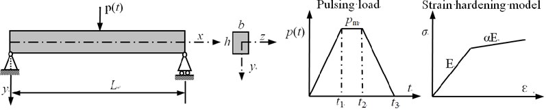
Considering a flexible elastic-plastic simply supported beam under a concentrated load as depicted in Fig. 1. The length is 3.0 m, width is 0.15 m, height is 0.075 m; Young’s modulus is 2.0e11 Pa, Poisson’s ratio is 0.27, density is 7800 Kg/m3, yield stress is 235 MPa. The material is assumed to be isotropic bilinear strain hardening model with an tangent modulus of , and obey the von Mises criterion. The values of parameters used in are taken as: 0.005 s, 0.007 s, 0.012 s, . Where is the static collapse load defined as the concentrated load causing a plastic hinge to occur at the midpoint of the beam.
Fig. 1Geometric, material and external load properties of example
In this paper, the proposed method is adopted to calculate the dynamic response of the beam to demonstrated the validity and efficiency of the presented method. During the simulation no damping is assumed for the beam, and the time increment equals 1.0e-5 sec. In addition, the beam is meshed using 100 beam elements, and the finite element model is divided into 10 substructures uniformly, each substructure retains the lowest fixed-interface normal modes.
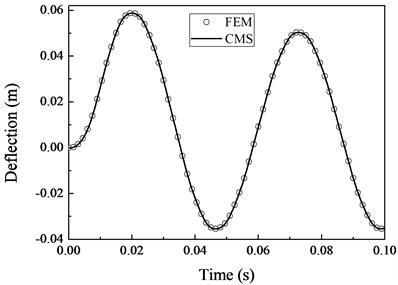
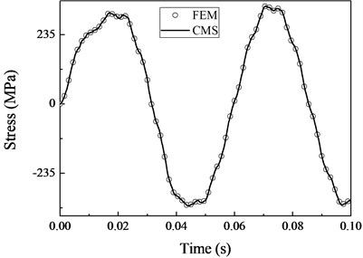
Fig. 2 shows the deflection and normal stress of bottom surface at the center of beam as a result of the applied loading with 0.25. They all agree well with the solution obtained with FEM.
Fig. 2Comparison of the deflection and normal stress obtained with CMS and FEM
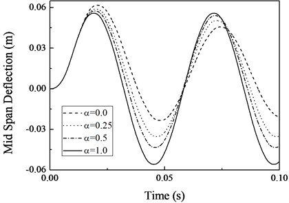
The displacement response of the midpoint of the beam for different are given in Fig. 3. It is observed that the rate of the hardening model increases the first peak of deflection decreases. This is reasonable, when 0.0, the material is ideal plastic which has no hardening effect, the first peak of deflection is biggest. The plastic deformation can soften the beam. This leads to that the effective period of vibration decrease with the increase of the rate of hardening model [13]. When the load is removed, the beam oscillates in a vicinity of the equilibrium position, which has an offset form 0 displacement position due to the plastic deformation.
Fig. 3Effect of strain-hardening material on response of the beam
The CPU time of the simulation is shown in Table l, we can make a clear observation that the CMS has higher efficiency than FEM. For this example, the time cost of CMS is decreased 36 percent compared with the time cost of FEM.
Table 1Time cost of simulation
Method | Time cost (s) |
FEM | 188.72 |
CMS | 120.95 |
4. Conclusions
A numerical method using a fixed-interface CMS to analyze the elastic-plastic dynamic response of structures has been proposed.
The method is illustrated by the analysis of dynamic elastic-plastic response of simply supported beams. The material of beam is assumed to be bilinear isotropic hardening model. The load applied to beam is impulsive load. Numerical results have a good agreement with those obtained by FEM. The numerical results demonstrate that the proposed method has higher computation efficiency compared with FEM with the same accuracy.
References
-
Hurty W. C. Dynamic analysis of structural systems using component modes. AIAA Journal, Vol. 3, Issue 4, 1965, p. 678-685.
-
Bampton M. C. C., Craig R. R. Jr. Coupling of substructures for dynamic analyses. AIAA Journal, Vol. 6, Issue 7, 1968, p. 1313-1319.
-
Klerk D. D., Rixen D., Voormeeren S. General framework for dynamic substructuring: history, review and classification of techniques. AIAA Journal, Vol. 46, Issue 5, 2008, p. 1169-1181.
-
Craig J. R. R. Substructure methods in vibration. Journal of Vibration and Acoustics, Vol. 117, Issue B, 1995, p. 207-213.
-
Seshu P. Substructuring and component mode synthesis. Shock and Vibration, Vol. 4, Issue 3, 1997, p. 199-210.
-
Wu S. C., Haug E. J. A substructure technique for dynamics of flexible mechanical systems with contact-impact. Journal of Mechanical Design, Vol. 112, Issue 3, 1990, p. 390-398.
-
Guo A., Batzer S. Substructure analysis of a flexible system contact-impact event. Journal of Vibration and Acoustics, Vol. 126, Issue 1, 2004, p. 126-131.
-
Shen Y., Yin X. Dynamic substructure analysis of stress waves generated by impacts on non-uniform rod structures. Mechanism and Machine Theory, Vol. 74, 2014, p. 154-172.
-
Kuether R. J., Allen M. S. Craig-Bampton substructuring for geometrically nonlinear subcomponents. Proceedings of the 32nd IMAC, A Conference and Expositionon Structural Dynamics, Dynamics of Coupled Structures, Vol. 1, 2014, p. 167-178.
-
Bond J., Khraishi T. Transient non-linear simulation with component mode synthesis. International Journal of Mechanics and Materials in Design, Vol. 5, Issue, 4, 2009, p. 365-380.
-
Apiwattanalunggarn P., Shaw S. W., Pierre C. Component mode synthesis using nonlinear normal modes. Nonlinear Dynamics, Vol. 41, Issue 1, 2005, p. 17-46.
-
Zienkiewicz O. C., Taylor R. L., Fox David The Finite Element Method for Solid and Structural Mechanics. Sixth Edition, Elsevier Ltd., Amsterdam, 2006.
-
Liu S. C., Lin T. H. Elastic-Plastic dynamic analysis of structures using known elastic solutions. Earthquake Engineering and Structural Dynamics, Vol. 7, 1979, p. 147 159.
About this article

This research has been supported by Postdoctoral Fund of JiangSu (1402007B), the support is gratefully acknowledged.
