Abstract
Multiple modules-offshore platform is a typical dynamic network with flexible-rigid-fluid coupling. The determination of the motions of this system in response to environmental forces and structure control mechanisms is a complex procedure, which may include system nonlinearities and position-dependent environmental loads, as well as any motion control mechanisms. For a systematic parametric study, given the large number of possible combinations of environmental conditions, a time domain analysis would be prohibitively time-consuming. However, frequency domain evaluation of AQWA can provide a simple and fast tool to fulfill this requirement.
1. Introduction
Multiple modules-offshore mobile platforms can be a sea comprehensive supply base with refueling, aircraft movements, logistics and other functions. More importantly, it can be used to protect national maritime rights. Therefore, it set off research upsurge of very large floating structures in international ocean engineering. Scholars from all over the world have spread a lot of theories of very large floating ocean structure [1-3]. Japanese scholars study pontoon offshore platforms and test the feasibility of floating platform [4-7]. Compared with Japan, the United States put forward the semi-submersible offshore base and related research [8-9]. Xu Daolin [10] set up a rigid-soft coupling network system. But it is only analyzed the one-dimensional network mechanics system composed of single direction connection. This paper will be based on the AQWA to analyze two-dimensional floating network system. This work provides a new methodology and an application example in the study for network structural dynamics, including very large scale floating structures.
2. Theory and models
2.1. Response spectral density
In a linear dynamic system consisting of structures, the equation of motion in the frequency domain is written as:
where , and are the 6×6 mass, damping, and stiffness matrices respectively, is the 6×1 motion response, and is the 6×1 external force, at frequency .
In Eq. (1), is called the impedance matrix, while the receptance matrix is defined as:
The motion response in complex values can then be expressed as:
In multi-directional waves, denoting the ordinate of the th directional wave spectrum in direction at frequency as , the 6×6 general transform function due to the first order wave ex-citation is defined as:
where the superscripts ‘’ and indicate the conjugate transpose and non-conjugate transpose of a matrix respectively, and is the number of wave directions. The diagonal terms of the real part of the general transform function matrix are the motion response spectral densities, i.e.
Wave excitation force spectral density is:
2.2. Geometry and environmental parameters
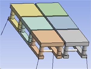
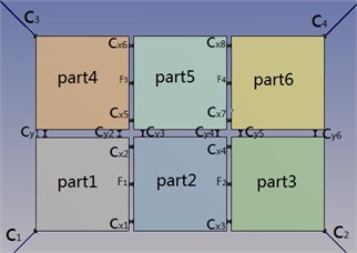
Multiple modules-offshore mobile platform is composed of six same models through cable and Fender, as shown in Fig. 1. Denoting as the mooring line stiffness and as its initial unstretched length, and , as the attachment points on the two structures (in the fixed reference axes, where one structure may be a fixed location, for instance an anchor point), the tension on the mooring line is defined as:
where the stretched length of the cable is .
Fig. 1Multiple modules-offshore mobile platform
The magnitude of the fender axis-directional compression force is defined as a polynomial function of the compression, as:
where ( 1, 5) are the coefficients of the polynomial function and .
The main characteristic parameters of a single module is shown in Table 1. This paper adopts a once-in-a-century extreme condition in South China Sea, as shown in Table 2.
Table 1The main characteristic parameters of a single module
Parts | Parameters size |
Deck (length width height) (m) | 100×100×14 |
Pillar (high diameter) (m) | 35×17 |
Buoy (length width height) (m) | 100×18×10 |
Beam pillar (diameter) (m) | 8 |
Other parameters | Normal waterline 25 m |
Displacement46440e3 m3 | |
7.91e10 (kg∙m2) | |
6.49e10 (kg∙m2) | |
9.35e10(kg∙m2) | |
Center of gravity from the waterline 5.0 m |
Table 2Environmental loading conditions of South China Sea
Parameters | The numerical | |
The waves | Significant wave height /m | 13.5 |
Peak period/s | 15.5 | |
Angle / (°) | 180 or 225 |
3. Frequency domain analysis
Due to large amounts of data, the paper selectedpart1 constrained by the anchor and part5 located in the central position of the chain structure to analyze. There is little literature research double row floating structure system, so this paper focuses on the lateral cables -, study how the two floating bodiescoupling in the lateral.
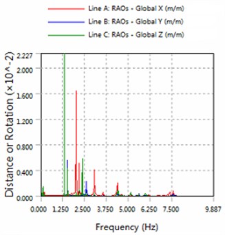
Fig. 2The amplitude of horizontal swing and the heave for part1
a) 180 degree angle for wave
b) 225 degree angle for wave
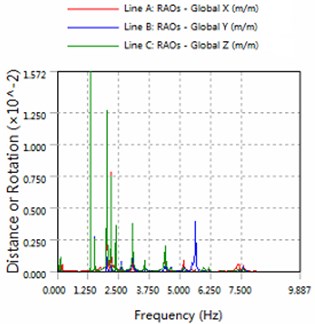
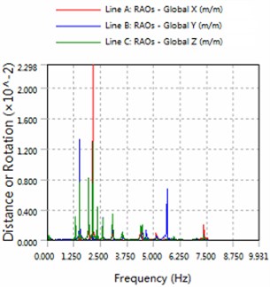
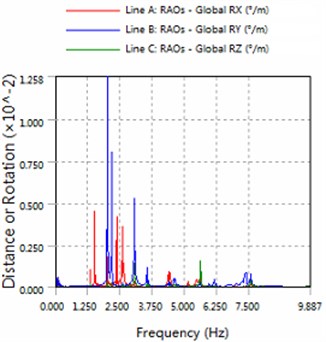
By analyzing Figs. 1 to 7, can be obtained summary:
1) In the same sea conditions, part5 motion response amplitude is greater than part1. Because part1 constraints by the anchor, so it is realistic.
2) The platform is sensitive to the wave frequency of 1.25 Hz-7.5 Hz range. In engineering application, we prevent the frequency of this region to damage multiple modules-offshore mobile platform.
3) The magnitude of floating structure and cable and fender at wave of 180 degree angle are less than the magnitude at wave of 225 degrees. Therefore, in engineering applications, modules-offshore mobile platform should give more consideration to against the waves to arrange.
Fig. 3The amplitude of roll, pitch and the yaw for part1
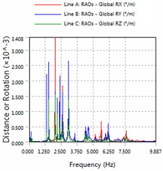
a) 180 degree angle for wave
b) 225 degree angle for wave
Fig. 4The amplitude of horizontal swing and the heave for part5
a) 180 degree angle for wave
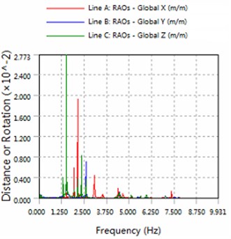
b) 225 degree angle for wave
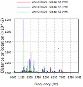
Fig. 5The amplitude of roll, pitch and the yaw for part5
a) 180 degree angle for wave
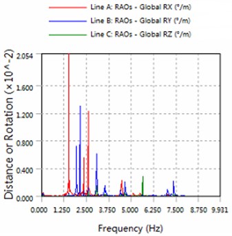
b) 225 degree angle for wave
Fig. 6The amplitude of cable force
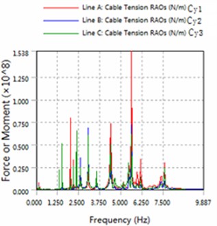
a) 180 degree angle for wave
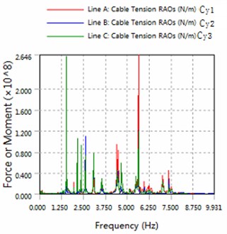
b) 225 degree angle for wave
Fig. 7The amplitude of fender force
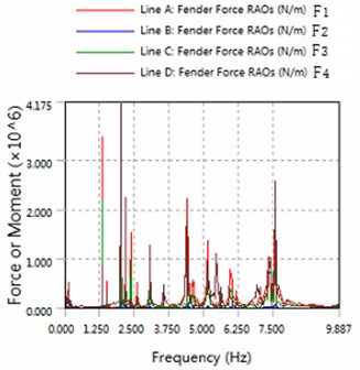
a) 180 degree angle for wave
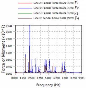
b) 225 degree angle for wave
4. Conclusions
At present few literature study multi-row and multiple modules-offshore platform, this paper use AQWA for frequency domain analysis of this platform. And preliminary results are obtained. Frequency domain analysis can get exact solution quickly and can provide the reference that whether designers decided to improve the system. This work provides a new methodology and an application example in the study for network structural dynamics, including very large scale floating structures.
References
-
Ohmatsu S. Overview: research on wave loading and responses of VLFS. Marine Structures, Vol. 18, Issue 2, 2005, p. 149-168.
-
Wang C. M., Tay Z. Y. Very large floating structures: applications, research and development. Procedia Engineering, Vol. 14, 2011, p. 62-72.
-
Fujikubo M. Structural analysis for the design of VLFS. Marine Structures, Vol. 18, Issue 2, 2005, p. 201-226.
-
Yoshida K. Developments and researches on VLFS in Japan. Proceedings of the Second International Workshop on Very Large Floating Structures, Hayama, Japan, 1996.
-
Kyozuka Y., Kato S., Nakagawa H. A numerical study on environmental impact assessment of mega-float of Japan. Marine Structures, Vol. 14, Issue 1, 2001, p. 147-161.
-
Suzuki H. Overview of mega-float: concept, design criteria, analysis, and design. Marine Structures, Vol. 18, Issue 2, 2005, p. 111-132.
-
Sueoka H., Sato C. Phase H research of mega-float. Proceedings of the Tenth International of Shore and Polar Engineering Conference, Seattle, USA, 2000.
-
Bhattacharya B., Basu R., Ma K. Developing target reliability for novel structures: the case of the mobile off shore base. Marine Structures, Vol. 14, Issue 1-2, 2001, p. 37-58.
-
Remmers G., Zueck R., Palo P., et al. Mobile off shore base. Proceedings of the Eighth International Oshore and Polar Engineering Conference, Montreal, Canada, 1998.
-
Xu Daolin, Lu Chao, Zhang Haicheng Dynamic modeling and nonlinear characteristics of floating airport. Chinese Journal of Theoretical and Applied Mechanics, 2015.
About this article

This work is supported by the National Natural Science Foundation of China (11572356, 111272361), Doctoral Program Foundation of Ministry of Education of China (20130171110039), Guangdong Province Natural Science Foundation (1414050000412, S2013010013802), the Guangdong Province Science and Technology Program (2012A030200011), and Fundamental Research Funds for the Central Universities (15lgzd01).
