Abstract
In this paper a forced oscillations of two-mass system, induced by unbalance vibration exciter driven by asynchronous AC motor of limited power, are considered. The mathematical model of the system is obtained by taking into account static characteristic of the motor. Oscillations of the system in resonances zones are analyzed, and relations between power input and dissipated power are estimated depending on the system parameters.
1. Introduction
One of the problems of creating high-performance vibrating machines is to ensure stability of required oscillation regimes while reducing power consumption for their maintenance. In present time the most of vibrating machines are single-mass systems, which oscillation are excited in after-resonance regimes, which is due to its stability, however they have low efficiency of use a disturbing force [1-3]. One way to solve this problem is in application of multimass, for example, two-mass dynamic scheme of vibrating machines. Introduction of additional mass improves dynamic equilibrium of the machine, which leads to improving its vibration isolation and enables its operation at the resonant or near-resonant mode. At the same time, as it is known [2, 4-6], an oscillating system can significantly effect on an energy source, which depends on the ratio of input and dissipated energies, and can lead to “sticking” at a certain frequency or abrupt change in frequency and in oscillation amplitude - the so-called effect of Sommerfeld [1, 2, 4].
These effects may limit operational capabilities of vibrating machines and require a special study in every case. Questions of interaction of oscillatory systems with non-ideal source of energy has been widely discussed in many works [2, 3-6], which are mainly focused on the analysis of systems having single "basic" degree of freedom. General methods for research nonlinear systems with many degrees of freedom are also given [2, 4, 7]. In the literature devoted to the dynamics of vibrating technological machines, analysis of multimass dynamic schemes is carried out without taking into account interaction with an energy source [3, 8].
In this paper, we consider a model of vibrating machine as a system of two solids connected with each other and with fixed base by viscoelastic dampers. Each of the masses can perform only unidirectional oscillations which are excited by rotation of an unbalanced rotor of asynchronous motor of limited power. Dynamic properties of the motor are taken into account as static characteristics determined by Kloss formula [8]. Interaction of the oscillatory system with the motor in the resonance region is analyzed with evaluation of input and dissipated power relationship depending on the system parameters.
2. Mathematical model
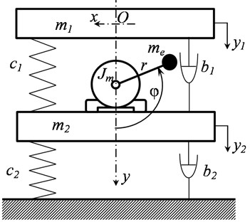
Dynamic scheme of vibrating machine is shown in Fig. 1. It consists of working body with operational load on it which are presented as a single rigid body of mass , and a platform with rigidly attached unbalance vibration exciter driven by asynchronous motor with cage rotor, which are modelled by a single rigid body of mass . The working body and the platform are connected to each other by viscoelastic damper with linear characteristics of stiffness and viscous friction , the platform is also connected to a fixed base by viscoelastic damper with linear characteristics of stiffness and viscous friction . Working body and platform can move only along the vertical direction. The exciter has unbalanced mass and eccentricity . Gravity is not taken into consideration.
Motion of the system is considered relative to a fixed coordinate system , the beginning of which coincides with the center of mass of the working body. Displacements of working body and platform are determined by displacements of its centers of masses and , respectively, relative to their positions of static equilibrium. Angular position of debalance is determined by angle measured from its lower vertical position.
Fig. 1Dynamic scheme of vibrating machine
According to the purposes of the study we consider steady or close to steady oscillations regimes, that is when the motor angular speed changes quite slowly, so to describe driving moment we use static characteristics of the motor determined by Kloss formula [4, 8]. Friction in rotor supports is considered as a constant value .
Then motion of the system is described by the following system of equations:
where , – maximum moment of the motor, – slip corresponding to this moment, – idle angular speed of the motor.
Let’s introduce the dimensionless variables for time and displacements , and choose scale factors for time and displacements so that , , where and . Then Eq. (1) could be represented in dimensionless form:
where:
() and () in Eq. (2) are the first and the second derivative with respect to dimensionless time .
3. Solution method
One of the main objectives of the present study is to investigate the interaction of the oscillating system with the motor in the zones of “main” resonances. According to this let us turn to the analysis of particular solutions of the system Eq. (2) which correspond to single-frequency oscillations. Assuming that changes little over the maximum period of free oscillations of the system, the viscous resistance is low, the natural frequencies (1, 2) are simple roots of the characteristic equation for a system consisting of left sides of the first two equations of Eq. (2), we use the method of Bogolyubov of perturbation theory [2, 4, 7], to obtain an approximate solution of Eq. (2). Following this method we represent the solution through its main coordinates and : , , where, (, 1, 2) – coefficients of form functions corresponding to eigenfrequencies .
For each of these coordinates we seek the solution in form , taking into account , , and , , are slowly varying in time with respect to the main period of oscillations.
Let’s consider the solution in the first approximation. Here we note that fluctuations of coordinate are small in comparison with when considering motion of the system near the frequency , so we can neglect when receiving solution in first approximation. Similar to this, fluctuations of coordinate are small in comparison with when considering motion of the system near the frequency .
Thus, we obtain the following expression for determining the amplitude and frequency of vibrations:
– near the resonance :
where ;
– near the resonance :
where .
4. Results analysis
From Eqs. (4) and (6) one can see that oscillation frequency depends on characteristics of the motor and oscillation amplitude , and oscillation can only occur with the frequency satisfying these equations. A clear understanding of the possible modes of oscillation provides a graphical representation of Eqs. (4) and (6) given in Fig. 2, where is the moment of forces of resistance to oscillatory motion, determined as:. Curves , , , represent characteristics of motors having different power, numbered in accordance with power increase. Moreover characteristics can be considered as adjusting characteristics of the same engine with natural characteristic in the implementation of so-called vector control, e.g. at simultaneous proportional change in frequency and amplitude of the power supply so that maintaining constant the ratio . Frequency of forced vibration corresponding to each of the motors is determined by points of intersection of their characteristics with functions . For example each of characteristics and intersect curves at only one point and respectively. Therefore there is only one possible oscillation mode for each motor with the frequency or respectively, and the more power of motor the higher oscillation frequency. Different situation occur when we use motor with characteristic , which intersects at five points , ,…, . Note that points , , correspond to stable oscillation modes and points and correspond to unstable modes.
Fig. 2Relations of driving moments and moments of forces of resistance to oscillatory motion
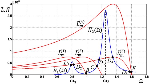
It is also interesting to note that although the nominal capacity of this engine is more than the first two, however, after it starts the system is unable to overcome first resonance, and come to steady mode of oscillation corresponding to point with frequency which is less than or . Considering and as adjusting characteristics for latter motor it is evident that we can overcome first resonance by appropriate control the motor characteristics at starting mode. However the control system is unable to adjust system to after-resonance oscillation mode, that is when oscillation frequency is greater than , and we should apply the motor with higher power, e.g. the motor with the characteristic . For this motor there is only one possible oscillation mode determined by point of intersection of curves and corresponding to after-resonance oscillation mode with frequency .
Increase in motor power usually leads to increase in its mass, size and cost of the entire system. At the same time, necessity of its increase is usually due to the possibility of overcoming the resonance regions where there is the greatest power dissipation because of substantial increase in oscillation amplitude. Therefore it seems appropriate to consider reducing the amount of energy dissipated in the resonance region, which is most determined by dissipative terms in Eq. (2). For this purpose consider behavior of function at . From Eq. (4) taking into account Eq. (3) we obtain:
One can see that resistance moment is inversely proportional to and , that is an increase in any of these parameters will result in a monotonic decrease in the resistance moment. The change in has more significant impact on than .
Similarly, considering function at , from Eq. (6) taking into account Eq. (5) we obtain:
Comparing Eqs. (7) and (8) we can say that depending on the parameters and behaves similarly to . Note that although increase in damping leads to the desired effect of reducing the resistance moment, it is not allowed to be increased indefinitely, and any other restrictions on the amount of damping, e.g. due to structural and technological parameters of the machine, should also be taken into account.
5. Conclusion
Presented here model of vibrating machine and analysis of its dynamics showed that for operation of two-mass vibration machine at after-resonant mode we need to apply more powerful motor than it’s needed to operate at pre-resonant or inter-resonance modes. The results and solutions could be the basis for further study of dynamics of two-mass systems with limited power of drive to determine rational values of their parameters and choice of operating modes.
References
-
Astashev V. K., Kolovsky M. Z., Babitsky V. I. Dynamics and Control of Machines. Springer-Verlag, Berlin Heidelberg, 2000.
-
Blekhman I. I. Vibrational Mechanics. Nonlinear Dynamic Effects, General Approach, Applications. World Scientific Publishing Co., Singapore, 2000.
-
Vibration in the Technique: Handbook. In 6 Vols. V.4. Vibration Processes and Machines. Mechanical Engineering, Moscow, 1981, (in Russian).
-
Kononenko V. Oscillatory Systems with Limited Excitation. Nauka, Moscow, 1964, (in Russian).
-
Guskov A. M., Panovko G. Y. A. Nonlinear effects at vibration of linear mechanical systems with centrifugal exciter of limited power. Engineering Journal: Science and Innovation, Vol. 6, Issue 6, 2012.
-
Niselovskaya E., Panovko G., Shokhin A. Oscillations of the mechanical system generated by an unbalanced rotor asynchronous electric motor. Journal of Machinery Manufacture and Reliability, Vol. 6, 2013, p. 17-23, (in Russian).
-
Nayfeh A. H. Perturbation Methods. Wiley, New York, 2000.
-
Kolovsky M. Z. Dynamics of Machines. Mashinostroenie, Leningrad, 1989.
About this article

The reported study was funded by RFBR according to the research project No. 15-08-06961a.
