Abstract
The expression of field transfer matrix of a ship propulsion shafting is deduced based on the modified Timoshenko beam theory using the transfer matrix method. Moreover, the power flow of each bearing of the propulsion shafting is carried out numerically. The Pareto optimal solution set is obtained by selecting the aft stern bearing stiffness, front stern bearing stiffness, thrust bearing stiffness and the bearing spacing length as the optimization design variables and selecting the sum of the power flow of each bearing of the propulsion shafting as the optimization objectives. Then, the Pareto optimal solution set is sorted by the TOPSIS method and MADM approach. The analysis results show that it is feasible and effective to avoid the blindness of selecting optimization results by optimizing the propulsion shafting multi-objectives based on the TOPSIS method and MADM approach.
1. Introduction
The propulsion shafting vibration caused by unsymmetrical propeller thrust is the main mechanical noise of underwater vehicles, which seriously affects the ship's acoustic stealth performance. Therefore, the optimization design of ship propulsion shafting is of great significance to improve the operational performance of underwater vehicles. As to ship propulsion shafting, the changes of bearing stiffness and the bearing spacing length have a significant impact on the vibration and the transfer characteristics of shafting.
Previously, Wang Bin [1] and Zhou Chunliang [2] studied the influence of bearing stiffness and the bearing spacing length on ship shafting vibration characteristics. However, to reduce the propulsion shafting vibration transmission, it is essential for us to consider comprehensively the aft stern bearing stiffness, front stern bearing stiffness, thrust bearing stiffness and the spacing length of each bearing, which involves the multi-variable and multi-objective optimization design of ship propulsion shafting and the selection problem of the Pareto optimal solution.
In this paper, a certain type of ship propulsion shafting is simplified to mass-point elements, elastic supporting elements and beam elements with the distributed parameters. The expression of field transfer matrix of each beam element which presents the relationship between the left side state vector of the beam and the right side state vector of the beam is deduced through the differential expression between internal forces and displacements of beam elements based on the modified Timoshenko beam theory. Then, the expressions of point transfer matrix of mass-point elements and elastic supporting elements are obtained according to the force and displacement conditions on either side of the point. After that, the Pareto optimal solution set is obtained by selecting the aft stern bearing stiffness, front stern bearing stiffness, thrust bearing stiffness and the bearing spacing length as the optimization design variables and selecting the sum of the power flow of each bearing of the propulsion shafting as the optimization objectives based on the multi-objective optimization algorithm (NSGA-II). And the Pareto optimal solution set is sorted by the TOPSIS method [3] and MADM approach [4].
2. Calculation model and principle
In this paper, the calculation model is shown in Fig. 1. The structural parameters of the propulsion shafting shown in Fig. 1 are listed in Table 1. The propulsion shafting is composed of the aft stern bearing, the front stern bearing, the thrust bearing, stern shaft and thrust shaft. The shaft is simplified to the four-span continuous beam, and it is divided into four elements, the corresponding node number is 0, 1, 2, 3, 4. Also the propeller is simplified to mass-point element, and the bearings are simplified to spring supports. The propulsion shafting is mass distribution, whose cross-section is hollow circular, as well as the bending stiffness is EI, the mass per unit length is m, and the cross-sectional area is A.
Fig. 1Simplified model of propulsion shafting structure
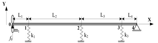
Table 1Parameters of propulsion shafting structure
Parameter | Unit | Value | Parameter | Unit | Value |
m | 0.8 | kg | 2200 | ||
m | 8.2 | N/m | 1.5e8 | ||
m | 4.2 | N/m | 5e7 | ||
m | 1.2 | N/m | 1.6e8 | ||
Outer radius | m | 0.09 | Inner radius | m | 0.04 |
The relational expression between the left side state vector of the shaft and the right side state vector of the shaft is established according to the corresponding boundary conditions when the propeller is exerted by a vertical harmonic force .
which is 4×4 square matrix is the field transfer matrix between the left side state vector of the shaft and the right side state vector of the shaft, as follows:
where is the point transfer matrix of mass-point elements and elastic supporting elements, and is the field transfer matrix of beam elements.
It is more accurate to solve the field transfer matrix of beam elements by Timoshenko beam theory than the Bernoulli-Euler beam theory, but the former also ignores the effect of the moment of inertia caused by the shear deformation of the beam bending vibration. Chen Rong has taken into account the impact of inertia and modified the Timoshenko beam bending vibration equation based on Timoshenko beam theory.
According to the free bending vibration equation of the modified Timoshenko beam [5]:
where is the effective shear coefficient.
The field transfer matrix of the beam element can be obtained by Eq. (3):
where , , , , , , , , , , , , .
The expressions of point transfer matrix of mass-point elements and elastic supporting elements are gained according to the force and displacement conditions of the connected node between the beam element and the beam element.
The boundary conditions on both sides of the shafting shown in Fig. 1 are as follows:
The left side is a free boundary: shear and bending moment is respectively zero:
The right side is simply supported: displacement and bending moment is zero:
The formula (5) and (6) into equation (1) can be obtained:
The left side of the shaft state vector can be obtained by solving equation (7):
The solution of the force and displacement response of the propulsion shafting bearing is carried out by substituting equation (8) to equation (1) and in accordance with the point transfer matrix and the field transfer matrix .
Thus, the transmitted power flow at path in Fig. 1 is carried out:
where and are the transmitted force at path and the transmitted velocity response at path respectively. The symbol “” represents the complex conjugate.
3. Parameters optimization of propulsion shafting
3.1. Parameters optimization model
The parameters optimization model of propulsion shafting can be expressed as the general form of multiple-objective optimization:
where, is the objective function, the meaning of the expression (11) is: the design variables is solved to minimized each objective function in under the inequality constraints and equality constraints .
3.1.1. Optimization variables
It is more difficult to change the installation position of the aft stern bearing and thrust bearing, while changing the front stern bearing is achievable. Therefore, it is feasible to select the aft stern bearing stiffness , front stern bearing stiffness , thrust bearing stiffness and the bearing spacing length between the front stern bearing and the thrust bearing as the optimization design variables, as follows:
The range of the optimization design variables is shown in Table 2.
Table 2Variables range
Parameter | Variables range | Parameter | Variables range |
[8.0e7, 2.0e8] | [1.5e8, 3.0e8] | ||
[5.0e7, 8.0e7] | [7.5, 9.0] |
3.1.2. Objective function
The minimum of the sum of the transmitted power flow of each bearing within 0-150 Hz frequency band is objective function, as follows:
where, , , represent the transmitted power flow of the aft stern bearing, the front stern bearing and the thrust bearing respectively.
3.1.3. Constraint function
Since the position of the thrust bearing and the aft stern bearing can not be changed, so the equality constraint condition is:
3.2. Optimization calculation
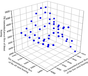
In this paper, the optimization algorithm is NSGA-II, the population size is 12, the maximum genetic evolution generation is 20, the crossover probability is 0.9. A total of 59 Pareto optimal solutions is obtained after optimization calculation and the three-dimensional distribution of the Pareto optimal solution set is shown in Fig. 3. As can be seen from the figure, the changing of the transmitted power flow of thrust bearing is the greatest, while the aft stern bearing is the minimal within the range of the optimization design variables.
Fig. 2The set of Pareto optimal solution
4. Multiple attribute decision making
The multi-objective optimization is not just an optimization problem, but also a decision problem. As can be seen from the Fig. 2, the Pareto optimal solution is not unique and the policymakers have to choose a reasonable Pareto solution from a series of optimization parameters and results.
The attribute decision matrix of the Pareto optimal solution set is established based on the TOPSIS. The weights of the optimal solution attribute matrix is calculated and the sorting scheme of the Pareto optimal solution is given by the information entropy objective empowerment method.
The multi-objective optimization of the propulsion Shafting can be described as multi-attribute decision making with four schemes and three attributes. Therefore, the decision matrix size of the Pareto optimal solution is 59×3.
The weights of three objective attributes is given in Table 3 by the information entropy objective empowerment method. As can be seen from the table, the attribute of the thrust bearing is the largest, the second is the front stern bearing, and the aft stern bearing is minimum, which is consistent with the results in Fig. 2.
The top five schemes which are shown in Table 4 is received based on the similarity by sorting the attribute decision matrix of the Pareto optimal solution set.
Table 3The weights of objective attribute
Objective attribute | |||
Weight | 0.0374 | 0.2937 | 0.6689 |
Table 4TOPSIS sorting result
Similarity | Order | |||||||
1.13e8 | 7.72e7 | 2.58e8 | 8.48 | 5334 | 4162 | 3514 | 0.9691 | 1 |
1.10e8 | 7.72e7 | 2.60e8 | 8.48 | 5356 | 4185 | 3503 | 0.9670 | 2 |
1.10e8 | 7.72e7 | 2.56e8 | 8.46 | 5359 | 4191 | 3490 | 0.9670 | 3 |
1.10e8 | 7.62e7 | 2.56e8 | 8.31 | 5324 | 4205 | 3500 | 0.9622 | 4 |
1.10e8 | 7.85e7 | 2.56e8 | 8.62 | 5322 | 4188 | 3546 | 0.9458 | 5 |
The first sorting solution is the optimal solution. The figures of the transmitted power flow curves of each bearing shown in Fig. 4 are obtained and compared with the previous scheme of propulsion shafting. As can be seen from the figure, compared with the previous scheme, the multi-objective optimization of the shafting has a little impact in 0-35 Hz low frequency band, but the transmitted power flow is significantly reduced after the 35 Hz frequency, especially the front stern bearing and the thrust bearing.
Fig. 3Power flow curves of different transmission bearings before and after optimization
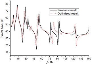
a) The transmitted power flow through the aft stern bearing
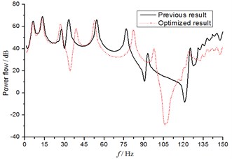
b) The transmitted power flow through the fore stern bearing
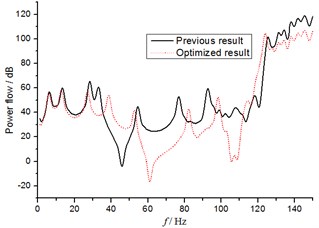
c) The transmitted power flow through the thrust bearing
5. Conclusions
The expression of field transfer matrix of a ship propulsion shafting is deduced based on the modified Timoshenko beam theory using the transfer matrix method. And the power flow of each bearing of the propulsion shafting is carried out numerically. The Pareto optimal solution set is obtained by the optimization algorithm NSGA-II. Then, the Pareto optimal solution set is sorted by the TOPSIS method and MADM approach. The analysis results show that it is feasible and effective to avoid the blindness of selecting optimization results by optimizing the propulsion shafting multi-objectives based on the TOPSIS method and MADM approach.
The research method which is with good guidance can further be applied to multi-parameter multi-objective optimization design of the ship’s structure.
References
-
Wang Bin Effect of bearing stiffness on ship shafting system vibration performance. Journal of Qiqihar University, Vol. 25, Issue 6, 2009, p. 55-60.
-
Zhou Chunliang Vibration Research on Ship Shafting System. Harbin Engineering University, 2006.
-
Hwang C. L., Yoon K. Multiple Attribute Decision Making-Methods and Applications: a State-of-Art Survey. Spring-Verlag, New York, 1981.
-
Shannon C. E., Weaver W. The Mathematical Theory of Communication. The University of Illinois Press, Urbana, 1947.
-
Chen Rong, Wan Chunfeng, Xue Songtao Modification of motion equation of Timoshenko beam and its effect. Journal of TongJi University (Natural Science), Vol. 336, 2005, p. 711-715.
About this article

