Abstract
Sealing disk-baffle integrated structure has been widely applied in modern advanced aero-engines. In this paper, the features of typical sealing disk-baffle integrated structure were analyzed in order to explore the feasible direction of the structure design and optimization. The finite element models were analyzed for the CFM56 series aero-engines [1], and the stress was computed under the different temperature fields, operating speeds and non-linear contacting. The design technologies were summarized for the sealing disk-baffle integrated structure. The results provided bases and references for structure design and engineering applications of the sealing disk-baffle integrated structure.
1. Introduction
The baffle structure confined the turbine blade axial location in the aero-engine turbine, and adjusted the balance of rotor unbalance at the same time [2]. Traditional baffle structures were connected with turbine disks by bolts. With the development of engine design technology, the boltless baffle structure was used in turbine rotor. The sealing disk and baffle were connected to form the cooling air flow in the advanced aero-engine [3].
In 1970s, the GE company had mastered the technology [4] and applied it to CFM56 series engines, it showed that sealing disk-baffle integrated structure represented the development direction of advanced aero-engine in the future [5, 6].
Fig. 1CFM56-3 HPT structure
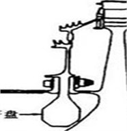
Fig. 2CFM56-5A HPT structure
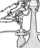
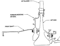
Fig. 3CFM56-7B HPT structure
The research was still relatively scarce about the design technology and optimization for the sealing disk-baffle integrated structure in China. Boltless baffle baffle structures have been used on the turbine components in advanced aero-engines, such as the GE90, F100, Trent 500 and V2500 [7-10]. In China, the parametric design and optimization technology of the boltless baffle structure have been studied by Guihuo Luo and Yongxian Luan in NUAA. The installation techniques of the boltless baffle structure have been researched by Dali Chen and Ming Li [11].
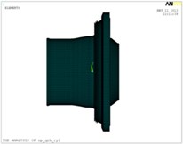
2. Finite element model
The original structure of sealing disk-baffle was made up of two small parts (shown as Fig. 4), finite element model was shown as Fig. 6 and nine contact pairs were defined to simulate the contact between the drum shaft, the sealing disk, the baffle and the turbine disk (red circles in the Fig. 5). The sealing disk was combined with the baffle integrated to form the structure of integrate sealing disk-baffle (shown as Fig. 7), finite element model was established (shown as Fig. 9) and six contact pairs were defined to simulate the contact between the drum shaft, the sealing disk, the baffle and the turbine disk (the red circles in the Fig. 8). The axial and circumferential displacement constraints were applied on the nodes of the inner diameter in the drum shaft according to the boundary conditions, and the radial displacement was allowed on the nodes.
The material was GH4169. The performance parameters of the material could be got by checking out the aeronautical materials handbook. The contact boundary conditions were simulated, and the stress was analyzed by defining contact pairs [12] for the nonlinear contact. TARGE169 and CONTA172 were adopted as contact elements. The thermal stress was calculated with indirect coupling method.
Fig. 4Original structure
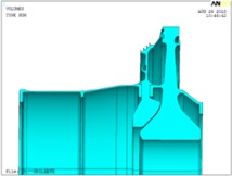
Fig. 5Nine contact pairs on the O.S.
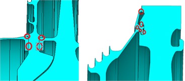
Fig. 6Finite element model of O.S.
Fig. 7Integrated structure
Fig. 8Six contact pairs on the I.S.
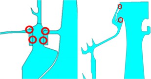
Fig. 9Finite element model of I.S.
3. Comparison and analysis for the two structural stress
For the original structure, the finite element model was shown as Fig. 6, the rotor speed was 14731 rpm (1542.6 rad/s) under maximum load. The stress distributions without temperature field were shown as Figs. 10-14 and Table 1.
Table 1The maximum stress of the original structure assembled
Component | Drum shaft | Sealing disk-baffle | Turbine disk | Structure assembled |
Maximum stress (MPa) | 923 | 1040 | 843 | 1040 |
Margin | 10.4 % | –1.0 % | 18.2 % | –1.0 % |
The value of maximum stress was 923 MPa at the drum shaft of the original structure, which was less than the elastic limit value of material GH4169 at ordinary temperature (1030 MPa), it was shown as the Figs. 10-14 and Table 1, and there was still a margin of 10.4%. The stress value was larger at the right end of the drum shaft than other regions relatively, it showed that much more load was distributed on this part and the strength was weakened relatively. Thus, this region must be designed carefully. The value of maximum stress was 1040 MPa at the sealing disk-baffle of the original structure, which was beyond the elastic limit of the material at ordinary temperature. The position of the maximum stress has occurred at the upper positioning surface place of the baffle. The value of maximum stress was 843 MPa on the turbine disk, which didn’t exceed the elastic limit of material GH4169, and there was still a margin of 18.2 %. The maximum stress was located at the inner diameter of the wheel center on the turbine disk. The value of maximum stress of the assembly was larger than the elastic limit of the material and the structure might fail. The maximum stress appeared at the positioning surface of the baffle and the area was very small. Because of the stress concentration and the cyclic loading, the fatigue failure might occur. Detailed design should be researched on the sealing disk-baffle structure to reduce its stress value and improve the reliability of the aero-engine.
The finite element model was shown as Fig. 9 for the integrated structure, and the rotor speed was 14731 rpm (1542.6 rad/s) under maximum load state. The stress distributions without temperature field were shown as Figs. 15-19 and Tables 2 and 3.
Fig. 10Stress of original structure
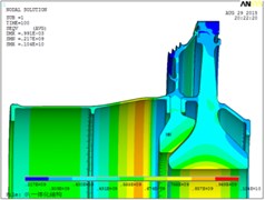
Fig. 11Maximum stress of sealing disk-baffle
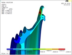
Fig. 12Stress of drum shaft
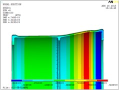
Fig. 13Stress of sealing disk-baffle
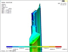
Fig. 14Stress of turbine disk
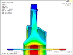
Table 2The maximum stress of the integrated structure assembled
Component | Drum shaft | Sealing disk-baffle | Turbine disk | Structure assembled |
Maximum stress (MPa) | 620 | 910 | 1000 | 1000 |
Margin | 39.8 % | 11.7 % | 2.9 % | 2.9 % |
Fig. 15Stress of integrated structure
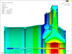
Fig. 16Maximum stress of sealing disk-baffle
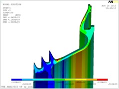
Fig. 17Stress of drum shaft
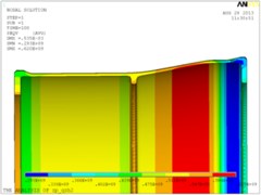
Fig. 18Stress of sealing disk-baffle
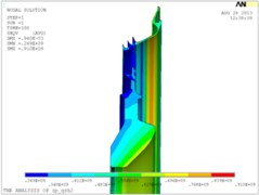
Fig. 19Stress of turbine disk
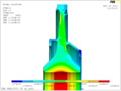
Table 3The comparison of original and integrated structure assembled
Component | Drum shaft | Sealing disk-baffle | Turbine disk | Structure assembled | |
Maximum stress (MPa) | Original | 923 | 1040 | 843 | 1040 |
Integrated | 620 | 910 | 1000 | 1000 | |
Decreased | 32.8 % | 12.5 % | –18.6 % | 3.8 % | |
The maximum stress of the overall configuration was reduced significantly, reference to Table 3. The maximum stress value decreased about 32.8 % from 923 MPa to 620 MPa in the O.S to the I.S, which was far below the elastic limit value of material at ordinary temperature, and the value of the stress was largest at the same place of the drum shaft. The maximum stress reduced about 12.5 % from 1040 MPa to 910 MPa in the O.S. to the I.S. on the sealing disc-baffle, which was less than the elastic limit of material at ordinary temperature, and the stress value was largest at the fillet of the upper labyrinth seal. The maximum stress on the turbine disk increased from 843 MPa to 1000 MPa, which had increased slightly, and the maximum stress occurred at the same place.
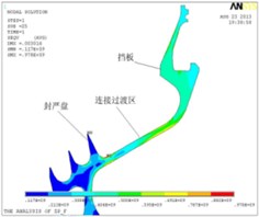
The maximum stress decreased about 3.8 % from 1040 MPa to 1000 MPa for the integrated structure. It was less than the elastic limit value at ordinary temperature and there was still a margin of 2.9 %. The structural strength could be guaranteed basically, but the stress was larger than other regions relatively at transition zone on the sealing disk-baffle. The maximum stress occupied a little area (saw as Fig. 16). There was a phenomenon of stress concentration and the fatigue failure might occur. It is important to carefully design for the region.
4. Optimization of integrated structure
Optimal design was necessary at the transition zone on the sealing disk-baffle based on the stress analysis above. The model was simplified as the 2D axisymmetric finite element model (saw as Fig. 20). The model adopted the PLANE42 axisymmetric element, it was meshed with 7000 elements and 7781 nodes. The stress distributions were shown as Figs. 21-22. The process of optimization was shown as Fig. 23 referencing to foreign advanced aero-engines, and the results were shown as Figs. 24-26 [13, 14].
Fig. 202D finite element model
Fig. 21Stress of 2D model
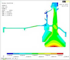
Fig. 22Maximum stress of S.D.B
The maximum stress decreased from 978 MPa to 743 MPa at the transition zone on the I.S after optimal design. It decreased about 24.0 % significantly, and the stress was larger than other regions at the inner diameter of the wheel center. Besides, the stress distribution was uniform and reasonable in the transition zone. There was no stress concentration. The analysis above showed that optimal design of sealing disk-baffle integrated structure was correct and reasonable.
A 3D finite element model was established and calculated to simulate the true structure. The comparative results were shown as Table 4.
The maximum stress value was reduced from 890 MPa to 781 MPa at the sealing disk-baffle integrated structure after optimization design (saw as Table 4), which was less than the elastic limit of the material GH4169 at 500°C (930 MPa) and there was still a margin about 16.0 %. The optimal design could significantly reduce the stress level for the sealing disk-baffle integrated structure, and the optimal ideas and method were correct and reasonable.
Fig. 23Comparison sealing disk-baffle of before and after optimization
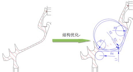
Fig. 24Stress of optimal structure
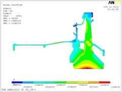
Fig. 25Stress of S.D.B
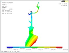
Fig. 26Maximum stress of S.D.B
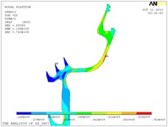
Table 4The comparison stress of before and after optimization
Component | Drum shaft | Sealing disk-baffle | Turbine disk | Structure assembled | |
Maximum stress (MPa) | 3D Before | 633 | 890 | 1070 | 1070 |
3D After | 638 | 781 | 1120 | 1120 | |
2D After | 628 | 747 | 1140 | 1140 | |
5. Conclusions
A series of research and analysis have been conducted on the design and optimal technology of the sealing disk-baffle structure. Main conclusions were listed as follows:
1) The typical sealing disk-baffle integrated structures have been collected and collated; the basic design principles of the typical structures have been researched, which provided a solid foundation for the design and optimization of the sealing disk-baffle integrated structure.
2) The strength analysis has been conducted for the sealing disk-baffle original and integrated structures, and the results of stress have been compared for the three structures. The superiorities have been confirmed and design principles have been researched for the sealing disk-baffle integrated structure.
3) Low stress optimal design were carried out for the sealing disk-baffle integrated structure. The model was selected for parametric and optimal design according to the structural design principles and the influences of operating speed, temperature field and assembly loads. The maximum stress value was decreased about 12.2 %. Stress concentration and the distribution of stress were significantly improved.
The results provide useful references for structure design and engineering applications of the sealing disk-baffle integrated structure. However, the axial and radial coordinate-deformation of the sealing disk-baffle integrated structure should be analyzed and researched. The principles of sealing tolerances will be proposed for the sealing disk-baffle integrated structure in the future.
References
-
Meng Qingdi, Wang Xinge, Han Huiling Calculating research on the centrifugal stress of aero-engine boltless retainer. Aircraft Design, Vol. 30, Issue 4, 2010, p. 45-48.
-
Chen Dali, Li Ming Research of installation technology on the turbine rotor baffles. Chinese New Technology and New Products, Issue 9, 2012, p. 115.
-
Chen Guang Design Analysis of the Aero-Engine Structure. Beijing University of Aeronautics and Astronautics Press, Beijing, 2006.
-
Liang Chunhua Advanced technology of typical modern military and civilian use turbofan engine. Aeronautical Science and Technology, Vol. 2, 2004, p. 20-23.
-
Luan Yongxian, Luo Guihuo Analysis of contact pressure between boltless baffle and blade. Journal of Aerospace, Vol. 22, Issue 9, 2007, p. 1150-1153.
-
Jian Ma, Wenzhou Huang Non-bolted joint between turbine disk and side plate. Experiment and Research of Gas Turbine, Vol. 21, Issue 2, 2008, p. 24-26.
-
Kyohei Horibe, Kouji Kawahira, Jun Sakai, et al. Development of GE90-115B Turbofan Engine. Engineering Review, Vol. 37, Issue 1, 2001, p. 1-8.
-
Mark Turner G. Full 3D Analysis of the GE90 Turbofan Primary Flow Path. GE Aircraft Engines. NASA/CR-2000-209951.
-
Tateno A. GE90 engine. Japan Gas Turbine Journal, Vol. 28, Issue 5, 2000, p. 18-22.
-
Johnson Martin The versatile V2500. Aircraft Engineering and Aerospace Technology, Vol. 69, Issue 6, 1997, p. 561-563.
-
Liang Chunhua Retrofit of the third – generation fighter engines. Aero-Engines, Vol. 30, Issue 4, 2004, p. 53-58.
-
Sinclair G. B., Cormier N. G., Griffin J. H. Contact stresses in dovetail attachments: finite element modeling. Journal of Engineering for Gas Turbines and Power, Vol. 124, Issue 1, 2012, p. 182-189.
-
Dupuis Marc Development and Application of an Ansys Based Thermo-Electro-Mechanical Anode Stub Hole Design Tool. The Minerals, Metals and Materials Society, 2010.
-
Amrita M., Jajimoggala Sarojini Design optimization by using particle swarm optimization in Matlab and APDL in Ansys. International Journal of Engineering Science and Technology, Vol. 4, Issue 5, 2012, p. 1876-1885.
About this article

