Abstract
In this paper, numerical and experimental researches were conducted to explore dynamic characteristics of the floating-ring squeeze film damper. The influences of the eccentricity, radial clearance and width of oil film were considered. Reynolds equations of the inner and outer oil film were derived and solved by finite difference method and SOR-Newton method to obtain pressure distribution of the oil film and thus the equivalent stiffness and damping. Effectiveness of the numerical research was validated by experimental results.
1. Introduction
Squeeze film bearing dampers are lubricated elements providing viscous damping in mechanical systems. Squeeze film dampers in rotating machinery provide structural isolation, reduce the amplitudes of rotor response to imbalance, and in some instances, assist to suppress rotor dynamic instability [1].
Floating-ring squeeze film dampers (FSFD), which is more efficient than traditional SFD, has been applied in aeroengines to control excessive vibration levels of rotors [2] thus to suppress the nonlinear phenomenons, such as amplitude jump and bistability. This, necessites the study on influences of different geometry parameters on the dynamic characteristics of the FSFD.
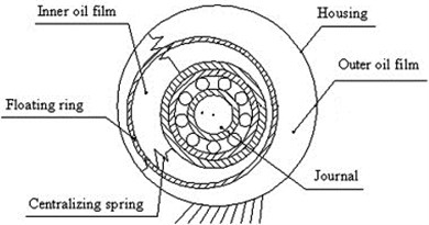
Schematic of the FSFD applied in the work is presented in Fig. 1 [3]. FSFD has two layers of oil film, the inner film and the outer film, which are seperated by the floating ring. The oil films were treated as centralizing springs and coupled dampers.
Fig. 1Schematic of a floating-ring squeeze film damper
2. Basic theory
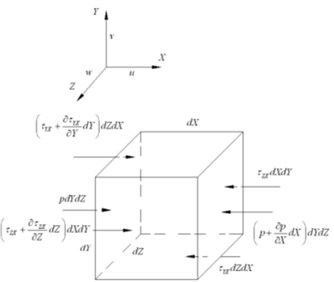
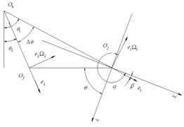
The simplified model of the FSFD is shown in Fig. 2. A small hexahedron is taken for analysis [4], as shown in Fig. 3. The coordinate system consists of three mutually perpendicular axis, X – the circumferential direction, Y – the radial direction and Z – the axial direction [5]. Only the forces acting on axis X were illustrated in Fig. 3. Radius of the journal was 14 mm and width of the oil film was 12.8 mm.
Eq. (1) can be obtained from force balance and Eq. (2) is obtained by simplification of Eq. (1) by neglecting the pressure gradient in radial direction. Integrating Eq. (2) twice, Eq. (3) is obtained.
where, the pressure of oil, the tangential force on X-Z plane and pointed to the X axis direction, the tangential force on X-Y plane and pointed to the X axis direction, the tangential force on Y-Z plane and pointed to the X axis direction, the tangential force on Y-Z plane and pointed to the X axis direction, the tangential force on X-Z plane and pointed to the Z axis direction, the tangential force on Y-Z plane and pointed to the X axis direction, the tangential force on X-Z plane and pointed to the Z axis direction.
Fig. 2The simplified model of FSFD
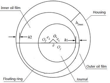
Fig. 3An element of the oil film
where, viscosity of the oil.
where, , , , are integration constants.
The Reynolds Equation, Eq. (4), can be derived by substituting Eq. (3) into the continuity equation of three-dimensional compressible flow.
where, the density of the oil, radial clearance, the speed of journal in circumferential direction, the speed of floating ring in circumferential direction, the speed of journal in radial direction, the speed of floating ring in radial direction.
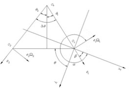
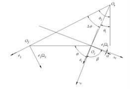
Relative positions of journal, floating ring and housing were illustrated in Fig. 4.
Fig. 4Schematic of the center points relative position
Substituting the boundary conditions of inner and outer film into Eq. (4) to obtain Eq. (5) and Eq. (6).
where, the whirl speed of the journal, the whirl speed of the floating ring, the radius of the journal, the inside radius of the floating ring and , , , , were illustrated in Fig. 4.
where, the outside radius of the floating ring, the radial clearance of the outer film.
The spin speed of the floating ring can be derived by torque balance:
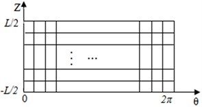
with the short bearing assumption and Reynolds boundary condition, the pressure distribution of the oil film was obtained by finite difference method (FDM) and SOR-Newton iteration method. The grid for FDM is shown in Fig. 5 and Eqs. (8) and (9) are the iteration form of Eqs. (5) and (6).
Fig. 5The divided section of the FSFD
3. Influences of geometry parameters
By numerical simulation, the radial and tangential force were obtained, so was the stiffness and damping. The results were shown in Fig. 6 to Fig. 8
Fig. 6The film forces versus eccentricity
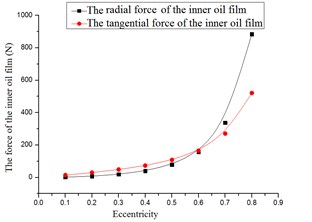
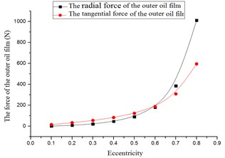
Fig. 7The stiffness versus eccentricity
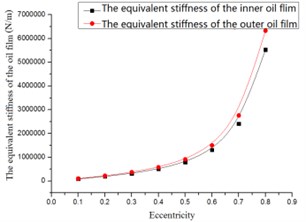
Fig. 8The damping versus eccentricity
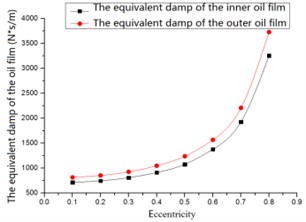
Basically, the forces, equivalent stiffness and damping increased with the eccentricity, as shown in Fig. 6 to Fig. 8. Under the same eccentricity, the forces of the outer oil film were larger than those of the inner oil film. When eccentricity ≥ 0.5, strong nonlinear phenomenon were observed.
With eccentricity = 0.4, the influence of the radial clearance was studied. The results were shown in Fig. 9-11.
Fig. 9The oil film force versus radial clearance
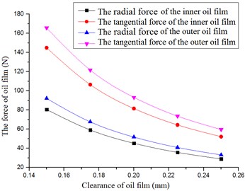
Fig. 10The stiffness versus radial clearance
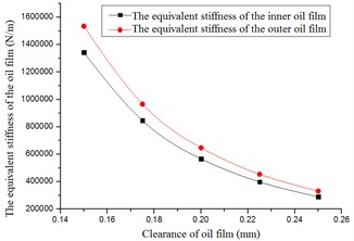
Fig. 11The damping versus radial clearance
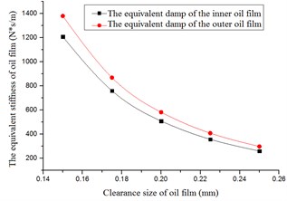
The forces, equivalent stiffness and damping decreased with increase of the radial clearance, as shown in Figs. 9-11. The forces of the outer oil film were larger than those of the inner oil film. The equivalent stiffness and equivalent damping of outer oil film were larger than those of the inner oil film.
Besides the radial clearance and eccentricity, influence of the width of the oil film was studied. The results were shown in Figs. 12-14.
Fig. 12The oil film force versus the width of the oil film
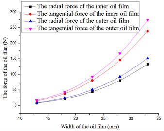
Fig. 13The stiffness versus the width
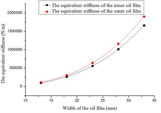
Fig. 14The damping versus the width
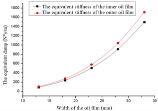
From Fig. 12 to Fig. 14, following conclusions can be reached: the forces, equivalent stiffness and equivalent damping increased with width of the oil film. The forces of the outer oil film were larger than the forces of the inner oil film. The equivalent stiffness and equivalent damping of outer oil film were larger than those of the inner oil film.
4. Experiments
Experiments were conducted to validate the numerical simulation results. Only the outer film pressure was measured in the experiments. The result were shown as Fig. 15 and 16.
Fig. 15The force versus radial clearance
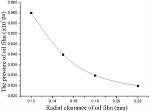
a) The pressure versus clearance-numerical
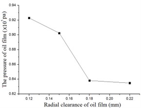
b) The pressure versus clearance-experimental
Fig. 16The force versus the width of the oil film
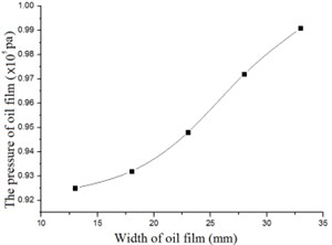
a) The pressure versus the width-numerical
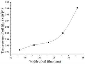
b) The pressure versus the width by experiment
From Fig. 15 and Fig. 16 it can be seen that the numerical results agree well with experimental results. Both numerical and experimental research prove that the pressure of the FSFD increases with width of the oil film and decreases with radial clearance. The coincidence between numerical and experimental results also validate the effectiveness of the numerical method applied in the work.
5. Conclusion
In this paper, numerical and experimental researches were conducted to explore dynamic characteristics of the floating-ring squeeze film damper. The influences of the eccentricity, radial clearance and width of oil film were considered. Reynolds equations of the inner and outer oil film were derived and solved by finite difference method and SOR-Newton method to obtain pressure distribution of the oil film and thus the equivalent stiffness and damping.
By numerical search it was found that the force of the FSFD increased with eccentricity and width of the oil film due to the enhancement in squeezing. Especially when eccentricity > 0.5, strong nonlinearity between force and eccentricity was observed. Although forces of the inner and outer film followed the same pattern, force of the outer film was greater than that of the inner film with the same eccentricity. Besides, influence of the radial clearance was studied. It was found that the force decreased with increasing radial clearance, which was contrary to the eccentricity and width of oil film. Effectiveness of the numerical research was validated by experimental results.
References
-
Zhu Chang Sheng Ability of an advanced hybrid squeeze film damper to control rotor system vibration. Acta Aeronautica et Astronautica Sinica, Vol. 17, Issue 2, 1996, p. 227-233.
-
Hong Jie, Deng Yin, Zhang Dayi Dynamic design method of elastic ring squeeze film damper. Journal of Beijing University of Aeronautics and Astronautics, Vol. 32, Issue 6, 2006, p. 649-653.
-
Wen Bangchun, Gu Jialiu Senior Rotor Dynamic. First Edition, China Machine Press, China, 2000.
-
Liang Dewang, Basic Hydrodynamics. First Edition, Aviation Industry Publishing House, China, 1998.
-
Cao Lei, Gao De-ping, Jiang He-fu Damping mechanism of elastic ring squeeze film damper. Journal of Vibration Engineering. Vol. 20, Issue 6, 2007, p. 584-588.
About this article

