Abstract
A challenge with existing WSNs used for structural health monitoring (SHM) is how to increase the data transmission rate (DTR) for large amounts of sampling data. To handle this issue, this paper proposes a new design method of a high-throughput WSN with multi-radio sink node (M-RSN) which can increase the data transfer ability of WSN. Additionally, a tight scheduled approach and multi-radio time synchronization method are designed for the stable implementation of the proposed network. A high data throughput of 1020 Kbps of the developed network has been proved. To evaluate the effectiveness and robustness of the proposed network designing method, experiments for aircraft composite wing boxes monitoring are carried out. The evaluation results have shown the advantages of the proposed methods.
1. Introduction
Structural health monitoring (SHM) based on wireless Sensor Network (WSN) has been considered as an active area in recent years. In comparison with traditional cable-based monitoring systems, WSN-based monitoring systems have advantages of less weight, low-cost manufacturing, distributed operation and more convenient deployment. These advantages make WSN-based monitoring systems more adoptable for many applications [1, 2], particularly for SHM area [3-7]. The researches performed so far include various nodes design [3, 4], WSN based SHM systems design and their evaluations on different structures [5-7].
However, the implementation of WSN-based SHM monitoring system still meets challenges with improving the data transmission rate (DTR) for large amount of data collection. High DTR is required in many applied scenarios of WSNs in SHM areas [8, 9]. Pakzad et al. reported the application of monitoring the Golden Gate Bridge deployed by a WSN which consists of 64 accelerometers [9]. In the research, the full network produced 20 MB of data and took about 9 hours to transfer the data after a complete cycle of sampling and data collection.
In WSNs, data from each cluster of sensor nodes are finally received by the sink node. The sink node transfers these data to computer which processes the data more efficiently. Hence, the ability of the sink node plays a significant role in improving DTR of WSNs. Some literatures have reported the improvement of DTR in WSNs by using high-performance sink node [10-14]. Simulations have indicated that multi-channel communication in sink node can improve the DTR by transferring data in different communication channels [15-17]. However, many multi-channel assignments for WSNs are based on the sink node which contains only one radio module. Adya et al. discussed this problem and pointed out that the DTR in network is still limited because the sink node with single radio has to be constantly switched to different channels [16]. Bahl et al. investigated that multi-radio platform can contribute to data capacity improvement in WSNs [18]. Kohvakka et al. [10] and the authors’ group [14] presented the developments of multi-radio sink nodes for IEEE 802.11 and IEEE 805.15.4 respectively. When multiple radios are adopted in the sink node, switching among different channels is eliminated and data flowing can be received constantly from senders to the receiving radio interfaces, which can greatly improve the DTR. Yuan et al. proved that the maximum DTR of a CC2420 transceiver of IEEE 802.15.4 is 135 Kbps [14]. When all the 7 transceivers are operated together, the DTR in the authors’ research can reach 909.3 Kbps. Although these researches have concentrated on the design of the multi-radio nodes, relatively less attention is paid to deep research on designing WSNs based on these nodes.
The article is organized as follows. First, the software and hardware implementations of M-RSN are presented. Then, a new design method for multi-radio network is presented. This method develops multi-radio communication with high-throughput ability by M-RSN. Subsequently, a tight scheduled approach combined with time synchronization for the network is discussed. Then, experiment verifies the maximum DTR of the designed network. Further, in order to verify the ability to develop structural health monitoring systems based on the designed network, a distributed strain WSN-based monitoring system is implemented on a wing box and an unmanned aerial vehicle (UAV) composite wing together which are both real complex aerospace structures.
2. Design of the high-throughput network
2.1. The design of multi-radio sink node and wireless strain sensor node
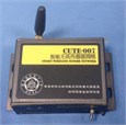
Fig. 1(a) shows that the dimension of M-RSN [14] is 180 mm×115 mm×30 mm. The hardware of M-RSN, presented in Fig. 2(a), mainly contains core processing module, multiple wireless communication modules, universal serial bus (USB) communication module.
Once M-RSN starts up the supplying power, core processing module initializes and controls the operation of multiple wireless communication modules and USB communication modules. A wireless communication module is in charge of starting network operation by sending command to all sensor node and broadcasts synchronization command periodically to all sensor nodes for synchronizing network. The other wireless communication modules receive data from sensor nodes and transfer sensor data to core processing module.
The core processing module of M-RSN controls the operation of other communication module. It adopts a FPGA chip (EP3C16Q240C8N) from ALTERA Company as the core processor. This chip contains 240 physical pins, and these pins provide enough efficiency of parallel data transmission for other communication modules.
The USB module connects to FPGA chip with SLOE, SLRD and SLWR pins which indicate the state of reading or writing data. The data bus FD [7:0] and address bus FIFOADDR [7:0] are used to data transmission between FPGA chip and CY7C68013A chip.
The multiple wireless communication modules adopt a 2.4 GHz CC2420 radio chip and connect to core processing module with SFD, FIFO, FIFOP and CCA pins which can indicate the state of receiving or sending data. In this paper, two kinds of wireless communication modules operate in M-RSN. One wireless communication module with 32.768 kHz oscillator is only used as synchronization manage module (SMM). The other wireless communication modules with 50 MHz oscillator are only used for receiving radio data from sensor nodes.
Fig. 1(b) shows the wireless strain sensor node adopted which are developed by the authors’ group [3]. The node contains strain gauge signal conditioning board and core board. In the core board, a low-power microcontroller MSP430F1611 is selected as processing controller and CC2420 chip is selected as radio transceiver. 4 channel converters with 12-bit analog-to-digital conversions (ADC) precision in MSP430F1611 MCU allow the node to simultaneously sample analog signals from multiple strain sensors. The signal conditioning board is composed of bridge circuit, amplifier and output circuit for strain signals conditioning.
Fig. 1Implementations of the multi-radio sink node and Wireless Strain sensor node

a) Wireless strain sensor node
b) Multi-radio sink node
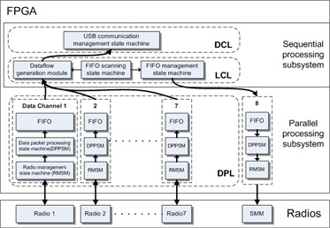
Fig 2(b) shows the software structure of the sink node. The software structure consists of data processing layer (DPL), logic control layer (LCL) and data communication layer (DCL). DPL includes RF module management state machine and data packet processing state machine. RF module management state machine is used to initialize the RF module, responds to the interrupt signal from the RF module when it receives a data packet and resets RF module when an error happens. The data packet processing state machine handles with the data packet in the light of the HDLC protocol and CRC code. LCL includes FIFO scanning state machine, FIFO management state machine and dataflow generation module. By merging reading data packets in different RF modules and processing the data flow, the LCL trades off low RF modules working efficiency against the improvement of network throughput. In DCL, USB communication management state machine which connects the USB chip to FPGA chip. It configures the registers and interfaces of USB chip and provides a transmission channel for data flow from all radios.
Fig. 2Software and hardware diagram of multi-radio sink node
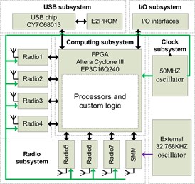
a) Hardware diagram of multi-radio sink node
b) Software diagram of multi-radio sink
2.2. The framework and scheduled approach for the Network
To achieve the high DTR WSN based SHM, a WSN architecture that features multi-radio communication is presented.
Fig. 3 shows the topology of multi-radio wireless network with high DTR ability. In the network, wireless strain sensor nodes are arranged into several clusters in different structure locations. In each cluster, the sensor nodes are in charge of strain acquisition and communicate in the same channel. Especially, the sensor nodes forward the data towards the multi-radio sink node. To avoid conflictions, sensor nodes in different clusters work in different communication channels. There are totally 48 different available channels.
A radio transceiver, namely manage module in M-RSN is in charge of starting the operation of the whole network by sending initial command. During the working state, the proposed M-RSN receives data packets from multiple clusters which work in multiple communication channels simultaneously. The manage module is designed to start, suspend and stop the operation of network.
Time synchronization is indispensable in majority of real-time monitoring systems based on WSNs. Time synchronization occurs to adjust time jitter of the sensor node’s clocks, which is necessary to determine the reliability of sensing alignment and facilitate the tight scheduling TDMA protocol of sensor data delivery in each channel.
3. Evaluation experiments
3.1. Data throughput evaluation experiment
In order to evaluate the DTR, the baseline DTR between two nodes with single-radio is discussed first. Theoretically, 250 Kbps is reported between 2 CC2420 radio based nodes. If the packet copying is performed between the transceiver and the microcontroller during real data sampling and sending procedure, the maximum DTR is only around 140 Kbps. The maximum DT of radios is 114.2 Kbps on Iris platform respectively [11].
Fig. 3The topology of multi-radio wireless network
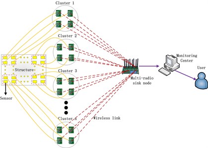
Fig. 4Data throughput experiment setup
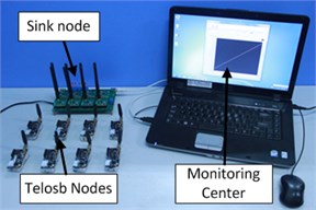
An experiment system is established as shown in Fig.4. In the experiment, besides the developed M-RSN, 8 Telosb nodes are adopted to send data to the M-RSN. There are 48 communication channels provided by CC2420 radio. In order to reduce the mutual interference among different channels, only odd numbered channels are adopted in the experiment, namely Channel 11, 13, 15, 17, 19, 21, 23 and 25. Under this situation, every adopted channel can keep at least one channel interval with other used channels. After initialization of the leaf node, a fixed packet is written directly into the transmit FIFO (TXFIFO) of the CC2420 chip on the leaf node. The size of the fixed packet is 127 bytes.
During the experiment, data throughputs when different numbers of Telosb nodes are activated to send data respectively from 1 to 8 are tested, as shown in Table 1. The maximum throughput when only one channel is used is 135.7 Kbps. When all the 8 radios are used together, the maximum throughput can reach 1020 Kbps which is significantly improved compared to the maximum data throughput of ordinary 2.4 GHz radio sink node.
Table 1Data throughput evaluation results of the multi-radio network
Channel | 1 | 2 | 3 | 4 | 5 | 6 | 7 | 8 |
Throughput (Kbps) | 135.7 | 262.2 | 397.3 | 528.4 | 655.4 | 774.1 | 909.3 | 1020 |
3.2. Strain monitoring evaluation for UVA composite wing structure
Structure strain changes under external or mechanical loads are important testing parameters in SHM. The aircraft static strain test, on-board strain measurement during test flight and certification of a new aircraft are critical in aircraft structure testing. It is important to measure the load strain at key locations during tests, measure strain distributions during compression testing of stiffened panels with damage to validate analytical model predictions.
The experiment consists of 7 sensor nodes clusters in different channels, in which cluster 1, 2, 3, 4 and 5 are in charge of strain monitoring of UAV composite wing structure and cluster 6, 7 are dedicated for the strain monitoring of wing box structure. Each cluster contains 4 strain sensor nodes. Fig. 5(a) demonstrates the arrangements of strain sensor nodes on the wing box structure. The structure includes 5 lines of bolt holes with an interval distance of 280 mm and 6 T shape stiffeners with an interval distance of 130 mm. As shown in Fig. 5(a), a central monitoring area without bolt holes and shape stiffeners is chosen for strain monitoring and its size is 280×130 mm2. In the structure, the strain gauges connected to No. 11, 12, 13, 14, 21, 22, 23, 24, 31, 32, 33, 34, 41, 42, 43 and 44 sensor nodes are placed on the monitoring area.
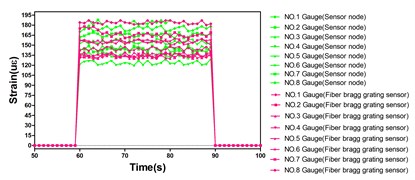
The UAV composite wing structure and the arrangement of nodes are shown in Fig. 5(b). NO.61, 62, 63, 64, 71, 72, 73 and 74 strain gauges and No. 1, 2, 3, 4, 5, 6, 7 and 8 fiber bragg grating sensors are placed on the beam in UAV composite wing structure. Each fiber bragg grating sensor is deployed besides each strain gauges for strain data comparison. As spectral filter, fiber bragg grating sensor is based on the principle of Bragg reflection. The gratings are printed in the core of optical fiber in a parallel and close line. The gratings alternate regions of high and low refractive indices when a periodic ultraviolet light is imposed on optical fibers. The wavelength is known as the bragg wavelength and is given by where is the average refractive index and is the grating period. When load is applied to the UAV composite wing structure, 8 grating is strained and the peak reflected wavelength is changed. In this experiment, change of reflected wavelength without temperature compensation is given by:
where is the initial reference wavelength, is the wavelength shift, is the effective index of the refraction of the core, is poisson’s ratio of fibre, and are gauge constants of the strain optic tensor, and represents in total the gauge factor of fibre. As fiber bragg grating sensor, Micron os3610 is chosen with the size of 19 mm×250 mm. The strain ranges from –2500 με to +2500 με and the strain sensitivity is 1.2 pm/με. The gauge factor equals to 0.8. A high speed optical sensing interrogator unit (SM130-700 Micron Optics, scanning rate 1 kHz, 8 optical channels, center wavelength of 1550 nm, wavelength ranges from 1510 nm to 1590 nm) is used to demodulated the bragg wavelength shift , and then strain is calculated by Eq. (6). In this way, the fiber bragg grating works as strain sensor.
Fig. 5Strain monitoring experiment setup for aircraft structure
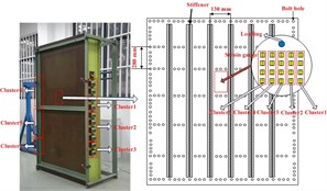
a) Experiment arrangement of the wing box
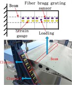
b) Experiment arrangement of the UAV composite wing
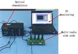
c) Monitoring center setup of the experiment
Fig. 6Strain monitoring results for Aircraft structure
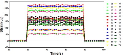
a) Strain results from 28 nodes in 7 channels
b) The comparison of strain results between strain gauges and fiber bragg grating sensor gauge
Two loading equipment (CHHBL2) are used to change the strain distribution on UAV composite wing structure and wing box structure respectively. When concentrated load applied on structure is changed, the strain distribution will be changed. Two loads are exerted by screw rod and increased with screw rod rotated. Initially, screw rod is rotated for two cycles to serve as preload on wing box or UAV composite wing. Then, the load increases gradually with rotating the screw rod. Once the strain displayed on the computer is stable, it will be sampled for 5 seconds and averaged. The averaged strain value is used as final strain value. In Fig.5(c), M-RSN, SM130-700 optical sensing interrogator unit and PC monitoring are deployed together for the distributed strain monitoring of the wing box structure and UAV composite wing structure.
The distributed strain test result of 28 curves from 28 strain nodes in 7 different channels is shown in Fig. 6(a). Each curve demonstrates strain value of a sensor node for one strain gauge attached on the UAV composite wing structure or the wing box structure. Each plot value is an average value of 50 sampling point data. Initially, no load is applied on the two structures, so the strain values from all sensor nodes are zero. At time 60 s, two loads are respectively applied on the two structures simultaneously and all the 28 strain nodes have simultaneous outputs. Since different strains are produced at different positions on the two structures, the strain value output of each node is different. When time arrives at 90 s, all loads are removed from two structures. Under this circumstance, each sensor node in the network is able to monitor the loading changes at the same time. In the processing, the change data are successfully forwarded to the M-RSN and displayed in the central computer system.
Besides the strain monitoring experiment above, in UAV composite wing structure, another strain monitoring experiment is carried out by 8 fiber bragg grating sensors connected to the SM130-700 optical sensing interrogator unit. The loading process is repeated and the strain measurement is implemented again. Then, as shown in Fig. 6(b), 8 strain testing results from SM130-700 optical sensing interrogator unit are compared to the strain results of No. 61, 62, 63, 64, 71, 72, 73 and 74 sensor nodes obtained by designed network. It is concluded that the strain data obtained from the designed network are almost the same as that of optical demodulator, verifying the accuracy of the designed network. These results further prove the multi-radio simultaneous communication ability of the developed monitoring network applied in the UAV composite wing structure and the wing box structure.
4. Conclusions
To solve the bottleneck problem of high DTR WSN-based SHM, this paper proposes a new design of WSN. A multi-radio network increasing the data transfer ability at the sink is proposed for WSN. Additionally, a tight scheduled approach and adequate multi-radio time synchronization are introduced for the proposed network. Experimental validations on wing box and UAV composite wing structure show the high DTR in WSN-based SHM. This kind of WSN shows its great potential applied value and easily deployment in large-scale SHM applications. In the future, we will extend the network and improve the data transfer ability of the approach to reduce transmission time for SHM applications.
References
-
Huang H., Paramo D., Dushmukh S. Unpowered wireless transmission of ultrasound signals. Smart Materials and Structures, Vol. 20, 2011 p. 015017.
-
Akyildiz I. F., Melodia T., Chowdhury K. R. A survey on wireless multimedia sensor networks. Computer Networks Journal, Vol. 51, Issue 4, 2006, p. 921-960.
-
Wu J., Yuan S. F., Zhao X. A wireless sensor network node designed for exploring a structural health monitoring application. Smart Materials and Structures, Vol. 16, 2007, p. 1898-1906.
-
Lynch J. P. Design of a wireless active sensing unit for localized structural health monitoring. Structural Control and Health Monitoring, Vol. 12, Issues 3-4, 2005, p. 405-423.
-
Wu J., Yuan S. F. Design and evaluation of a wireless sensor network based aircraft strength testing system. Sensors, Vol. 9, Issue 6, 2009, p. 4195-4210.
-
Lynch J. P., Wang Y., Loh K., Yi J. H., Yun C. B. Wireless structural monitoring of the Geumdang bridge using resolution enhancing signal conditioning. Proceedings of the 24th International Modal Analysis Conference, 2006.
-
Liu Zhiqiang, Yu Yan, Liu Gao Design of a wireless measurement system based on WSNs for large bridges. Measurement, Vol. 50, 2014, p. 324-330.
-
Cosar E. I., Bocca M., Eriksson L. M. High speed portable wireless data acquisition system for high data rate applications. Proceedings of the ASME 2009 International Design Engineering Technical Conferences and Computers and Information in Engineering Conference, 2009.
-
Pakzad S. N., Fenves G. L., Kim S., Culler D. E. Design and implementation of scalable wireless sensor network for structural monitoring. Journal of Infrastructure Systems (ASCE), Vol. 14, 2008, p. 89-101.
-
Kohvakka M., Arpinen T., Hannikainen M., Hamalainen T. High-performance multi-radio WSN platform, REALMAN. Proceedings of the 2nd ACM International Workshop on Multi-hop Ad Hoc Networks: From Theory to Reality, 2006.
-
Jurdak R., Klues K., Kusy B., Richter C., Langendoen K., Brunig M. Opal: a multiradio platform for high throughput wireless sensor networks. IEEE Embedded Systems Letters, Vol. 3, Issue 4, 2011, p. 121-124.
-
Gummeson J., Ganesan D., Corner M. D., Shenoy P. An adaptive link layer for heterogeneous multi-radio mobile sensor networks. Proceedings of the IEEE JSAC, 2010.
-
Popovici E., Boyle D., O’Connell S. The s-mote: a versatile heterogeneous multi-radio platform for wireless sensor networks applications. 20th European Conference on Circuit Theory and Design (ECCTD), 2011.
-
Yuan S. F., Wang Z., Qiu L. A multi-radio sink node designed for wireless SHM applications. Smart Structures and Systems, Vol. 11, Issue 3, 2013, p. 261-282.
-
Vassis D., Kormentzas G., Skianis C. Performance evaluation of single and multi-channel actor to actor communication for wireless sensor actor networks. Ad Hoc Networks, Vol. 4, 2006, p. 487-98.
-
Adya A., Bahl P., Padhye J., Wolman A., Zhou L. A multi-radio unification protocol for IEEE 802.11 wireless networks. Proceedings of the First International Conference on Broadband Networks, 2004, p. 344-354.
-
Campbell C. E. A., Khan S., Singh D. Multi-channel multi-radio using 802.11 based media access for sink nodes in wireless sensor networks. Sensor, Vol. 11, Issue 5, 2011, p. 4917-4942.
-
Bahl P., Adya A., Padhye J., Wolman A. Reconsidering wireless systems with multiple radios. Computer Communication Review, Vol. 34, Issue 5, 2004, p. 39-46.
About this article

