Abstract
A finite element model was constructed for a dual-rotor structure based on a certain aero-engine in this paper. Its dynamic characteristics was calculated and analyzed with the finite element software ANSYS. The characteristics were contrasted and analyzed for the dual-rotor structure with four bearings or five bearings. The influence was discussed and analyzed about the change of bearing’s stiffness to dynamic characteristics. The main conclusion was concluded as following: the low-pressure rotor vibrated in the first bending mode for the first and second modal shape; the critical speed gradually increased as the stiffness, it behaved obviously during a certain range of the stiffness, and meanwhile some modal shape would disappeared.
1. Introduction
The models were constructed for the dual-rotor structures with four bearings or five bearings. The forms were shown as Table 1 for the five supporting programs.
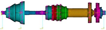
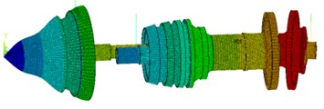
The five finite element models were shown as Figs. 1-5, which corresponds to the five supporting programs in Table 1.
Table 1The forms for the five supporting programs
Supporting program | High-pressure rotor | Low-pressure rotor | The thrust bearing |
Four bearings | 1-0-1 | 0-1-1 | Bearing 1, bearing 2 |
Five bearings | 1-0-1 | 0-2-1 | Bearing 1, bearing 3 |
1-0-1 | 0-2-1 | Bearing 2, bearing 3 | |
1-0-1 | 1-1-1 | Bearing 2, bearing 3 | |
1-0-1 | 1-1-1 | Bearing 2, bearing 3 |
Fig. 1The four bearing dual-rotor structure
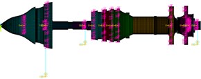
Fig. 2The 1st five bearing dual-rotor structure
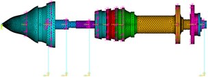
Fig. 3The 2nd five bearing dual-rotor structure
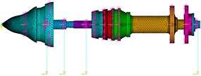
Fig. 4The 3rd five bearing dual-rotor structure
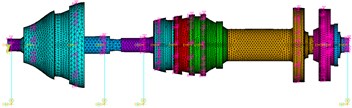
Fig. 5The 4th five bearing dual-rotor structure
2. The finite element model
The bearing 1, bearing 2, bearing 3, bearing 4, bearing 5 separately represented the five bearings from the left side to the right side of the dual-rotor structures shown as Figs. 2-5; Bearing 4 is the intermediate bearing. The low-pressure rotor’s supporting program became 0-1-1 for four bearing structure shown as Fig. 1. The mass and the moment of inertia of the blades of the compressor and turbine were represented by the mass21 element, which located in the spin axis of the dual-rotor and connected to the solid185 element of the corresponding plate by the command ‘CERIG’.
3. Dynamic characteristics comparing for the dual-rotor structures of different supporting programs
The critical speeds, modal shapes and strain energy distribution were analyzed respectively. The similarities and differences were contrasted and analyzed for the dual-rotor structures with different supporting programs.
3.1. Analysis of dynamic characteristics for the dual-rotor structures with the four bearings
The rotational speed ratio of high-pressure rotor and low-pressure rotor was assumed as –1.48, while the minus sign expressed opposite rotation for the dual rotors. The Campbell graph was shown as Fig. 6 for the dual-rotor structure with four bearings. The first three order critical speeds were shown as Table 2.
For the first modal shape, the low-pressure rotor orbited in the first bending mode; its amplitude reached maximum at the end of turbine; the turbine and the compressor deflected around their diameter; the high-pressure rotor vibrated with relative small amplitude. For the second modal shape, the low-pressure rotor compressor vibrated in a pitching way. For the third modal shape, the high-pressure rotor compressor vibrated in a pitching way, the low-pressure rotor vibrated in a mode similar to the first bending mode. The first three order modal shapes were shown as Table 3.
Fig. 6Campbell graph for the dual-rotor structure with four bearings
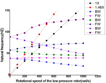
Table 2The first three order critical speeds
Critical speed (rpm) | Whirling synchronously with the low pressure rotor | Whirling synchronously with the high pressure rotor |
First order | 2299.2 | 2268.0 |
Second order | 3222.6 | 3134.4 |
Third order | 5090.4 | 4638.0 |
3.2. Analysis of dynamic characteristics for the dual-rotor structures with different supporting programs
The critical speeds were shown as Table 4 for the dual-rotor structures with different supporting programs.
The critical speeds of the dual-rotor structures with the 3rd and the 4th five bearings supporting programs were significantly higher than others for the first and second modal shape; it indicated that the 1-1-1 supporting program could enhance the dual-rotor structure’s rigidity comparing with the 0-2-1 and 0-1-1 supporting program. The computing results were nearly same for the 1st and 2nd five bearings programs with each other, and whether bearing 1 or bearing 2 as the thrust bearing didn’t matter when the critical speeds were taken into account. The local part of the shaft of the second bearing was hardly vibrating for the dual-rotor structure with the 1st and 2nd five bearings supporting programs, and the second bearing didn’t contribute anything for the rigidity of the dual-rotors, because the part located the nodal point for the dual-rotor structure according to the first or second modal shape. The arrangement of the first bearing was better than the five bearings relatively to the four bearings. The critical speeds were higher for the four bearings than for the 1st and 2nd five bearings, so the location of the bearing could be optimized.
Table 3The first three order modal shapes
Whirling synchronously with the low-pressure rotor | Whirling synchronously with the high-pressure rotor | |
First order | 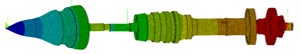 |  |
Second order | 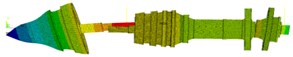 | 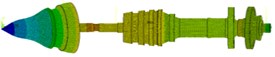 |
Third order |  | 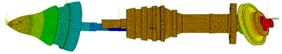 |
Table 4The critical speeds for the dual-rotor with different supporting programs
Supporting program | Whirling synchronously with the low-pressure rotor (rpm) | Whirling synchronously with the high-pressure rotor (rpm) | ||||
1st order | 2nd order | 3rd order | 1st order | 2nd order | 3rd order | |
Four bearings | 2299.2 | 3222.6 | 5090.4 | 2268 | 3134.4 | 4638 |
1st five bearings | 2275.8 | 3035.4 | 6438 | 2265 | 3007.2 | 6228 |
2nd five bearings | 2275.8 | 3035.4 | 6438 | 2265 | 3007.2 | 6228 |
3rd five bearings | 2484 | 4573.8 | 6408 | 2479.8 | 4566 | 6144 |
4th five bearings | 2383.8 | 4814.4 | 5770.2 | 2382 | 4694.4 | 5573.4 |
Fig. 7The energy distribution for four bearings dual-rotor structure
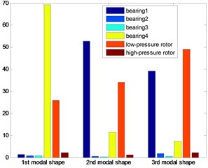
Fig. 8The energy distribution for 1st five bearings dual-rotor structure
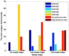
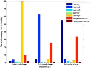
The distributions of strain energy were shown as Figs. 7-11: nearly 70 % energy was undertaken by the last bearing for the first modal shape; about 90 % energy by the first and last bearing and the low-pressure rotor for the second modal shape of the first three dual rotor structure. More than the 90 % energy concentrated on the 1st and 2nd bearings for the 3rd five bearings dual-rotor, and the alike energy on the 1st and 2nd and low-pressure rotor for 4th five bearings dual-rotor; about the 90 % energy concentrated on the first bearing and the low-pressure rotor for four bearings, and the same on the 4th five bearings dual-rotor for the third modal shape. About the 40 % energy was undertaken by the first three bearings for the other five bearings dual-rotor structures, about the 30 % energy was undertaken by the high-pressure rotor for the 1st five bearing dual-rotor. As the bearings generally undertake the strain energy as much as possible, the location and stiffness could be optimized for to reduce the energy on the rotors and increase the energy on the bearings.
Fig. 9The energy distribution for 2nd five bearings dual-rotor structure
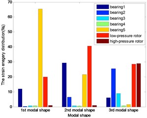
Fig. 10The energy distribution for 3rd five bearings dual-rotor structure
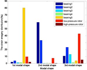
Fig. 11The energy distribution for 4th five bearings dual-rotor structure
4. The analysis for the change of the bearing’s stiffness to the critical speeds
The dynamic characteristics was researched for the only one bearing of the dual-rotor structures once time, the similarities and differences were analyzed and compared.
4.1. The influence of the stiffness of bearing 1
The changes of the first three order critical speeds were shown as Figs. 12 and 13, where the stiffness of bearing 2, bearing 3 and bearing 4 as constant, the stiffness of bearing 1 as a variable.
4.2. The influence of the stiffness of bearing 2
The changes of the first three order critical speed were shown as Figs. 14 and 15, where the stiffness of bearing 1, bearing 3 and bearing 4 as constant, the stiffness of bearing 2 as a variable.
4.3. The influence of the stiffness of bearing 3
The changes of the first three order critical speed were shown as Figs. 16 and 17, where the stiffness of bearing 1, bearing 2 and bearing 4 as constant, the stiffness of bearing 3 as a variable.
4.4. The influence of the stiffness of bearing 4
The changes of the first three order critical speed were shown as Figs. 18 and 19, where the stiffness of bearing 1, bearing 2 and bearing 3 as constant, the stiffness of bearing 4 as a variable.
Fig. 12Whirling synchronously with the low-pressure rotor
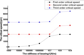
Fig. 13Whirling synchronously with the high-pressure rotor
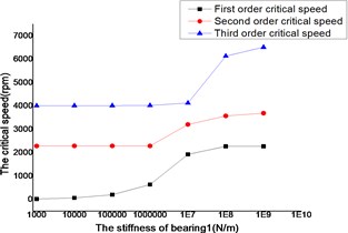
Fig. 14Whirling synchronously with the low-pressure rotor
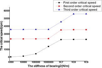
Fig. 15Whirling synchronously with the high-pressure rotor
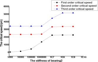
Fig. 16Whirling synchronously with the low-pressure rotor
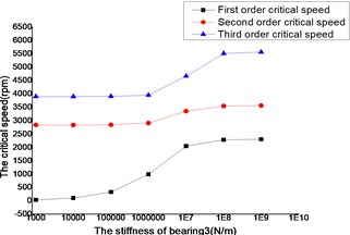
Fig. 17Whirling synchronously with the high-pressure rotor
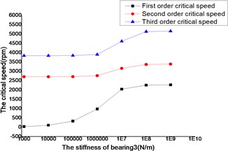
Fig. 18Whirling synchronously with the low-pressure rotor
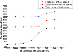
Fig. 19Whirling synchronously with the high-pressure rotor
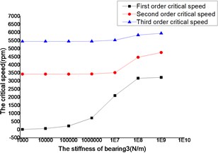
The critical speed increased as the stiffness of the bearings, which were shown as Figs. 12-19. It behaved obviously among a certain range of the stiffness. Some modal shape of the dual-rotor structures disappeared as the stiffness of the bearings increased. Some higher order modal shape for the small stiffness was similar to the lower order modal shape for the big stiffness. For example, the first modal shape disappeared when the stiffness was changed from 1×10³ N/m to 1×10⁹ N/m for bearing 2, the first order modal shape was similar to the second order modal shape in the former case, and the corresponding modal shapes were shown as Figs. 20 and 21.
Fig. 20The 1st modal shape when K2= 1×10⁹ N/m
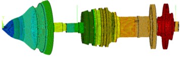
Fig. 21The 2nd modal shape when K2= 1×10³ N/m
5. Conclusions
1) The low-pressure rotor vibrated in the first bending mode for the 1st and 3rd modal shape and vibrated in a pitching way for the 2nd modal shape; the high-pressure rotor vibrated in a pitching way for 3rd modal shape.
2) The strain energy mainly concentrated in the last bearing for the first modal shape, the first and second bearing undertook some energy for the second order modal shape; most of the strain energy concentrated on the first bearing and the low-pressure rotor for the four bearing dual-rotor for the third order modal shape; The first three bearings undertake some energy for the five bearing dual-rotor.
3) The 1-1-1 program was the best way to increase the rigidity of the dual-rotor structure; when the supporting program of the low-pressure rotor was 0-2-1, it is doesn’t matter to the critical speed whether first or second bearing was thrust bearing; If the bearing can’t be arranged in a reasonable place, the rigidity may be lower than the four bearing dual-rotor’s for the five bearing dual-rotor structure.
4) The critical speed of the dual-rotor increase as the stiffness of the bearing, but it behaved significantly just in a certain range of the bearing’s stiffness.
5) Some modal shape disappeared with the increase of the bearing’s stiffness for the dual-rotor for the small stiffness; some higher order modal shape for small stiffness was similar to the lower order modal shape for the big bearing’s stiffness.
References
-
Feng Guoquan, Zhou Baizhuo, Luo Guihuo Vibration characteristic investigation of counter-rotating dual-rotor in aero-engine. Transactions of Nanjing University of Aeronautics and Astronautics, Vol. 29, Issue 1, 2012, p. 33-39.
-
Fei Zhong-Xiu, Tong Shui-Guang, Wei Chao, et al. Investigation of the dynamic characteristics of a dual rotor system and its start-up simulation based on finite element method. Journal of Zhejiang University – Science A (Applied Physics and Engineering), Vol. 13, Issue 4, 2013, p. 268-280.
-
Hamed Y. S., Sayed M., Cao D.-X., et al. Nonlinear study of the dynamic behavior of a string-beam coupled system under combined excitations. The Chinese Society of Theoretical and Applied Mechanics and Springer – Verlag Berlin Heidelberg, Vol. 27, Issue 6, 2011, p. 1034-1051.
-
Wei Li, Yi Yang, De-ren Sheng, et al. Nonlinear dynamic analysis of a rotor/bearing/seal system. Journal of Zhejiang University-Science A (Applied Physics and Engineering), Vol. 12, 1, p. 45-55.
-
Feng Shi, Jian-Biao Du, Li Cheng The Studies on the dynamics of the double-rotors system. Machinery and Electronics, Issue 10, p. 56-58, (in Chinese).
-
Chen Guo Vibration modeling and analysis for dual-rotor aero-engine. Journal of Vibration Engineering, Vol. 24, Issue 6, p. 621-632, (in Chinese).
-
Deng Si-Er, He Feng-Xiang, Yhang Hai-Sheng, Li Yun-Long Analysis on dynamic characteristics of a dual rotor-rolling bearing coupling system for aero-engine. Journal of Aerospace Power, Vol. 25, Issue 10, p. 2386-2395, (in Chinese).
-
Chen Jing-Ming, Jiang Dong-Xiang, Xu Hong-Zhi Efficient fault identification method for dual rotor-supporting system using model-based method. Journal of Aerospace Power, Vol. 28, Issue 12, p. 2797-2802, (in Chinese).
-
Han Jun, Gao Deping, Hu Xuan, Chen Gaojie Research on beat vibration of dual-rotor for aero-engine. ACTA Aeronautica et Astronautica Sinica, Vol. 28, Issue 6, p. 1370-1373.
-
Hong Jie, Wang Hua, Xiao Da-wei, Chen Meng Effects of dynamic stiffness of rotor bearing on rotor dynamic characteristics. Aeroengine, Vol. 34, Issue 1, p. 23-27.
About this article

