Abstract
The paper deals with the problem of reliability of continuous vibration monitoring process of wind turbines. As a solution authors propose the approach based on the accreditation of the method with reference to requirements of the standard ISO 17025:2005. As equipment, measurement traceability and the handling of test and calibration items influence the testing process there is also presented a procedural, exemplary approach to intermediate checks of temperature measurement instruments.
1. Introduction
Wind power, one of the green, safe and low-carbon energy, is so fast-developing in generating electricity that it has become the fourth major power source after coal, water and nuclear [1]. As it can be seen in Table 1 constant increase can be observed in Poland (authors’ home country), EU countries and generally Europe. Poland is one of 15 EU countries with gigawatt-level wind power capacities installed [2]. From the point of view of the ones that manage wind power installations and beneficiaries it is important to maintain the facilities in proper conditions. There are various methods that deal with the problem of monitoring of wind turbines and authors of the paper would like to focus on the continuous vibration monitoring process. As results of the process are so important the question about their reliability seems to be the key one.
Table 1Wind power installed in Poland, EU countries and all European countries by end of 2014 [2]
Area/ Capacity (MW) | End 2013 | End 2014 |
Poland | 3,389.5 | 3,833.8 |
European Union Countries | 117,383.6 | 128,751.4 |
Total Europe | 121,572.2 | 133,968.2 |
A testing laboratory fulfills requirements of customers from the point of view of reliability of test results. Actually this is not always an issue from legal point of view but in general each customer of the laboratory needs as reliable results as possible. To support both practical and legal requirements of clients ISO/IEC 17025:2005 standard [3] has been elaborated [4]. Authors of the paper are experienced in both scientific and applied research in conditions of the accredited laboratory.
The goal of the paper is to present, on the base of the mentioned experience, the way of solving the problem of measurement reliability of the continuous vibration monitoring process of wind turbines by application of requirements included in the standard [3].
2. Continuous vibration monitoring process of wind turbines as a testing procedure in an accredited laboratory
A laboratory implementing the standard [3] shall document testing procedures. There are various reference materials that can be useful in the process of writing the testing procedure on the continuous vibration monitoring process for the accredited laboratory. Among different ones one can mention as interesting and worth reading such as [5, 6, 7, 9, 10]. The own analysis of reference materials enabled to define two base documents as well as two basic criteria for final works in the range of preparation of the testing procedure on the wind turbine diagnostic system. Base documents were recognized [11] as [12] and [13]. The document VDI 3834 Part 1 [12] gives practical advice on the measurement and evaluation of the mechanical vibrations of wind energy plants whereas the standard ISO 10816 [13] establishes the general conditions and procedures for the measurement and evaluation of vibration, using measurements made on the non-rotating parts of machines. The general evaluation criteria relate to both operational monitoring and acceptance testing and have been established primarily with regard to securing reliable long-term operation of the machine [11].
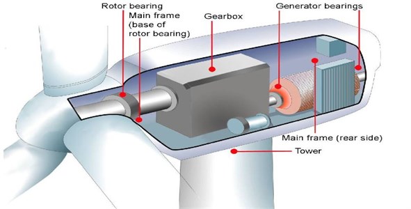
Fig. 1. Components and measuring points with the reference to VDI 3834 part 1 [14]
The testing procedure with reference to the standard [3] is a document, from the point of view of the laboratory management system, that describes in details the methodology of a test. In this case: wind turbine continuous vibration monitoring system. Implementing the requirements of the standard [3] the testing procedure has to be developed, documented and implemented. Therefore, after analysis of the data from the reference materials one can start elaborating the procedure as a document. Usually such a document has a specific, unique graphic design. For the purpose of the paper the authors decided to present it in the form of a description given below.
Creating the document firstly a purpose of the procedure has to be defined. In the case of continuous monitoring of wind turbines it is to ensure proper handling during vibration diagnostics of wind turbine as an object of study. Secondly an object of monitoring has to be defined. In this case wind turbine may be defined as the test object, which consists of rotor and nacelle placed on the tower. The most important part of a wind turbine is the rotor, where wind energy is conversed into mechanical energy. It is mounted on the shaft, which is driven by a generator. Rotor mostly rotates at a speed of 15-20 rpm, whereas typical asynchronous generator produces electricity at a speed of 1500 rpm. Therefore, it is necessary to use a gear box, where rotational speed is increased. Mostly tri-aerofoil rotors are used, made of glass fibre reinforced by polyester. In rotor hub servo-mechanism is placed allowing to adjust inclination angle of blade (stroke). Nacelle must be able to rotate 360 degrees, so it always can be set against the wind. Therefore, the top of the tower engine is installed which, via a gear transmission can be rotated. In power plants of low power, where the mass of the nacelle is relatively small, its setting against the wind is provided by rudder connected to nacelle. The work of the blade adjusting mechanism and directing of wind turbine is managed by the microprocessor system based on inputs (e.g. wind speed and wind direction). In addition, in the nacelle there are placed: transformer, bearings, lubrication systems and brake ensuring rotor’s stop in case of emergency. Another important definition is continuous monitoring. It is responsible for monitoring dynamic state of an object, temperature of constituent components of element in real time (i.e. whole period of operation – test object).
Describing the test conditions it should be mentioned that during the process tools and instruments are used to measure basic dimensions of an object necessary during elaboration of test results, vibration transducers, temperature sensors, the device collecting measurements, remote communication devices. Conditions for an object can be defined as:
a) a unit in operation,
b) the conditions applicable to the operation of wind turbines (wind speed 4-25 m/s).
The monitoring process can be described by the following scheme:
a) mounting the devices defined in point,
b) start-up of the diagnostics system,
c) start of a wind turbine in defined range of speed,
d) monitoring of vibration and temperature (measuring points and their characteristics),
e) assessment is made on the basis of two criteria: design (wind turbine must consist of the following elements: the nacelle, tower, generator, gearbox) and references to the measurement of acceleration and speed measured on the elements of the structure. The measured values are classified into three zones: (1) good: appropriate for perpetual operation, (2) temporarily allowed: probably inappropriate for perpetual operation of the object, it is recommended to determine fault cause, (3) unacceptable: risk of damage,
f) in the case of exceeding temporarily allowed value system starts alarm by sending the information wirelessly laboratory in parallel is run emergency measurement procedure,
g) by emergency measurement is understood registration of vibration’s parameters and temperature at the point of exceeding the alarm and to collect vibration spectrum and save in memory of logger,
h) analysis of data from point g) and on that basis determination of exceedances’ cause and to provide information to the wind turbine’s user,
i) in the case of exceeding unacceptable value system signals an alarm by sending the information wirelessly to the laboratory and the user (in order to take a decision on further object’s operation) in parallel is running emergency measurement procedure,
j) actions similar to those in points g) and h).
Termination criterion of monitoring is defined in the test conditions specified a contract by a customer ordering the test. Moreover, with reference to the zones defined above and associated with them the actions described above the termination of tests may be due to exceeding the critical values and an appropriate decision of wind turbine’s user. Scope of the test results depends on the test conditions specified in a contract. The test report is drawn up in accordance with the appropriate general procedure (provided during implementation of management system). In case of wind turbine’s diagnostic monitoring the following information have to be provided: description of the test object, drawing or photograph of the object, measurement conditions, measured values, ranges of critical data, analysis results, personal details of research staff, date of performed tests.
3. Measurement equipment reliability as a key requirement of accredited monitoring
In the chapter 5 of the standard [3] one can read that many factors determine the correctness and reliability of the tests and/or calibrations performed by a laboratory. These factors include contributions, among others, from equipment, measurement traceability and the handling of test and calibration items.
Discussing the case of continuous vibration monitoring process it is essential to mention that the standard [3] states that all equipment used for tests, including equipment for subsidiary measurements (e.g. for environmental conditions) having a significant effect on the accuracy or validity of the result of the test, calibration or sampling shall be calibrated before being put into service. The laboratory shall have an established programme and procedure for the calibration of its equipment. The procedure for estimating uncertainty. Estimation of the uncertainty is one of the key requirements.
Limitations of the paper regarding its volume does not enable the authors to present complete data on the topic. Shedding light on the problem, in order to introduce the proper proceeding, reliability of temperature measures are about to be mentioned. As they are important for the procedure or the continuous dynamic monitoring process it is obvious that proper equipment has to be used. There are various temperature measurement instruments. The exemplary proceeding on intermediate checks is presented in Table 2. In the first step the visual examination is performed. Next, as it can be seen, a thermometer used for the testing processed should be compered, during intermediate checks, with the reference instrument that was previously calibrated in a calibration laboratory. Comparing the testing instrument to the reference one enables the laboratory personnel to assume that they discuss reliable results of the specific process. In the next step it is essential to calculate measurement errors and measurement uncertainties (depending on the process type A evaluation, type B, combined standard uncertainty or expanded uncertainty can be considered). It has to be emphasized that the processes of intermediate checks and measurement uncertainty calculations have to be performed on the base of documented procedures and/ or instructions.
Table 2Example of the report of intermediate checks for thermometers
Equipment identification: Electronic thermometer 1 | |||||||||
No.: | Date: | Verified by: | |||||||
Data of the reference instrument: Liquid in glass thermometer no. | Code: | ||||||||
I. Visual examination | |||||||||
No remarks | |||||||||
Test results | |||||||||
No. | Temperature of the reference instrument °C | The verified thermometer | Measurement errors | Error limit 3 °C | |||||
Temperature °C | |||||||||
1 | 15,0 | 14,5 | 14,6 | 14,2 | –0,5 | –0,4 | –0,8 | ||
2 | 18,0 | 19,1 | 19,0 | 18,8 | 1,1 | 1,0 | 0,8 | ||
3 | 20,0 | 20,5 | 20,8 | 20,8 | 0,5 | 0,8 | 0,8 | ||
4 | 23,0 | 22,6 | 22,1 | 21,8 | –0,4 | –0,9 | –1,2 | ||
5 | 25,0 | 23,5 | 23,9 | 24,1 | –1,5 | –1,1 | –0,9 | ||
Remarks: | |||||||||
Calculation of measurement uncertainty (with accordance to the proper documented procedure) | |||||||||
0.24 | 0.39 | ||||||||
0.06 | 0.78 | ||||||||
Conclusions: | |||||||||
4. Conclusions
A testing unit can strengthen trust in the monitoring process applying the procedural approach based on the standard [3] and working in conditions of the accreditation. While results of the monitoring process are so important to societies it is essential to invest in organisational and technical tools that enable to increase reliability of test results. In the paper, due to volume limits, only chosen aspects were mentioned. While the procedural approach defines temperature as a one of key parameters it is important to specify the proper handling of measurement items in the area. Intermediate checks are one of methods of proper actions. In order to avoid mistakes the method has to be documented. Consequently, each measurement instrument used during the continuous vibration monitoring process has to be covered with such a proper maintenance.
Details on the test method and measurement equipment were only mentioned in the paper but the standard [3] emphasizes also method validation, accommodation and environmental conditions, sampling as important factors for reliability of tests results so for the complete presentation of the problem more aspects have to be discussed in the future. Finally, human factors (i.e. the experience of authors mentioned in the begging of the paper) are essential for the process.
References
-
Zhai Y., Wang D., Zhang J., Han Y. Research on early fault diagnostic method of wind turbines. Telekomnika, Vol. 11, Issue 5, 2013, p. 2330-2341.
-
http://www.ewea.org/fileadmin/files/library/publications/statistics/EWEA-Annual-Statistics-2014.pdf
-
ISO/IEC 17025 – General Requirements for the Competence of Testing and Calibration Laboratories.
-
Lis Z., Szczutkowski M. Determination of input data for the process of validation of own calculation software for basic material data in static strength tests. Journal of Polish Cimac, Vol. 7, Issue 3, 2012, p. 159-165.
-
Barszcz T. Application of diagnostic algorithms for wind turbines. Diagnostyka, Vol. 2, Issue 50, 2009, p. 7-11.
-
Cotton I. Lightning protection for wind turbine blades and bearings. Wind Energy, Vol. 4, Issue 1, 2001, p. 23-37.
-
Kusiak A., Wenyan L. The prediction and diagnosis of wind turbine fault. Renewable Energy, Vol. 36, Issue 1, 2011, p. 16-23.
-
Yan Y., Osadciw L. A., Benson G., White E. Inverse data transformation for change detection in wind turbine diagnostics. Proceedings of 22nd IEEE Canadian Conference on Electrical and Computer Engineering, Delta St. Johns, Newfoundland and Labrador, Canada, 2009.
-
Ye X., Veeramachaneni K., Yan Y., Osadciw L. A. Unsupervised learning and fusion for failure detection in wind turbines. Proceedings of 12th International Conference on Information Fusion, Seattle, Washington, USA, 2009.
-
http://www.windsystemsmag.com, 2011.
-
Szczutkowski M. Elaboration of the wind turbine constant diagnostic system as a testing procedure in an accredited laboratory – the process approach to writing the draft document. Journal of Polish Cimac, Vol. 7, Issue 3, 2012, p. 321-326.
-
VDI 3834 Part 1 – Measurement and Evaluation of the Mechanical Vibration of Wind Energy Turbines and Their Components – Onshore Wind Energy Turbines with Gears.
-
ISO 10816-1:1995 – Mechanical Vibration – Evaluation of Machine Vibration by Measurements on Non-Rotating Parts – Part 1: General Guidelines.
-
http://www.mmf.de/pdf/an22e-wind_energy_vdi3834-1.pdf, 2015.
About this article

