Abstract
The variants reduce the possibility of hydrate formation in the air coolers wet natural gas. The results of numerical simulation of gas flow at different circuits connecting collectors. We propose innovative solutions to prevent the formation of hydrates.
1. Introduction
On the gas fields are widely used air coolers. They can be installed after the installation of complex gas and a booster compressor station, which compresses the gas before it enters the main gas pipeline. Blocks air coolers used in gas fields consist of 10-16 units. Each unit has three longitudinal heat exchange section with six rows of horizontal finned tubes. In each row of thirty (twenty-nine) tubes arranged in staggered rows. The flow of cold air from the bottom up through the six series created by two fans placed on a foundation under the tubular section.
However, in winter conditions in the cooling process “raw” gas booster compressor station after a first stage of compression in the operational practice there is a number of problems. The bottom row of tubes, as a result of local supercooling gas, there are conditions for hydrate formation. On the inner wall of the heat exchanger tubes there are hydrates and ice overlapping section tubes and the individual tubes are destroyed.
The minimum temperature of the gas supplied to the drying should not be lower than the temperature of hydrate formation, “raw” gas within the most refrigerated heat exchanger tubes at a steady cooling. It may be lower than the temperature of hydrate formation at unsteady cooling, in the case of pre-drying and the inhibitor supply tube inside the lower rows.
To ensure antihydrate conditions of air coolers in winter, you can consider using the following technical solutions:
1) the distribution of the gas flow with increasing flow from top to bottom row of heat transfer tubes while maintaining the average flow rate at the section of the apparatus;
2) inhibitor in the feed zone most likely to appear hydrate (bottom row of pipes);
3) a combined solution of the above two directions.
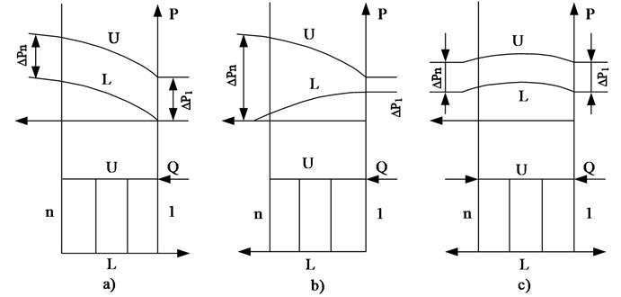
Six rows of vertical heat exchange tubes in each section of the device connected to the distribution and collection chamber, which can be regarded as a collector, respectively for supplying and gas extraction in the process of cooling. We consider several schemes (Fig. 1) connected to the flow collector [1, 2]. From the point of view of efficiency of heat transfer is the preferred scheme of “H” (Fig. 1(c)), gas connection, which allows you to adjust the maximum value flows through the tubes into and out of the reservoir and which is most common. Minimizing the conditions of formation of gas hydrates in the required maximum flow rate of the gas flow in the lower row are not changed when the average flow through the section. This condition may correspond to a scheme of “Z” the gas supply at the cross motion of heat transfer (Fig. 1(b)). The operational units also connected on a “P” (Fig. 1(a)), which is intermediate between the discussed above.
Kind of pressure changes in the input (U) and output (L) reservoirs, shown in Fig. 1, is derived from the one-dimensional assumptions about the nature of the flow. We estimate the features of the two-dimensional nature of the flow in the sewers. To do this, we assume that the number of tubes replaced by an equivalent gas flow flat tube.
Fig. 1Types collector circuits “P” (a), “Z” (b) and “H” (c). 1 ... n - number of branches between the collectors, U – manifold and change the static pressure along the length of the collector, L – collecting manifold and change the static pressure along the length of the collector
We consider equations describing the motion of a viscous heat-conducting gas, excluding the effects of compressibility. Stationary equations of viscous flow are recorded in the two-dimensional formulation:
where – density of the gas; – pressure; , – velocity components on the axis , ; – coefficient of dynamic viscosity; – gas temperature; , , – Prandtl numbers; – the gas constant. The density is determined from the equation of state .
The system of equations of motion is considered in conjunction with the transport equations of the kinetic energy and the dissipation rate . The viscosity is determined by the sum of , where , – coefficients of molecular and turbulent viscosity. There , , , – empirical coefficients and .
At the entrance to the collector at a given initial flow parameters , , , , , where – volumetric flow rate, – radius of the tube. On the walls of the pipes for , , , the adhesion conditions, and for the temperature , where , – thermal conductivity and heat transfer. On the border of the output collector set “soft” conditions, consistent with the vanishing of the second derivatives of all variables.
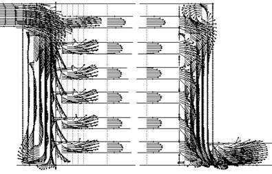
The system of equations is solved using the Patankar’s method SIMPLE [3]. Results are presented in the following figures. Fig. 2 shows the structure of the flow in the collectors, connected by six rows of tubes.
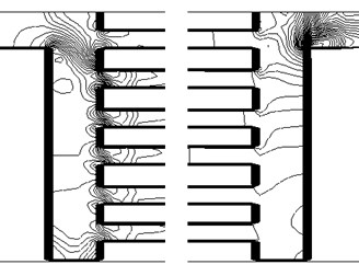
The flow field in the sewers is significantly uneven. There are areas of the reverse flow. This picture also shows the pressure distribution in air coolers (Fig. 3).
Fig. 2The flow field corresponding to the circuit connection “P”
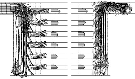
Fig. 3Lines of equal values of pressure (Scheme “P”)
Pressure is uniform just downstream in the tubes. The point of connection pipes in the inlet manifold, there are significant pressure gradients. The behavior of the pressure in the middle sections of the inlet and outlet manifolds shown in Fig. 4.
Fig. 4Change the pressure altitude reservoirs (Scheme “P”)
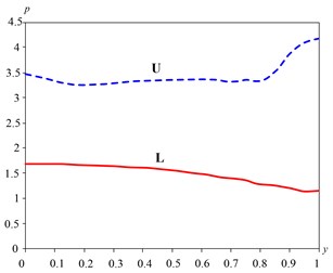
Fig. 5The flow field corresponding to the connection diagram “Z”
The abscissa dimensionless height of the collector, starting from the lower level, the vertical axis – pressure related to the velocity head. Compare with Fig. 1 shows that the pressure change in the outlet manifold has similar appearance. Behavior pressure in the inlet manifold, shown in Fig. 4 is non-monotonic, and not like the one-dimensional distribution. This is due to the significant influence of the connecting pipes and heat exchangers.
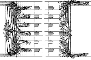
For wiring diagrams “Z” and “H” calculation results are presented in Figs. 5-8.
In the scheme of “Z” the qualitative nature of change in pressure in the output is similar to the one-dimensional manifold (Fig. 1(b)). In the inlet manifold pressure in the direction of the lower pipe is a monotonically increasing only at the bottom (Fig. 6).
Fig. 6Change the pressure altitude reservoirs (Scheme “Z”)
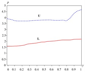
Fig. 7The flow field corresponding to the connection diagram “H”
If we compare Fig. 4 and 6, it is seen that the change in pressure in the inlet manifold schemes “P” “Z” is very similar.
Current collectors, connected in circuit “H” is close to a symmetric (Fig. 7).
Distribution manifold pressure is more uniform (Fig. 8) and is similar to a one-dimensional (Fig. 1(c)).
From these results it follows that the maximum speed achieved in the tubes in the rows of tubes which are closer to the inlet pipe. The maximum speed in the middle of the pipe shown in Fig. 9 for different connections, collectors. The first number () corresponds to the upper row of pipes, and – lower.
Fig. 8The change in pressure adjustment reservoir (scheme “H”)
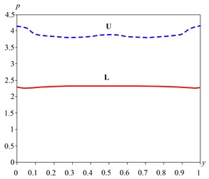
Fig. 9The maximum flow rate the pipes connecting with the different schemes
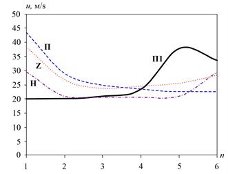
In schemes “P” and “Z” speed in the upper tubes are substantially higher than in the other. Increasing the speed at the bottom of the tube by the scheme “Z” in comparison with the scheme “P” is equal to 5.7 m/s and the speed of 28.2 m/s, which creates less favorable conditions for hydrate formation. The scheme of distribution of streams is useful not only in terms of the possibility of inhibition of the formation of hydrates, but also contributes to rapid evacuation of the lower hydrates germ tube rows by the highest gas flow rate determined by the proposed scheme.
From Fig. 9 that the maximum speed of 43.5 m/s is achieved at the top of the pipe circuit “P”. Therefore, this scheme can be applied in an inverted form, carrying out inlet and outlet of the cooling gas in the lower part of the collector.
Consider submitting a proposal for an inhibitor of the zone most likely to appear hydrate (lower row of pipes). In this case it is necessary to organize the circulation of methanol through the operating unit, handing it to the distribution chamber (collector) and selecting from the collection chamber (collector), accumulate in a special buffer tank, pump and pick up where to apply for recycling.
Positive aspects of the proposed solutions:
– Break ice and hydrates formed not only in the lower heat exchange tubes, but also to collect and which is especially important in the distribution chamber sections of air-cooling;
– The evacuation of water, liquid hydrocarbons, mechanical impurities, etc. of the lower heat exchange tubes, which does not allow developing embryo hydrates and ice;
– Methanol is supplied directly to the zone of hydrate formation in the required amount;
– Create additional thermal resistance to heat flow from the frontal impact of cold air;
– The process may be arranged on a permanent or on an ad hoc (temporary) basis;
– Minimum loss of methanol from the gas.
Forced-feed methanol can be installed in the end of the auxiliary heat exchanger tubes T-shaped pipe inside diameter 2…3 mm. Methanol by ejecting pressure drop in the gas will be supplied from the distribution chamber into the heat exchange tubes. Ejection of the supporting tube it is advisable to arrange at the bottom wall of the heat exchange pipes to the supply amount of methanol was unnecessary.
Fig. 10The flow field, the corresponding connection scheme “P1”
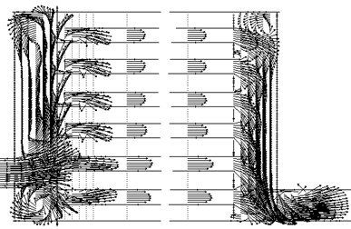
Fig. 11Change pressure adjustment reservoir (Scheme “P1”)
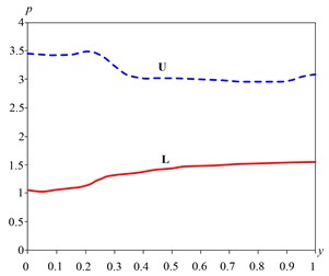
Fig. 12The lines of equal pressure values (Scheme “P1”)
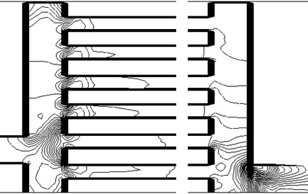
Consider the possibility of organizing supply inhibitor compound in an inverted pattern “P”. To ensure a uniform and stable drop ejection pressure of the gas feed location should be moved from the location of methanol at the bottom of the distribution chamber. This circuit connection “P1” and the flow pattern therein are shown in Fig. 10.
The pressure in the vicinity of the input end of the lower part is a fairly uniform (Fig. 11 and 12).
The maximum pressure difference between inlet and outlet manifolds at the bottom and provides a maximum velocity in the lower tube of 33.5 m/s.
2. Conclusions
The results of numerical simulations show the possibility of reducing the formation of hydrates in air coolers by changing the structural connections, manifolds and flow inhibitor in the zone most likely the formation of hydrates.
In terms of technology revealed the following potential solutions to prevent the formation of hydrates in air coolers: the supply of methanol to the lower number of heat exchange tubes sections and recycling it through the air coolers; distribution of the gas flow with increasing from top to bottom row while maintaining the average flow rate at the section.
References
-
GOST 20 764-79. Air Coolers. Types, Basic Parameters and Dimensions.
-
Molokanov J. K. Processes and Devices Refined. Chemistry, 1980, p. 407.
-
Patankar S. Numerical Methods for Solving Problems of Heat Transfer and Fluid, Dynamics. Energoizdat, 1984, p. 150.
About this article

