Abstract
In actual field testing environments of hydropower unit, unit vibration signals are often contaminated with noise. In order to obtain the real vibration signal, a vibration signal de-noising method of hydropower unit based on adaptive local iterative filtering (ALIF) and approximate entropy is presented. For the proposed method, the ALIF method is used to decompose vibration signal into several stable components. The approximate entropy of each component is calculated. According to a preset threshold value of approximate entropy, the eligible components are retained to achieve the noise cancellation of hydropower unit’s vibration signals. The ALIF-based method and the wavelet denoising method is compared by simulation signal and real signal. The root mean square error (RMSE), partial correlation index and signal to noise ratio (SNR) are used to evaluate the noise reduction ability of two methods. The results show that compared to the classical wavelet denoising method, the noise canceling ability of this proposed method has improved in some extent. It can more effectively suppress the noise of hydropower unit’s vibration signals. The denoised vibration signals are used to synthesize the shaft orbits of hydropower unit. This can effectively identify the rotor shaft orbit graphics and the operation state of hydropower unit.
1. Introduction
The vibration of hydropower unit is an important indicator for measuring the stability of the unit’s operation [1]. The accuracy of the acquired vibration signal of hydropower unit has a direct impact on the precision of the state evaluation of unit. Due to the impact of the uncertainty of the internal structure and external environment of unit, hydropower unit’s vibration signals often contain a lot of random noise. This seriously affects their test accuracy [2, 3]. How to effectively reduce the noise of test signal and improve the test accuracy of the signal, has always been a hot and difficult study for field test of hydropower units.
Wavelet transform [4, 5] has good analysis feature with multi-resolution. It can effectively separate signal at different frequencies and different time. So it has been widely used in reduce noise for vibration signal. However, there are two limitations in using wavelet transform to vibration signal de-noising. (1) Wavelet transform requires pre-selected wavelet basis and decomposition layers. Under the same conditions, the selection of different wavelet bases and decomposition level will have great impact on the de-noising results. This brings a lot of inconvenience for the use of wavelet to the de-noising. (2) Wavelet transform essentially is a band-pass filter. It is more suitable for the decomposition of linear and steady-state signal. For the non-linear and non-stationary vibration signals of hydropower unit, the effect of noise reduction by using wavelet is not particularly desirable. Empirical mode decomposition (EMD) [6, 7] has high frequency resolution and adaptive decomposition characteristics, but there are some defects of model mixing and end effect.
Cicone et al. proposed a new technique, the adaptive local iterative filtering (ALIF) method [8, 9], which uses the iterative filters strategy together with an adaptive and data driven filter length selection to achieve the decomposition. ALIF method with the purpose of designing a local, adaptive and stable iterative filtering method. Approximate entropy [10] is a measure method of complexity for a time series, which is based on marginal probability distributions statistical. The required data length of this method is short. It has strong noise immunity. It can be used to analyze random signals and deterministic signals. Using approximate entropy to quantify the mechanical vibration signal, with the complexity information of it contains, the purpose of feature extraction can be achieved. In this paper, ALIF method and approximate entropy method are used to analyze the vibration signal of hydropower unit. This can reduce the pollution of environmental noise to vibration signals, improve the signal to noise ratio. And the real vibration signal can be separated from the mixed signals with noise.
2. Adaptive local iterative filtering method
The adaptive local iterative filtering (ALIF) method is based on the Iterative filtering (IF) [8, 9] technique. The main differences between the ALIF method and the IF technique are the ALIF method can compute adaptively the filter length and the filters can be chosen from Fokker-Planck equations to compute the moving average of signals. The ALIF method is presented as follows:
Step 1. Given a signal , . Supposing .
Step 2. Assuming .
Step 3. The operator is defined which captures the fluctuation part of as , where the superscript refers to the IMF number. Compute the filter length for
where , , are filters used at step with mask length .
The computation of the filter length given in [11], it is computed as:
where is the total number of sample points of a signal , is the number of its extreme points, is a parameter usually fixed around 1.6, and rounds a positive number to the nearest integer closer to zero.
Step 4. Repeat Step 3. The sifting process stops when the stopping criterion is satisfied.
Step 5. Repeat Step 2 to Step 4.
The sifting process stops when the number of extrema of 2.
Step 6. .
The ALIF method has two iterations: one capturing a single IMF and another producing all the IMFs. The former is called the inner iteration. The latter is called the outer iteration. The updating step of the inner iteration is:
An equivalent formulation of the updating step is used to establish the convergence theorem of the ALIF method. The scaling function can be linear as , cubic as . The is used to change the right-hand side in Eq. (1) as:
So the Eq. (1) can be rewritten as:
where , , is a fixed filter.
A new operator is defined as . The convergence theorem for the inner iteration of ALIF method is:
Let , , be continuous and . Let:
If , , as , Then converges to an IMF.
The convergence theorem for the outer iteration of ALIF method is:
Let , , be continuous and differentiable and let have a finite number of extreme points in any compact interval. So has at most countable extreme points. Let , 1, 2, …, , be the extreme points of . Assume that is strictly monotone in [, ], 1, 2, …, 1. The functions and are defined using as:
The is assumed as a differentiable function with properties described above. The Eq. (2) is used, if the scaling function is separable, i.e. and for every :
Then the number of extreme points of is at most the number of extreme points of if exists.
The detailed introductions of the ALIF method are given in [8, 9].
3. Approximate entropy
Approximate entropy [10] defines the aggregation degree of phase vector in high-dimensional space. The complexity of time series is calculated from a multi-dimensional perspective. It includes the information of time pattern. For the time series of points , the approximate entropy can be obtained through the following steps:
Step 1. The series consists of -dimensional vectors , i.e.:
where 1, 2, …, 1.
Step 2. For each value, the distance between vector and the rest vectors is calculated:
where 1, 2, …, 1.
Step 3. Giving a threshold valve (0), for each value, the number of is counted, and the ratio of this number and the total number of vectors is denoted as:
Step 4. The logarithm of is computed, and their average for all is calculated as follows:
Step 5. Repeats the process of Step 1 to Step 4 for 1, the can be obtained.
Step 6. Finally, the approximate entropy is defined as:
where is a preselected pattern dimension, is the preselected similar tolerance. In actual calculation, usually take 2, (0.1-0.2), where is the standard deviation of time series .
The approximate entropy is used to measure the complexity of the time series. The stable components (which are obtained using ALIF method) are the time series from high to low frequency. So the approximate entropy can be used to quantify these components. This can achieve the extraction of useful information of these components.
4. Vibration signal de-noising of hydropower unit based on ALIF and approximate entropy
Among the symptoms of hydropower unit’s fault presented, the shaft orbits can intuitively reflect the states of the unit’s main shaft, so they are one of the most important methods for the fault diagnosis of hydropower unit. In engineering practice, the collected vibration signal contains a large amount of noise, so the synthesized original shaft orbits have complex shape, are difficult to discern. Therefore, it is urgent need to filter the raw data to purify the complex orbits. This can effectively identify the rotor shaft orbit graphics.
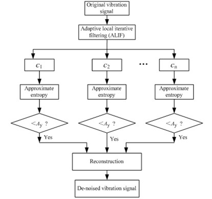
In order to eliminate the noise of vibration signal of hydropower unit, a de-noising method based on ALIF and approximate entropy is presented. This method can achieve the separation of vibration signal and noise. The specific steps of the proposed method are as follows:
(1) The ALIF is used to decompose the vibration signal of hydropower unit into several stable components.
(2) The approximate entropy of each component is calculated. And the threshold of the approximate entropy is determined.
(3) The components whose approximate entropy is less than a given threshold value are reconstructed to complete the de-noising of hydropower unit’s vibration signal.
Fig. 1 is the flow chart for vibration signal de-noising of hydropower unit based on adaptive local iterative filtering (ALIF) and approximate entropy.
Fig. 1Flow chart for vibration signal de-noising
5. Simulation signal analysis
For the comparison of de-noising performance, the wavelet de-noising method and ALIF de-noising method are simultaneously used to analyze simulation signal of hydropower unit’s vibration. For the wavelet de-noising method, firstly appropriate wavelet basis is selected, the original signal with noise is decomposed by using wavelet transform. Then a soft threshold or hard threshold is used to process corresponding wavelet coefficients. This can acquire new compressed wavelet coefficients. Finally, the signal with removing noise can be obtained through the wavelet inverse transform.
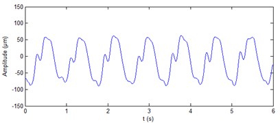
The vibration of hydropower unit is mainly affected by mechanical excitation and hydraulic excitation. The mechanical excitation is mainly intermediate frequency (one times the unit rotational speed, two times unit rotational speed, three times unit rotational speed). The hydraulic excitation is mainly low frequency (0.2 to 0.45 times the unit rotational speed). In this paper, the following expression is used to simulate the vibration signal of hydropower unit’s main shaft at guide bearing, as:
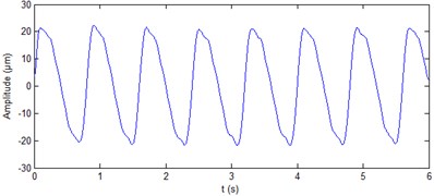
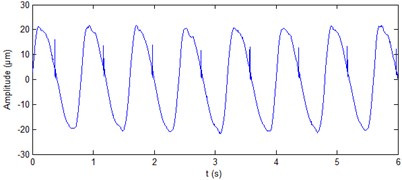
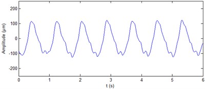
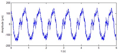
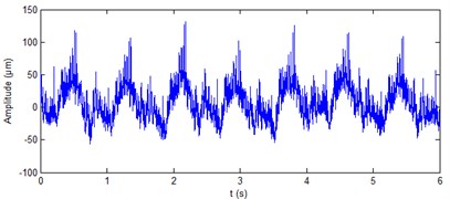
where - are 21 μm, 4.56 μm, 2.56 μm, 1.49 μm, 0.39 μm, 0.31 μm, respectively; - are 1.25 Hz, 2×1.25 Hz, 3×1.25 Hz, 4×1.25 Hz, 0.2×1.25 Hz, 0.3×1.25 Hz, respectively. The sampling frequency is 1000 Hz. The simulation vibration signal of hydropower unit is shown in Fig. 2(a). The signal is added a shock signal whose period is 1.25 Hz, each shock sustained 3 ms. And the signal is also added a Gaussian white noise whose SNR is 20 db. The signal added shock and noise is shown Fig. 2(b). It should be noted that, due to the randomness of the noise, so that the acquired new signal will be different for the same signal is added the noise every time.
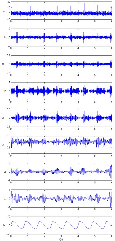
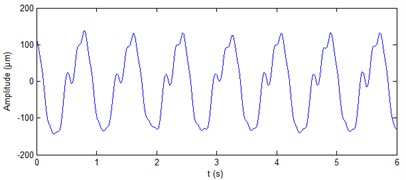
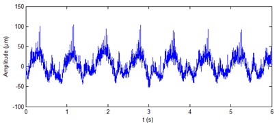
The ALIF is used to decompose the noisy signal into nine components, as shown in Fig. 3. The approximate entropy of these components is computed, the results are shown in Table 1. It can be seen from the table that the approximate entropy of - is significantly greater than the . On the basis of the rule that the approximate entropy threshold is less than 0.4, the can be used as the de-noised signal of hydropower unit vibration. Fig. 4(a) show the results of the de-noising method based on ALIF method.
Fig. 2Simulation signal of hydropower unit vibration
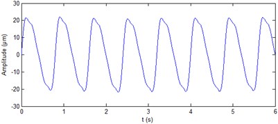
a) Simulation signal
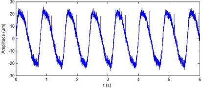
b) Simulation signal with white noise added
Fig. 3ALIF decomposition of the vibration signal
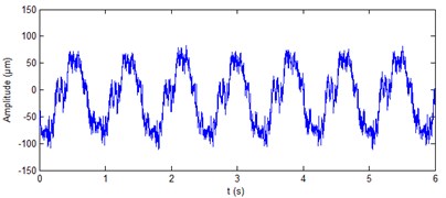
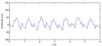
The wavelet transform is widely used in signal de-noising. In this paper, the db4 wavelet is used to process the noisy signal as shown in Fig. 2(b). For purposes of comparison, the decomposition level is also nine layers. The more common “sqtwolog” way is used to as processing threshold. The results by using db4 wavelet are shown in Fig. 4(b). It can be seen from Fig. 4(b) that db4 wavelet is not great for removal of the periodic shock noise.
Table 1Approximate entropy of each component.
2.1878 | 2.0492 | 1.8864 | 0.6515 | 0.6648 | 0.6588 | 0.6128 | 0.5807 | 0.0419 |
Fig. 4Processing results of simulation signals
a) Denoising results with ALIF
b) Denoising results with db4 wavelet
In order to quantitatively compare the denoising performance of ALIF method and wavelet method, the signal to noise ratio (SNR) [2], root mean square error (RMSE) and partial correlation index [12] are introduced as evaluation criteria. They are defined in Eqs. (12)-(14), where is an ideal signal, is the estimated signal of , is the number of samples. The comparison of the de-noising performance of the two methods is shown in Table 2. It can be seen from the table that three indicators of the SNR, the RMSE and the correlation coefficient in the ALIF-based method are better than that in the db4 wavelet method, that is to say that the ALIF-based method has better de-noising performance.
(1) SNR:
(2) RMSE:
(3) Partial correlation index:
6. Case study
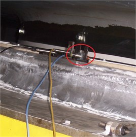
The field test data of a large hydropower unit (its rated rotational speed is 75 rpm, rated power is 700 MW) are selected to verify the de-noising performance of the proposed method. The data include the main shaft vibration signals at generator upper guide bearing of hydropower unit, at generator lower guide bearing of hydropower unit, and at turbine guide bearing of hydropower unit. The test is done aimed at the operation stability of the hydropower unit in whole water head. The measuring points of this test include: the vibration (using velocity-type displacement sensor) of the upper bracket, lower bracket, turbine head cover, stator frame; the vibration (using eddy current displacement sensor) at generator and turbine guide bearings; the pressure pulsation (using pressure sensor) at spiral case inlet, turbine head cover, vaneless region and draft tube outlet. The sampling frequency of the test is 1000 Hz, the sampling points are 6000. Under each water head, after each power generation load adjustment stable, two minutes of data are collected. Test hardware acquisition system is based on NI cDAQ9205 and LabVIEW. The data acquisition board provides 16-bit A/D. Fig. 5 gives the measuring points at generator and turbine guide bearings.
Table 2Denoising performance of two methods
Algorithms | SNR | RMSE | Correlation coefficient |
ALIF method | 32.6777 | 0.3567 | 0.9997 |
db4 wavelet method | 25.5303 | 0.8121 | 0.9987 |
Fig. 5Measuring point at generator and turbine guide bearings
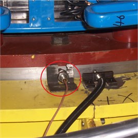
a) Measuring point at generator upper guide bearing
b) Measuring point at generator lower guide bearing
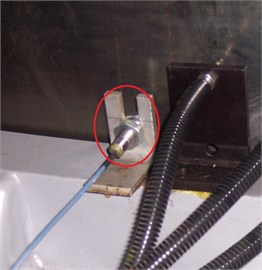
c) Measuring point at turbine guide bearing
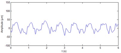
The real signal of shaft vibration ( direction and direction) at generator upper guide bearing of hydropower unit is shown in Fig. 6. It can be seen from the figure that the vibration waveform contains a lot of noise and periodic shocks. The period of shocks is unit rotational speed. The shocks appear attribute to that the unit main shaft is not smooth. The ALIF method is used to decompose the two signals. Nine components are produced respectively for the two signals. The approximate entropy of each component is calculated, the results are shown in Table 3. It can be seen from the table that for the vibration signal in direction, the approximate entropy of is significantly less than the rest. On the basis of the rule of approximate entropy threshold is less than 0.4, the itself is the de-noised signal of shaft vibration ( direction) at generator upper guide bearing of hydropower unit. Fig. 7(a) shows the results of shaft vibration ( direction) ALIF-based denoising method. On the basis of the same rule, the components and of shaft vibration signal ( direction) at generator upper guide bearing are summed to achieve the de-noising of this signal, as shown in Fig. 7(b). It can be seen from the figure that the ALIF method can eliminate a lot of noise and periodic shocks of shaft vibration signal at generator upper guide bearing.
Fig. 6Real signals of shaft vibration signal at generator upper guide bearing of hydropower unit
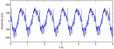
a) direction
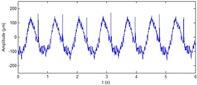
b) direction
Fig. 7De-noised shaft vibration signal at generator upper guide bearing
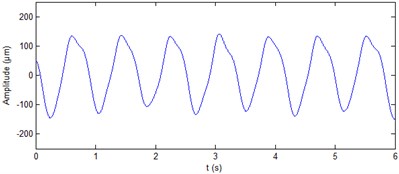
a) direction
b) direction
Table 3Approximate entropy of shaft vibration signal’s components at generator upper guide bearing
direction | 2.0422 | 1.8311 | 0.6597 | 0.6067 | 0.5866 | 0.5467 | 0.5537 | 0.4680 | 0.0430 |
direction | 2.0268 | 1.7429 | 0.6559 | 0.6048 | 0.6031 | 0.5630 | 0.4436 | 0.3448 | 0.0472 |
The real signals of shaft vibration at generator lower guide bearing of hydropower unit and at turbine guide bearing of hydropower unit are shown in Fig. 8 and Fig. 10, respectively. It can be seen from the figure that the four vibration signals contain a lot of noise. The ALIF method is used to decompose the four signals respectively. Eleven components and nine components can be obtained respectively for the two signals at generator lower guide bearing of hydropower unit. Ten components can be obtained respectively for the two signals at turbine guide bearing of hydropower unit. The approximate entropy of each component is calculated. The results are shown in Table 4 and Table 5, respectively. On the basis of the rule of approximate entropy threshold is less than 0.4, the components - of shaft vibration signal ( direction) at generator lower guide bearing are summed to achieve the de-noising of this signal, as shown in Fig. 9(a). The components and of shaft vibration signal ( direction) at generator lower guide bearing are summed to achieve the de-noising of this signal, as shown in Fig. 9(b). The components - of shaft vibration signal ( direction and Y direction) at turbine guide bearing are summed to achieve the de-noising of the two signals respectively, as shown in Fig. 11(a) and 11(b). It can be seen from Fig. 9 and Fig. 11 that the ALIF-based method can well remove a lot of noise in shaft vibration signal at generator lower guide bearing and at turbine guide bearing of hydropower unit.
Table 4Approximate entropy of shaft vibration signal’s components at generator lower guide bearing
direction | 2.0646 | 1.9628 | 1.7617 | 0.6255 | 0.6125 | 0.5985 | 0.5236 | 0.5467 | 0.3391 | 0.1466 | 0.0423 |
direction | 2.1476 | 1.8338 | 0.7098 | 0.6511 | 0.6008 | 0.5896 | 0.4718 | 0.2287 | 0.0408 | – | – |
Table 5Approximate entropy of shaft vibration signal’s components at turbine guide bearing
direction | 2.0048 | 1.9194 | 1.7590 | 0.6736 | 0.6392 | 0.6340 | 0.5905 | 0.3770 | 0.0858 | 0.0378 |
direction | 2.0447 | 1.9621 | 1.8340 | 0.7080 | 0.6497 | 0.6067 | 0.6086 | 0.3904 | 0.1617 | 0.0432 |
Fig. 8Real signals of shaft vibration signal at generator lower guide bearing of hydropower unit
a) direction
b) direction
Fig. 9De-noised shaft vibration signal at generator lower guide bearing
a) direction
b) direction
Fig. 10Real signals of shaft vibration signal at turbine guide bearing of hydropower unit
a) direction
b) direction
Fig. 11De-noised shaft vibration signal at turbine guide bearing
a) direction
b) direction
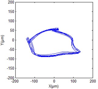
Figs. 12(a), 13(a) and 14(a) give the original shaft orbits of hydropower unit at generator upper guide bearing, generator lower guide bearing and turbine guide bearing. It can be seen from the figures that these shaft orbits contain a lot of noise components, their shapes are chaotic and irregular. It is difficult to directly obtain clear characteristics of shaft orbits and analyze shaft state of hydropower unit. Figs. 12(b), 13(b) and 14(b) are synthesized shaft orbits based on the de-noised Figs. 7, 9 and 11, respectively. It can be seen from the figures that the shaft orbits present obvious oval shapes, can clearly reflect the unit shaft in a normal operating state. This fully shows that the effectiveness of the purification method of shaft orbits of hydropower units based ALIF denoising.
Fig. 12Shaft orbit at generator upper guide bearing of hydropower unit
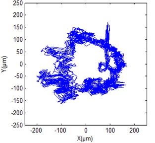
a) True signal
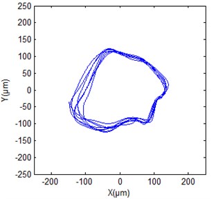
b) De-noised signal
Fig. 13Shaft orbit at generator lower guide bearing of hydropower unit
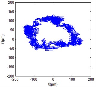
a) True signal
b) De-noised signal
Fig. 14Shaft orbit at turbine guide bearing of hydropower unit
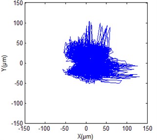
a) True signal
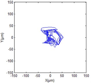
b) De-noised signal
7. Conclusions
ALIF is an adaptive signal processing method, which can decompose complex multi-component AM-FM signal into single component AM-FM signal. The approximate entropy of obtained stable components can reflect the complexity of signal at different scales. This paper proposes a de-noising method of hydropower unit’s vibration signal based on ALIF and approximate entropy. This method uses ALIF method to adaptively decompose complex vibration signal with noise into several relatively stable components. The number of reconstruction components is determined by using the threshold criterion of approximate entropy. This can achieve the de-noising of hydropower unit’s vibration signal. In the noise elimination process, this proposed method can adaptively decompose vibration signal according to their characteristic and calculate the approximate entropy of each component. So the process of de-noising only related to its own characteristic of hydropower unit’s vibration signal, without tedious debugging of parameters and thresholds. The simulation signal of hydropower unit’s vibration is used to compare the denoising performance of the ALIF-based method and wavelet denoising method. The results show that the parameters of SNR, RMSE and correlation coefficients for the ALIF-based method has enhancement in some extent compare with the wavelet denoising method. Real vibration signals of hydropower unit also demonstrate the proposed method’s performance of noise reduction. It can effectively remove the noise to timely and accurately obtain the true state of the unit. After verification of engineering example, the filter purification method of hydropower unit shaft orbit based on ALIF can more accurately extract unit rotor fault feature. The proposed method provides a new tool for rotor system fault diagnosis, has good application prospects.
References
-
Zhang Fei, Pan Luoping, An Xueli Statistical characteristics and maintenance alarm strategy research on stability parameter of hydraulic turbine generator unit. Journal of Hydroelectric Engineering, Vol. 32, Issue 5, 2013, p. 269-272.
-
Su Li, Nan Haipeng, Yu Xiangyang, et al. Application of wavelet denoising of improved threshold function to vibration signal analysis of hydroelectric units. Journal of Hydroelectric Engineering, Vol. 31, Issue 3, 2012, p. 246-251.
-
Wang Jiajun, Pan Luoping, Cao Shuliang Wavelet transforms applied to cavitation noise analysis for hydro-turbine. Journal of Hydroelectric Engineering, 2013, 32(4): 215-220.
-
An Xueli, Jiang Dongxiang, Liu Chao, et al. Wind farm power prediction based on wavelet decomposition and chaotic time series. Expert Systems with Applications, Vol. 38, Issue 9, 2011, p. 11280-11285.
-
Zhang Xin, Feng Naizhang, Wang Yan, et al. Acoustic emission detection of rail defect based on wavelet transform and Shannon entropy. Journal of Sound and Vibration, Vol. 339, 2015, p. 419-432.
-
Luo Xingqi, Xue Yangang, Wang Han Singular data restoration for hydraulic generator fault based on EMD-wavelet analysis. Journal of Hydroelectric Engineering, Vol. 31, Issue 2, 2012, p. 245-250.
-
Wang Han, Luo Xingqi, Xui Yangang, et al. EMD and index energy-based extraction of the draft tube dynamic characteristic of hydraulic turbine. Journal of Hydroelectric Engineering, Vol. 31, Issue 5, 2012, p. 286-291.
-
Cicone A., Liu J., Zhou H. Adaptive local iterative filtering for signal decomposition and instantaneous frequency analysis. Applied and Computational Harmonic Analysis, 2016.
-
Cicone A., Liu J., Zhou H. Adaptive local iterative filtering for signal decomposition. ftp://ftp.math.ucla.edu/pub/camreport/cam13-48.pdf, 2013.
-
An Xueli, Pan Luoping Characteristic parameter degradation prediction of hydropower unit based on radial basis function surface and empirical mode decomposition. Journal of Vibration and Control, 2013.
-
Lin L., Wang Y., Zhou H. Iterative filtering as an alternative algorithm for empirical mode decomposition. Advances in Adaptive Data Analysis, Vol. 1, Issue 4, 2009, p. 543-560.
-
Li Tianyun, Gao Lei, Nie Yonghui, et al. A new adaptive direct-threshold algorithm to partial discharge data processing based on empirical mode decomposition. Proceedings of the CSEE, Vol. 26, Issue 15, 2006, p. 29-34.
Cited by
About this article

This work was supported by the National Natural Science Foundation of China (Grant Numbers 51309258 and 51479076) and the China Institute of Water Resource and Hydropower Research Scientific Specific Research (No. ky1642).
