Abstract
Stabilizing of an inverted pendulum (IP) system is a main problem for researchers working on control theory. Balancing of an inverted pendulum system is one of the major benchmark problems in the control system community. This paper presents optimal tuning of linear quadratic regulator (LQR) controller with The Bees Algorithm (BA) for a linear inverted pendulum. In this paper, a metaheuristic approach which is a nature-inspired search method that mimics the foraging behavior of honey bees is used for design of LQR controller to obtain optimal performance. In LQR controller design, state (Q) and control (R) weighting matrices are basic parameters of LQR which are tuning by designer using trial and error method in usually. The Bees Algorithm optimizes the weighting matrices of the LQR controller so that it can move the cart to a desired position with the minimum change in pendulum’s angle from vertically upright position during the movement. The tuned LQR controller is benchmarked on the linear inverted pendulum experimental device (IP02) that is manufactured by QUANSER Company. After description of the system and The Bees Algorithm, the paper gives the experimental results obtained from the IP02 system to demonstrating the efficiency of the tuning of the LQR controller. Simulation and experimental results are given graphically to show the success of controller. As a result of the paper, the performance of LQR controller shows the effectiveness of The Bees Algorithm which is a diversity method for provide an efficient solution to conventional trial and error design approach.
1. Introduction
The stabilizing of an Inverted Pendulum system is noteworthy an issue in the field of control engineering. It is widely used as design and testing system for control algorithms due to its high degree of instability and nonlinearity. The dynamics of many mechanıcal systems (Two or one wheeled electric vehicle like Segway, self-balancing robots, a booster rocket at takeoff etc.) are similar to the classic control problem of the inverted pendulum. With the recent studies (1) used inverted pendulum to modeling and stability of Humans Standing Posture, it is still an actually topic in science and technology. The experimental verification of simulation studies about improving the balance and of position control the inverted pendulum will increase its effectiveness on realistic applications. The nonlinear and unstable nature of the plant enables an impressive demonstration of the capabilities of feedback systems. For this reason, an inverted pendulum has been one of the main benchmark problems for verifying the performance and effectiveness of a new control method. This is attributed to a lot of engineering applications of the inverted pendulum based system, such as walking and self-balancing robot, in missiles and rockets, jetpacks and transport vehicle like Segway etc.
There are a lot of controller techniques to stabilize an inverted pendulum. Some control types are model-based control approach such as; classical PID, LQR, Robust control, [1-4]. The performance of classical controller depends on selection and tuning method of one or more design parameters which are commonly determined using customary techniques such as trial and error. The other control types are non-model based approach using artificial intelligent methods such as; Neural Network Control, Fuzzy Logic Control and Genetic Algorithms [5].
Selecting weighting matrices of LQR controller is important and difficult [6]. So that, tuning with an optimization algorithm of this matrices are very effective method. In order to improve the controller efficiency and the performance of the designed controller, the optimization of LQR controller parameters has been researched by many researchers. Tan has optimized the LQR controller with improved Particle Swarm Optimization (PSO) and has realized the stability control of the inverted pendulum [7]. Chen has analyzed the relationship between the weight coefficients in weight matrices (Q and R) and the control performance [8]. Wang has adopted an improved Genetic Algorithm (GA) to optimize the LQR parameters and has stabilized the circular-rail double inverted pendulum [9]. As one of the most recent swarm intelligence approaches for real-parameter optimization proposed by Karaboga, The Artificial Bee Colony (ABC) Algorithm is inspired by the intelligent foraging behavior of honeybee swarm and has been demonstrated its high performance over the Genetic Algorithm, Particle Swarm Optimization Algorithm [10]. The predictive Pole-Placement (PPP) algorithm of Gawthrop and Ronco is a continuous-time basis function-based approach. As discussed elsewhere, the number of basic functions is the order of the controlled system leading to a correspondingly small number of optimization parameters [11].
A lot of optimization techniques about the stabilizing control of an inverted pendulum system have been proposed. In this study, unlike purely simulation study, a LQR controller designed and optimized for an inverted pendulum experiment set (Quanser-IP02) using The Bees Algorithm as a diversity method. The obtained experimental results will shape industrial applications and future studies. In order to improve the performance of LQR controller, weighting matrices are tuned with The Bees Algorithm and benchmarked on the experimental setup for stabilize control of the linear inverted pendulum system. The rest of the paper is organized as follows. In Section 2, after introduction, the linear inverted pendulum system is modeled. Section 3 presents the linear inverted pendulum experimental setup. Section 4 describes The Bees Algorithm and optimal tuning of LQR controller method. In Section 5, experimental results and discussions are provided. End of the paper, in Section 6, conclusions are given.
2. Modeling of the linear inverted pendulum
The mathematical model of experimental Inverted Pendulum system (IP02) manufactured by QUANSER Company [12], shown on Fig. 1, consist of cart and pendulum. Cart is of mass () that moves on axis when any force is applied to system and pendulum is of mass (), inertia () and length (2) that rotates on attachment point freely.
Fig. 1Free body diagram of the linear inverted pendulum [12]
![Free body diagram of the linear inverted pendulum [12]](https://static-01.extrica.com/articles/16787/16787-img1.jpg)
The Inverted pendulum system is modeled as Newton’s second law of motion. We obtain notation 1 and 2 when we linearize (for very small pendulum angle). These notations can be represented in state space form:
where:
For the linear inverted pendulum system, the state is defined:
It could be defined and . Substituting state into the equations of motion found where , , and gives:
and:
The and matrices in the equation are therefore:
In the output equation, only the position of the cart and pendulum angle is being measured. Based on this, the and matrices in the output equation are:
State-space representation is a mathematical model of a physical system as a set of input, output and state variables related by first-order differential notations. The state of the system can be represented as a vector within that space. It is briefly shown below notation 5.
Table 1 lists and characterizes the main parameters associated with the linear inverted pendulum. These are used in the mathematical model.
Table 1The linear inverted pendulum system specifications
Symbol | Description | Value | Unit |
Pendulum mass (with T-fitting) | 0.230 | [kg] | |
Pendulum length from pivot to centre of gravity | 0.3302 | [m] | |
Pendulum movement of inertia, about its centre of inertia | 7.88 10-3 | [kg∙m2] | |
Viscous damping coefficient, as seen at pendulum axis | 0.0024 | [N∙m∙s/rad] | |
Gravitational constant on earth | 9.81 | [m/s2] | |
Planetary gearbox gear ratio | 0.90 | ||
Planetary gearbox efficiency | 0.90 | ||
Equivalent viscous damping coefficient | 5.4 | [N∙m∙s/rad] | |
Rotor moment of inertia | 3.90 10-7 | [kg∙m2] | |
Motor pinion radius | 6.35 10-3 | [m] |
3. The experimental setup of inverted pendulum
To obtain controller performance, experiments are conducted using Quanser Linear Motion Plant IP-02 [13]. Experimental setup consists of cart and pendulum. Cart moving on horizontal track driven by DC motor and small gear wheel. Rotating pendulum is actuated by cart. Linear position is measured by cart encoder. The angular disturbance is sensed by pendulum encoder. Schematic diagram of experimental setup of the Linear Inverted Pendulum system is given in Fig. 2.
Fig. 2Schematic diagram of the linear motion plant IP-02
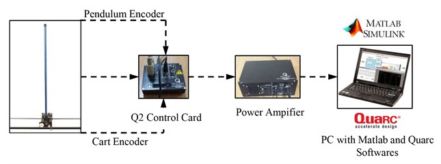
Table 2The linear inverted pendulum system components
ID | Component | ID | Component |
1 | IP Cart | 13 | DC Motor |
2 | Stainless Steel Shaft | 14 | Planetary Gearbox |
3 | Rack | 15 | Linear Bearing |
4 | Cart Position Pinion | 16 | Pendulum Socket |
5 | Cart Motor Pinion | 17 | IP Weight |
6 | Cart Motor Pinion Shaft | 18 | Rack and Plate |
7 | Pendulum Axis | 19 | Rack Set Screw |
8 | IP Cart Encoder | 20 | Track Discontinuity |
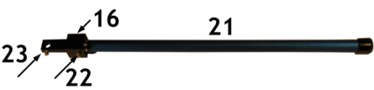
9 | IP Pendulum Encoder | 21 | Pendulum |
10 | IP Cart Encoder Connector | 22 | Pendulum Set Screw |
11 | IP Pendulum Encoder Connector | 23 | Axis Set Screw |
12 | Motor Connector |
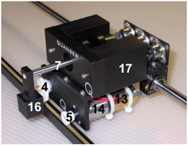
The linear inverted pendulum system components listed in Table 2 below are labeled in Fig. 3(a)-(d). It’s limited motor voltage between +15 V and –15 V and pendulum angle between +1 degree and –1 degree. Encoders are of high resolution of 4096 counts per revolution. To benchmark on setup, it is preferable if the user can use software such as QUARC® or LabVIEW® to read sensor measurements and feed voltages to the motor. The software is built upon Windows7 32 bit operating system to support real time applications.
The system requires an overall space of 2.19 m long by 1.27 m high (0.56 m below table and 0.71 m above) by 0.3 m deep. The system also must be placed on a flat surface and fixed.
Fig. 3The linear motion plant IP-02 component
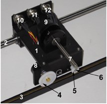
a) Top view
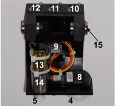
b) Bottom view
c) Front view
d) Pendulum
4. The Bees Algorithm for LQR controller design
In this section presents the introduction of The Bees Algorithm and applying the proposed tuning diversity method to the LQR Controller design for the IP02 system briefly. The Bees Algorithm, which was developed by Pham in 2005 [14], is an optimization algorithm inspired by the natural foraging behavior of honey bees to find the optimal solution. It includes in both the neighborhood search and random search. Fig. 4 demonstrate the flowchart for the proposed algorithm in its simplest form to summarizes the main steps of The Bees Algorithm. As fully described in [14-26], The Bees Algorithm requires a number of parameters to be set namely: number of scout bees (), number of sites selected for exploitation out of n visited sites (), number of top-rated (elite) sites among the m selected sites (), number of bees recruited for the best e sites (), number of bees recruited for the other (-) selected sites (), initial size of each patch (a patch is a region in search space that includes a visited site and its neighborhood) and stopping criterion (iteration number).
Table 3The Bees Algorithm parameters and range of LQR parameters
The Bees Algorithm Parameters | |||||||||||
20 | 10 | 4 | 10 | 7 | 0.001 | 30 | |||||
Optimisation Range of LQR Parameters | |||||||||||
Max. | 200 | 2000 | 2 | 2 | 20 | ||||||
Min. | 0 | 0 | 0 | 0 | 0 | ||||||
Fig. 4Flowchart of the basic the Bees algorithm
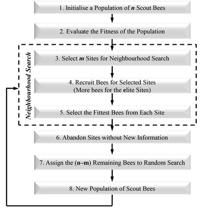
Fig. 5Block diagram of LQR controller tuning
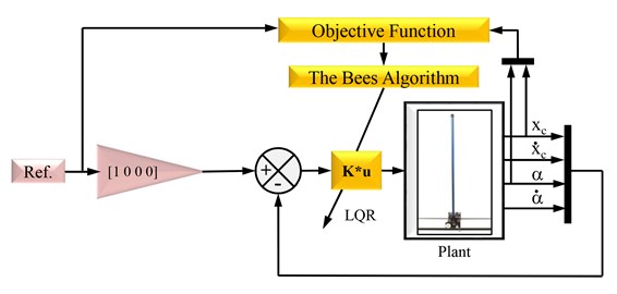
The LQR controller is pre-designed and its parameters and weight matrices are determined by tuned with The Bees algorithm to minimize the objective function which consists of the angle of pendulum step responses and the positioning of cart step responses in time domain.
The idea is to search for the optimal values of the weighting matrices of LQR controller with respect to a determined objective function. The Bees Algorithm and The objective function created according to existed studies [21-25] which defined in Eq. (12):
where is the rise time, is the settling time, is the peak time, is the maximum overshoot, is the steady state error, norm is angle of matrix norm.
LQR control is one of the most effective control algorithm which is concerned with operating a dynamic system at minimum cost, and it’s also commonly used in all field of industry control. The importance and difficulty is selecting the weighting matrices of LQR controller.
For the linear time invariant state space model of the system:
and quadratic cost function:
LQR is a state feedback controller, to stabilize the system and minimize the cost function , where is given by and is obtained by solving the Ricatti notation:
Weighting parameter can be defined as a symmetric positive semi definite matrix and can be selected as a symmetric positive definite matrix:
After calculating , it is applied to system. Full state feedback control was applied to system and results were given in Section 5.
5. Experimental results and discussion
In order to verify the effectiveness of The Bees Algorithm and the optimized LQR controller, experiments have been done. To obtain more efficient LQR controller in order to minimize the objective function , a pre-design LQR controller tuned owing to with excellent search ability of the tuning methods. The Bees Algorithm was programmed in MATLAB and run on an Intel Core2 CPU 2.5 GHz PC with 3.0 GB memory to find a minimum value for the objective function. The optimization procedure carried out successfully and the objective function value corresponding to the optimized solution is 127.4 after 30 iterations in about 15 minutes. The optimization results are [177.8062, 1257.3748, 1.7537, 0.5337] and [0.2574] and the corresponding control gain matrix is [–26.2782, 111.7990, –31.9969, 17.9490]. Control block diagram of the linear inverted pendulum was designed in Simulink and simulated for 25 seconds and controller was benchmarked on experimental setup for same time. Results in graphs show the graphical results obtained by the LQR controller tuned by The Bees Algorithm for angular displacement and angular velocity of pendulum, linear displacement and linear velocity of cart and motor voltage. To verify the effectiveness of the improved The Bees Algorithm and the optimized LQR controller, the controller has benchmarked on the linear inverted pendulum setup.
Fig. 7Pendulum’s angular displacement
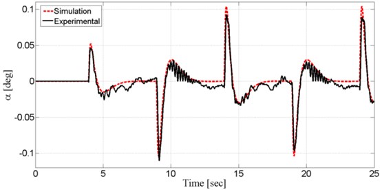
Fig. 7 shows the system output, state pendulum angle (), together with experimental and simulation results. The control signal first responds to the set point change at 4 s. The increasing set point amplitude leads to the change on the pendulum angle. Controller brings pendulum angle () back to upright position “0 rad” in 2.5 s. When modeling the system, some nonlinear cases lead to difference between simulated and actual results. The LQR controller optimised with The Bees Algorithm brought system back to stable state against to sudden change in acceleration.
Fig. 8 shows the system output, pendulum angular velocity (), together with experimental and simulation results.
Fig. 8Pendulum’s angular velocity
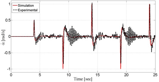
Fig. 9Cart’s linear displacement
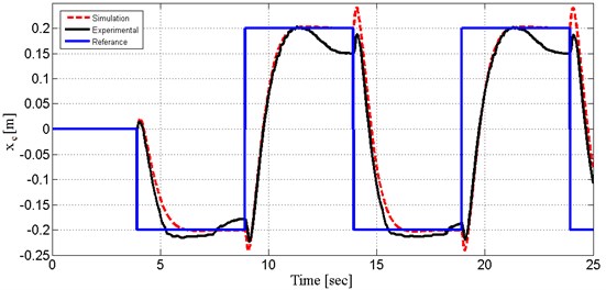
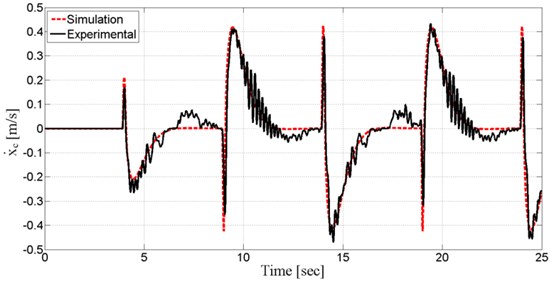
Fig. 10Cart’s linear velocity
The amplitude increased in steps of 0.04 m. Fig. 9 show the system output, cart position (), obtained from both experiment and simulation. As shown on Fig. 10, the step response of optimized LQR controller with The Bees Algorithm has satisfactory tracking performance. Settling time is 2.5 s and overshoot is small enough. Compared with the performance of simulated and experimental results, it is good enough. System output (cart position) followed repeated orbit and simulation and experimental result took place very close.
Fig. 10 show the system output, cart velocity (), obtained from both experiment and simulation. Controller tries to decrease error and response time to minimum so that noise can be tolerated.
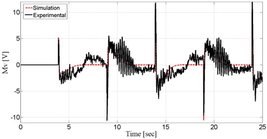
Fig. 11. show the system input (motor voltage), obtained from both experiment and simulation. Motor voltage took shape according to controller criteria prognosticatively.
Fig. 11Motor voltage
6. Conclusions
The tuning of LQR controllers for unstable linear inverted pendulum system with The Bees Algorithm was reported in this paper. In LQR controller design for system, an efficient and alternative solution was investigated to conventional trial and error design methods using The Bees Algorithm which is a nature-inspired search method. The Bees Algorithm which is a tuning method and balancing control of the linear inverted pendulum system is investigated by experimental. The LQR controller obtained by tuning with The Bees Algorithm which is a diversity method for optimization of a controller. The and weight matrices of the LQR controller were tuned using The Bees Algorithm to minimize step response parameters of system in time domain. The aim of optimization is to design a LQR controller to perform an effective control with a minimum error in pendulum angle and cart’s position from desired. Simulation and experimental results of system controlled by the tuned LQR controller are given in figures and were compared with each other to verify the optimization techniques. Results demonstrated that the tuned LQR controller has a sufficient performance to control of the system within controller design criteria. Briefly, the tuning method with using The Bees Algorithm is adequately successful in tuning of a LQR controller. Furthermore, the advantage of the optimization method proposed in this study that it ensures the expected specifications of time domain response of IP02 system in optimization. It can improve performances of the controller by changing The Bees Algorithm parameters, the objective function and the optimization range.
References
-
Chalupa P., Bobál V. Modelling and predictive control of inverted pendulum. 22nd European Conference on Modelling and Simulation, 2008, p. 531-537.
-
Nasir A. N. K., Ahmad M. A., Rahmat M. F. A. Performance comparison between LQR and PID controllers for an inverted pendulum system. International Conference on Power Control and Optimization: Innovation in Power Control for Optimal Industry, Vol. 1052, Issue 1, 2008, p. 124-128.
-
Prasad L. B., Tyagi B., Gupta H. O. Optimal control of nonlinear inverted pendulum dynamical system with disturbance input using PID controller and LQR. Control System. IEEE International Conference on Computing and Engineering, 2011, p. 540-545.
-
Khan A. A., Hussain K. Comparative performance analysis between fuzzy logic controller (FLC) and PID controller for an inverted pendulum system. International Journal of Electrical, Electronics and Computer Systems, Vol. 10, Issue 2, 2012.
-
Noh J. S., Lee G. H., Jung S. Position control of a mobile inverted pendulum system using radial basis function network. International Journal of Control, Automation and Systems, Vol. 8, Issue 1, 2010, p. 157-162.
-
Ogata K. Discrete-Time Control Systems, 2nd Edition. Prentice-Hall, Englewood Cliffs, NJ, 1995, p. 566-633.
-
Wen-long T. A. N. An improved method for rectilinear double inverted pendulum LQR controller parameter optimization. Journal of Chongqing University of Technology (Natural Science), 2012.
-
Chen J., Zhang C. Control of triple inverted pendulum based on LQR coefficients optimization. Computer Engineering and Applications, Vol. 5, Issue 29, 2009, p. 245-248.
-
Haiying W., Hongwen L., Jinlin J., Rui X. LQR control of circular-rail double inverted pendulum based on genetic algorithm. Journal of North University of China, Vol. 2, 2010, p. 132-135.
-
Karaboga D. An Idea Based on Honey Bee Swarm for Numerical Optimization. Technical Report TR06, Computer Engineering Department, Erciyes University, Turkey, 2005.
-
Gawthrop P. J., Ronco E. Predictive pole-placement control with linear models. Automatica, Vol. 38, Issue 3, 2002, p. 421-432.
-
IP02 Linear Inverted Pendulum Experiment for MATLAB / Simulink Users Workbook – Student Version 1.0. QUANSER Inc., 2013.
-
Linear Motion Plant IP-01 and IP-02 User Manual. Document Number 501, Revision 5.0. QUANSER Inc., 2012.
-
Pham D. T., Ghanbarzadeh A., Koc E., Otri S., Rahim S., Zaidi M. The Bees Algorithm Technical Note. Manufacturing Engineering Centre, Cardiff University, UK, 2005
-
Pham D. T., Koç E., Ghanbarzadeh A. Optimisation of the weights of multi-layered perceptrons using The Bees Algorithm. Proceedings of 5th International Symposium on Intelligent Manufacturing Systems, Sakarya, Turkey, 2006, p. 38-46.
-
Pham D. T., Castellani M. The Bees Algorithm: modelling foraging behaviour to solve continuous optimization problems. Proceedings of the Institution of Mechanical Engineers, Part C: Journal of Mechanical Engineering Science, Vol. 223, Issue 12, 2009, p. 2919-2938.
-
Pham D. T., Koç E. Design of a two-dimensional recursive filter using The Bees Algorithm. International Journal of Automation and Computing, Vol. 7, Issue 3, 2010, p. 399-402.
-
Pham D. T., Darwish H. A. Using The Bees Algorithm with Kalman filtering to train an artificial neural network for pattern classification. Proceedings of the Institution of Mechanical Engineers, Part I: Journal of Systems and Control Engineering, Vol. 224, Issue 7, 2010, p. 885-892.
-
Pham D. T., Ghanbarzadeh A., Koc E., Otri S., Rahim S., Zaidi M. The Bees Algorithm – a novel tool for complex optimisation. Proceedings of the 2nd International Virtual Conference on Intelligent Production Machines and Systems, 2006, p. 454.
-
Zhou Z. D., Xie Y. Q., Pham D. T., Kamsani S., Castellani M. Bees Algorithm for multimodal function optimisation. Proceedings of the Institution of Mechanical Engineers, Part C: Journal of Mechanical Engineering Science, 2015.
-
Pham D. T., Castellani M. Benchmarking and comparison of nature-inspired population-based continuous optimization algorithms. Soft Computing – A Fusion of Foundations, Methodologies and Applications, Vol. 18, 2013, p. 871-903.
-
Pham D. T., Castellani M., A comparative study of The Bees Algorithm as a tool for function optimisation. Cogent Engineering, Vol. 2, Issue 1, 2015, p. 1091540.
-
Pham D. T., Koc E., Kalyoncu M., Tınkır M. Hierarchical PID controller design for a flexible link robot manipulator using The Bees Algorithm. Proceedings of 6th International Symposium on Intelligent Manufacturing Systems, Sakarya, Turkey, 2008, p. 757-765.
-
Pham D. T., Kalyoncu M. Optimisation of a fuzzy logic controller for a flexible single-link robot arm using The Bees Algorithm. Proceedings of 7th IEEE International Conference on Industrial Informatics, Cardiff, UK, 2009, p. 475-480.
-
Fahmy A. A., Kalyoncu M., Castellani M. Automatic design of control systems for robot manipulators using The Bees Algorithm. Proceedings of the Institution of Mechanical Engineers, Part I, Journal of Systems and Control Engineering, Vol. 226, Issue 4, 2012, p. 497-508.
-
Sen M. A., Kalyoncu M. Optimisation of a PID controller for an inverted pendulum using The Bees Algorithm. International Conference on Mechatronics and Automation Science, Applied Mechanics and Material Journal, Section: Manufacturing Science and Technology, Paris, France, Vols. 789-790, 2015, p. 1039-1044.
About this article

