Abstract
The tribological characterisation of rail steels has been carried out using rolling-sliding testing device with cylindrical samples with functional geometries. The test can be considered in accordance with the similar one prescribed by the GOST normative. Two steel grade, R260 and K76 Φ have been used for the laboratory characterisation. Wear curves have been carried out and elaborated depending on the in service conditions and wear amounts of the rail. The test is suitable for the comparative wear analysis of rail steels. The experimental results were compared with the curves from scientific and technological literature and with values measured from in service rails to be validated.
1. Introduction
In the last few years there is been a strong development of the railway field in particular with the introduction of the high-speed in the rail transport. This innovation has created a wider intercommunication between the most important developing strategic areas. The comfort for the users, reliability and safety of the facilities in the rail field now, more than in the past, are important to take care. In this frame the maintenance of the rail network is getting more and more important especially because the mechanical stresses, due to the higher train speed, reduce the service life of the track components. Certainly a suitable estimate of the wear rate can be the base on which to build an appropriate maintenance strategy over the entire service life of the rail. Nowadays track tests are carried out to simulate the real work conditions in the rail transport. In this investigation an experimental campaign, dedicated to the tribological characterization of two classes of rail steels (K76Φ and R260 grade), is presented. The main goal is to arrange a test program for the tribological characterization of steels employed in the railway field. In this activity, a surface and metallographic analysis of the tested materials has been also arranged.
2. Materials and methods
Rolling fatigue tests were carried out using the RoR (Ring on Ring) tribometer shown in Fig. 1. In this test bench two cylindrical specimens (the sample to be tested and the counterpart) can be housed for testing in combined rolling and sliding contact. The tribometer can control the radial load from 0 N up to 5000 N. The sample angular speed can be controlled from 100 to 1200 rpm, while the counterpart angular speed can assume values from 100 to 500 rpm. The two axis are able to rotate independently in both directions. The described test bench allows to reproduce testing compliant to the GOST normative [1].
Shows the counterpart, a disc with a radius of 76 mm, which present a circular tooth, 2 mm wide and 2 mm high, on its outer circumference.
This particular geometry was chosen for two main reasons:
• Reduction of the wear track dimensions; high contact pressures (up to some GPa) can be reached at the load conditions within the range of the equipment.
• Constant value of contact pressure during the test, keeping constant the contact area. Other sample geometries can be adopted, e.g., samples with a curved profile instead of a cylindrical outer surface. Previous test campaign shown that such a geometry did not ensure constant pressure during the test due to the tip wear. Furthermore, changes in the contact geometries can induce vibrations during the test, which is particularly detrimental in terms of results reliability.
Fig. 1RoR Tribometer and test configuration
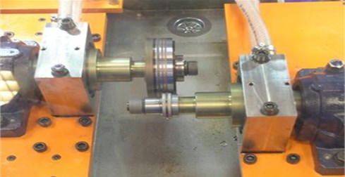
The counter parts were realised in 41CrAlMo7 steel. After machining, they were thermally treated in according to this process: austenitizing to 880 °C for 2 hours, quenching in oil, final tempering at 600-620 °C for 2 hours. After the heat treatment, they were submitted to a deep (0.5 mm depth) nitriding process. The samples used for the tests had a cylindrical geometry, shown were machined from rails in accordance with the cutting scheme reported; in the same picture, the contact area between the sample and the counterpart is indicated. It was chosen to simulate better the real contact condition between the wheel and the rail and to be sure the test was performed in a contact area where hardness is almost constant.
Two typologies of rails materials were investigated: 1) not heat treated rail R260 C-Mn steel grade profile 60E1 (EN13674-1:2011). Hardness: 280 HV. 2) K76Φ steel grade heat strengthened category T1 profile P65 (GOST R 51685-2000). Hardness: 370 HV.
Tests were carried out according to a laboratory operative procedure, optimised on the basis of the GOST standard and previous experiences, which can be summarised as follows:
a) Before the test, samples were ultrasonically cleaned by immersion in an acetone bath (not less than 2 minutes). Then hot air dried.
b) After the sample and the counterpart were installed, the shaft was put in contact and the pressure slowly increased up to reach the requested value. Then, the rotation was activated.
c) Before starting the testing campaign, the equipment was calibrated carrying out a few preliminary pure rolling test using low contact loads, checking the friction coefficient to be in the range 0.1-0.2.
d) Since the tests were carried out in dry conditions, a stream of compressed air was directed on the contact area, to prevent the temperature increasing, which can change the damage phenomenon to be simulated.
e) The tests were periodically interrupted and the depth of the wear track was measured by means of a dial test indicator with a precision of ±0,01 mm. When it was close to 2 mm, i.e., the thickness of the counterpart tooth, the sample was removed, turned up to level of the wear track, and the test procedure was repeated.
The system has a monitoring device of the friction coefficient. In the case of a drastic change of its value, the test is automatically stopped to avoid the surface damage of samples and not to lose the data obtained at the time of the event. A detail of the test configuration is shown in Fig. 2 Starting from the left side of the picture, the counterpart, the sample and the air nozzle can be seen.
Two different tests were performed: a combined rolling sliding test, and a pure rolling test, i.e., a Rolling Contact Fatigue (RCF) test. The introduction of the slippage had other two aims. The first one was to obtain an acceleration level of the test. The other reason was to take into account the real rail wear phenomena, which changes moving from the head (predominant surface fatigue with rolling contact and high loads) towards the gauge head corner (lowest loads and increasing sliding). The tests were carried out up to a cumulative wear track depth of 10 mm, because it is the order of magnitude of the maximum rail wear in service before maintenance. The tests were performed under 1800 N load. The rotating speed of the sample was 450 rpm. The speed of the counterpart was chosen in order to have 2 % of slippage at the contact point in the combined rolling-sliding tests, and pure rolling in the RCF tests. Radial load was chosen taking into account the typical values in rail/wheel contact. Two samples, one for each class of rail steel, have been submitted to a rolling-sliding test for a fixed duration of 200,000 cycles. Such samples were cut, embedded in resin and polished, and their cross section was observed by SEM (Scanning Electron Microscopy), model LEO S430, produced by LEICA, coupled with Energy Dispersive X-ray analyser model Oxford with INCA software. Samples were observed by secondary electrons (SE) for morphology.
Fig. 2Detail of the test configuration
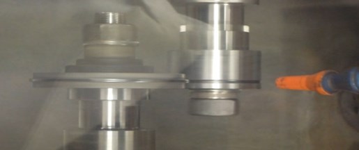
Fig. 3a) Wear curves from laboratory wear tests; b) Wear curves for the rail steels (Wear vs MGT)
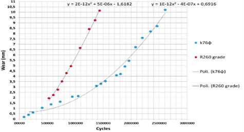
a)
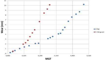
b)
3. Results and discussion
Fig. 3(a) shows the wear curves obtained by the combined rolling-sliding wear tests on the two different steel samples. The values represent the cumulative wear (i.e., the depth of wear track) as a function of rolling-sliding cycles. Fig. 3(b) shows the same data reported vs the accumulated load (Mass Gross Tons – MGT).
Fig. 4 shows the wear of K76Φ samples as a function of accumulative load. Shows the rail steel sample after some wear test phases. Shows a micrograph of the K76Φ steel sample surface in correspondence of the wear track, after 200,000 cycles of rolling-sliding test.
Figure shows a detail of the wear track observed at highest magnitude from micrograph of Fig. 4. The track is characterised by a surface morphology depending on the sliding contact. The slippage, even if very low (2%), induces this surface wave effect. Fig. 4 and Fig. 5 report micrographs of the longitudinal cross section (i.e., in the plane of the rolling-sliding) of the K76Φ steel sample, after 200,000 cycles of rolling-sliding test, at the bottom of the wear track. Microcracks are observed. Microcracks are not perpendicular to the surface but inclined toward the rolling direction (indicated by an arrow).
Fig. 4SEM surface micrograph of K76Φ steel sample
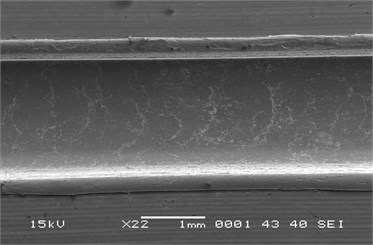
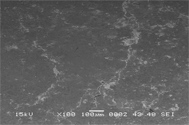
Fig. 5Longitudinal sections: microcracks (K76Φ steel)
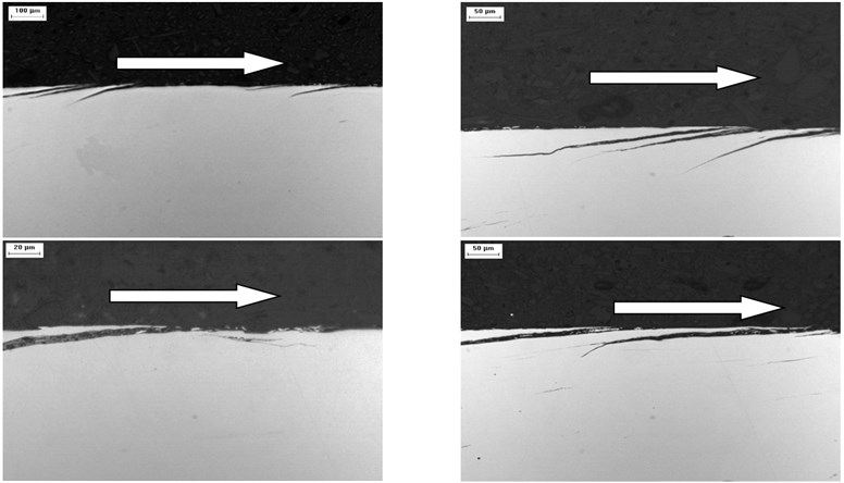
Fig. 5 reports micrographs of the longitudinal section of the R260 steel sample, after 200,000 cycles of rolling-sliding test, at the bottom of the wear track. Also in this case, microcracks were observed.
Fig. 6 show micrographs collected in the transversal cross section of the K76Φ and R260 steel samples, respectively, after 200,000 cycles of rolling-sliding test, at the bottom of the wear track. Microcracks can be observed both in the parallel and orthogonal directions of the contact surface. The damage depth is highest for the R260 grade (almost 100 µm vs 50 µm for the K76Φ steel).
The curve reported in the Figs. 3, 4, and 5 show that the wear of the materials submitted to tests increased linearly for a low number of cycles [2]. Over a critical number of cycles, different for each material and which varies with the test load, the wear increase is not linear anymore. This is coherent with the theory of the rolling-sliding wear phenomena [3]. Literature data about the wear of rails show that the head-check behaviour is linear, at least up to values of a tenth of MGT [7], as shown, for instance, in Fig. 6 [4].
Fig. 6Cross sections carried out on the wear tracks: microcracks (R260 steel)
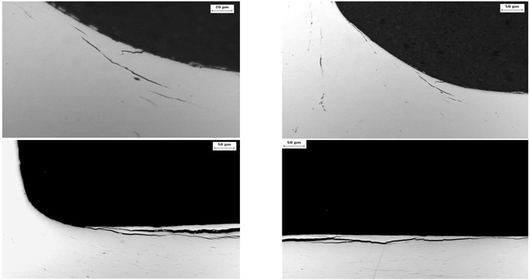
Fig. 7Wear data from “in field” measurements
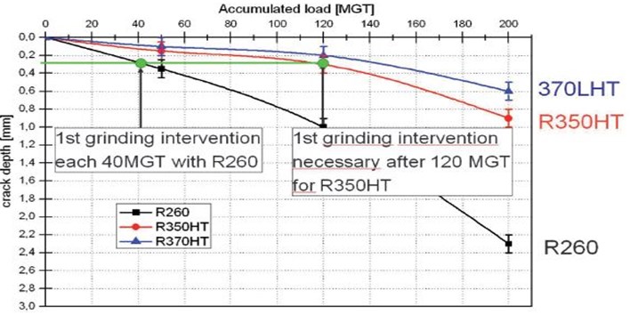
To have a comparison with literature data, referred to the operative rail life, two samples, one for each typology of rail steel, were submitted to a reduced number of rolling-sliding cycles (200,00 stopping the tests when the wear increase of both the samples was still in the linear zone. The analyses of the samples cross sections by SEM, as shown in the Figs. 6, 7 allowed to estimate the cracks depth for the two materials; the ratio between the values measured for K76Φ and R260, respectively, was 1:2. The same ratio can be found analyzing the data reported in Fig. 7. It is possible to conclude that the damage mechanisms observed in the test are similar to the one found in service conditions [5-9]; moreover, the different behavior of the various materials is quantitatively reproduced. The test described in the paper can be therefore used for the tribological characterization of steels, and to carry out a ranking among them. To employ the test for the life cycle assessment of rails produced with different steel typologies, a wide comparative test campaign is needed, in order to have an evaluation of the test methodology on statistical basis.
4. Conclusions
The developed testing methodology can be used for the laboratory quantitative comparison of the tribological properties of rail steels. A specific test procedure has been designed and performed, which can be useful to simulate both wear and rolling contact fatigue. Specifically, two different rail steel were analysed: K76Φ and R260. The cracks depth for the two tested materials was measured after the same number of rolling-sliding cycles; the ratio between the values measured for K76Φ and R260, respectively, was 1:2. The same ratio can be found in the literature for in service rails. To employ the test for the life cycle assessment of rails produced with different steel typologies, a wide comparative test campaign is needed, in order to have an evaluation of the test methodology on statistical basis.
References
-
Tribo-Fatigue Wear-Fatigue Tests Methods. GOST30754-2001.
-
Plu J., Bondeaux S., Boulanger D., Heyder R. Application of fracture mechanics methods to rail design and maintenance. Engineering Fracture Mechanics, Vol. 76, Issue 17, 2009, p. 2602-2611.
-
Wang W., Zhong W., Guo J., Liu Q. Investigation on rolling contact fatigue and wear properties of railway rail. Advanced Tribology, 2010, p. 327-328.
-
Nelias D., Dumont M. L., Champiot F., Vincent Girodin A. Role of inclusions, surface roughness and operating conditions on rolling contact fatigue. Journal of Tribology, Vol. 121, Issue 2, 1999, p. 240-251.
-
Kapoor D. I., Fletcher F. J., Franklin G., Smith L. Rail-Wheel Contact Research. University of New Castle, School of Mechanical and Systems Engineering, Stephenson Building, Claremont Road, Newcastle Upon Tyne, NE1 7RU, UK.
-
UNI EN 13674-1, Railway Applications Track-Rail. 2011.
-
Jonas W. Life prediction of rolling contact fatigue crack initiation. International Journal of Fatigue, Vol. 23, 2001, p. 575-586.
-
Caldwell Rob The Wheel/Rail Interaction – a Primer. National Research Council Canada.
-
Algazy Zhauyt The substantiating of the dynamic parameters of the shaking conveyor mechanism. Vibroengineering Procedia, Vol. 5, 2015, p. 15-20.
-
Joldasbekov Skanderbek, Ibraev Sayat, Zhauyt Algazy, Nurmagambetova Aiman, Imanbaeva Nurbibi Modular synthesis of plane lever six-link mechanism of high class. Middle-East Journal of Scientific Research, Vol. 21, Issue 12, 2014, p. 2339-2345.
-
Dobija Marta, Drewniak Józef, Zawiślak Stanisław, Shingissov Beibit, Algazy Zhauyt Countour graph application in kinematical analysis of crane mechanism. 24th International Conference on Theory of Machines and Mechatronic Systems (IFToMM), Poland, 2014, p. 31-32.
-
Zhauyt A., Kosbolov S., Shingissov B., Alymbetov A., Telesheva A., Karabashev O., Tashkenbayev A. Synthesis of four-link Basic Kinematic Chains [BKC] with spherical pairs for spatial mechanisms. Mediterranean Journal of Social Sciences, Vol. 5, Issue 23, 2014, p. 2627-2637.
-
Kosbolov Serikbay, Zhauyt Algazy, Kosbolov Serikbol Kinematic synthesis of spatial linkages with spherical pairs. Journal of Theoretical and Applied Mechanics, Vol. 54, Issue 1, 2016, p. 75-85.
-
Kosbolov Serikbay, Duisebayeva Kulzada, Zhauyt Algazy, Buzauova Toty Synthesis of spatial lever mechanisms on the basis of the initial kinematic chains SSS pairs. Ponte, Vol. 72, Issue 2, 2016, p. 31-52.
About this article

