Abstract
In order to increase the reliability and safety of a floating nuclear power plant, the research proposes to apply closed-loop cooling systems for floating nuclear power plants’ cooling. Ship hull is proposed to be used as a surface of the heat exchanger, call ship hull heat exchanger. This paper presents detailed study on effect of the ship hull angle on the heat transfer coefficient and measures to improve the heat transfer coefficient. It is concluded that application of gas-liquid flows to the seaside surfaces of ship hull is one of the most effective ways for improving the heat transfer coefficient.
1. Introduction
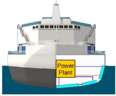
The use of small size nuclear power plants is advisable for regions where there is a lack of electricity supply with their own energy resources or supply of traditional fuels causes a great problem for this area. Furthermore, to develop a nuclear power plant for electricity and heat supply on navigable water areas in the above mentioned problematic regions can be a promising solution [1]. Fig. 1 gives an example of a floating nuclear power plant. Modern industry has the technology for the design and building of nuclear ships and associated equipment. Thus, it is possible to replicate smaller scale standard nuclear power generation units on a the design and building of a floating nuclear power plant are more technologically challenging than that of onshore nuclear power plant where concrete construction is the fundamental structures.
Fig. 1Floating nuclear power plant
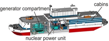
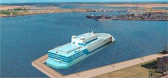
Floating nuclear power plants can be considered as a new model of energy provision. The model is developed based on the nuclear shipbuilding technology. A floating nuclear power plant should be designed for a year-round reliable operation. The floating nuclear power plant considered in this paper is a shore-tied ship designed in accordance with the rules and requirements of the Russian Maritime Register of Shipping. The floating nuclear power plant consists of two KLT-40S nuclear reactors [1]. The demonstration versions of these reactors had been successfully used in the nuclear ice-breakers “Taimyr” and “Vaigach” and the transport ships “Sevmorput”.
The current development has been focused on improvement of the reliability, efficiency and environmental safety of nuclear reactors operating on such ships to ensure the reactors of the floating nuclear power plant have sufficient and effective protection and safety, including passive protection (independent from human intervention or automation). Low-enriched nuclear fuel is used to meet the requirements of International Atomic Energy Agency.
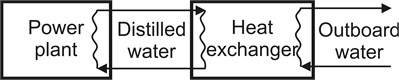
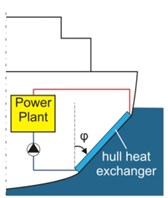
One of the most critical systems serving a floating nuclear power plant is the cooling system. Open-loop cooling systems have been widely applied to ships. As shown in Fig. 2, power plant is cooled with distilled water. In a sea water loop of open-loop cooling system, corrosive sea water often with solids in the sea water causes a reliability degradation of the heat exchanger, thence the power plant. In many cases, clogging of system elements is a significant problem, particularly when operating in contaminated area with shallow water, ice sludge, etc. These operational environment and conditions could lead to a sudden stop of the power plant because of a malfunction of the cooling water supply. Unexpected shut down of power plant results in additional costs for maintenance and repairs. In addition, the open-loop cooling system is harmful in terms of damage to marine and river ecological reserves, since a significant amount of marine species will get into the cooling system with the cooling water and may be exterminated when being discharged overboard [2, 3] and in terms of discharge of radioactive water from of the floating nuclear power plant.
Fig. 2Scheme of an open-loop of power plant
2. Theoretical aspects
Theoretical study of two-phase flow is challenging due to the difficulty in obtaining adequate and accurate mathematical models [4-6]. There are needs to conduct laboratory experiment work to evaluate parameters in the models. The following is governing equations for a free convection system describing the heat transfer, energy conservation, continuity and motion of flow in the boundary [6]:
Additional parameters are required to describe gas-liquid jet flows, such as air bubbles’ motion and their interaction with the surrounding water. Research has been carried out to investigate the interaction of gas-liquid flows with heat transfer surfaces [7-9]. Since a large number of assumptions are taken for the purpose of simplification, there are still uncertainties in the physical phenomena of gas-liquid flow on the surface of ship hull.
Previous thermo-technical analysis of heat transfer processes of SHHE with gas-liquid flows has showed that key influential parameters for the processes are specific air consumption per air manifold, temperature difference between seawater heat transfer surface and outboard water, properties of cooling medium and the slope angle of heat transfer surface. In order to specify the characteristics of the processes, preliminary visual observation and thermal engineering studies were carried out, that have confirmed the crucial impact of these factors.
3. Experimental test rig
Fig. 3 shows the experiment set up for visual investigation of interaction between air bubbles and liquid, where section 4 is the SHHE model, section 1 is transparent container with a dimension of 1.0×0.5×0.1 m.
Fig. 3Experimental setup for visual investigation
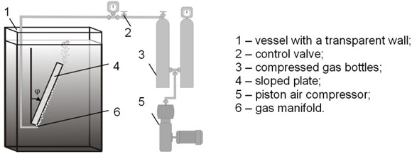
Air is supplied to the bottles (section 3) by the compressor (section 5). Valve (section 2) controls the flow rate of air supplied to manifold (section 6). The container is filled with fresh water doped with aluminum powder and ink. The experiment set up allows the study of movement as a single bubble and the gas-liquid flows along the inclined surface. The definition of specific air consumption used in this study is the air volumetric consumption divided by the length of air manifold.
Fig. 4 presents the experiment model with labyrinth channel (section 2) with a dimension of 0.8 m in height and 0.5 m in width. The thickness of the dividing wall is 5 mm. In order to ensure minimal heat loss, the non-wet sides of the model were insulated. The power unit to be cooled is a 50 kW electric heater as shown in Fig. 8. Fresh water was circulated in the system. Fresh water was heated up to a temperature of 85 °C. The water temperature is set to represent the cooling water temperature of the power plant. The model of SHHE (section 5) was placed inside a tank of 17 m3 (section 4) filled with fresh water. The upper edge of the SHHE model is 0.5 m under the water surface, the lower edge of the SHHE is 1.0 m above the bottom of the tank. This arrangement is to ensure a minimal influence of the tank walls on the circulation of water. The dimensions of the test model were designed based on similarity analysis with the real system as shown in Fig. 5. All parameters of the system were set closely to the operational conditions of the real system. As a result, heat transfer from the SHHE to the outboard water was simulated for the case ship with a closed-loop cooling system in still water.
Fig. 4Ship hull heat exchanger model with labyrinth channels
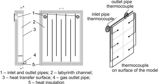
All dimensions of the heat exchanger experimental model were measured. Coolant flow rate was measured by the volumetric method, using a volumetric tank (section 10) with a capacity of 0.04 m3.
The filling time was measured by a stopwatch with an accuracy of 0.05 s. The circulating flow rate was regulated by valve (section 7). The specific air flow rate was regulated by the valve (section 3) on the compressed air line. The measurement of the surface temperature of the SHHE model, the temperature of the circulated fresh water and the temperature in the water tank was performed by thermocouples with a diameter of 0.3 mm thermo electrode. The average temperature of the outer surface of the heat transfer wall (section 5) was measured by six chromel-copel thermocouples placed on the surface of the heat exchanger with an equal space as shown in Fig. 4. The ambient temperature was measured by thermometers with a grade of 0.1 °C. In order to achieve stabilized temperatures of components and the system, the intervals between experimentations were 12-18 hours.
Fig. 5a) Ship shell heat exchanger; b) definition of slope angle; c) heat exchanger surface orientation
a)
b)
c)
4. Results and discussion
It is well known [6] that reducing the thickness or creating a turbulence of the boundary layer improves the efficiency of heat transfer. Therefore, the interaction of air bubbles with the SHHE surface disturbs the surface boundary layers, facilitating and improving heat dissipation. The enhancement in heat transfer achieved by transverse pulsations of rising air bubbles and turbulence of the boundary layer has been observed and measured.
As shown in Fig. 6 a bubble with a diameter of 5 mm at 0° has a rising velocity of 0.33 m/s, and it is 0.2 m/s at – 65º which is more than 1.6 times less that at 0°. This indicates that the air bubble rising velocity is grown up as the angle of the slope is increased. In the meantime, the experiment results also show the rising velocity of air bubbles grows up as the bubble size increases. For example, at – 30° with the bubble diameter of 3 mm, rising velocity is 0.2 m/s, whereas, it is 0.32 m/s when the bubble diameter is 8 mm.
Fig. 6Rising bubble velocity vs. slope angle at different bubble diameters
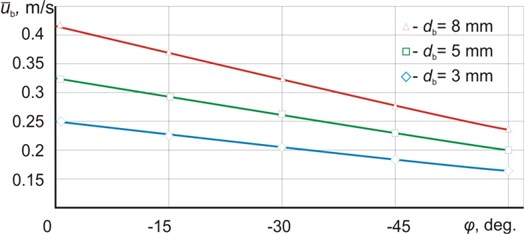
Golovin et al. (1966) concluded that a rising bubble initiates movement of the surrounding water with a velocity of 0.1 to 0.15 m/s less than the one of the bubble. This conclusion is in consistence with the results observed in this experiment.
Fig. 7 shows pictures of the intensity of interaction between the SHHE surface and surrounding water at different bubble diameters when the angle of the SHHE surface slope is set –60°. The development of the bubble’s transverse interaction with surrounding water can be clearly observed as the bubble’s diameter is increased from 3 mm to 10 mm. The interaction disturbs the boundary layer’s flow, leading to an increment in heat transfer coefficient. It is also observed that the moving along surface bubbles produce a scraping effect. The scraping effect also enhances the heat transfer coefficient. Modeling such complex processes relevant through the use of modern information technologies and models [10-14].
Fig. 7Bubble motion along the slope surface
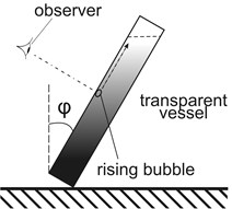
a) Observe direction

b) 3 mm

c) 8 mm

d) 10 mm
5. Conclusions
Floating nuclear power plant is a promising solution to secure energy supply for remote areas in compliance with the performance requirements of classification societies as well as requirements of the International Atomic Energy Agency and concerning the potential radioactive pollution, the use of open-loop cooling systems is environmentally unsafe. The solution proposed in this paper, applying closed-loop cooling system with SHHE for the floating nuclear power plant avoids the using seaside dirty and fouled water and reduces the risk of radioactive emission. The results presented in paper prove that gas-liquid flow improves the performance of the closed-loop cooling system. The maximum heat transfer coefficient for combined free convection and gas-liquid flow can be achieved by setting the surface slope angle of the SHHE at about – 30° with the specific air flow rate at 0.3·10-3-4·10-3 m2/s.
References
-
Petrov E. L. O kommercheskih prioritetah PATES (On commercial priorities of a floating nuclear power plants). Atomic Strategy, Vol. 16, 2005, p. 11-13, (in Russian).
-
Tsipin V. M., Pshenin L. N. Vozvojnosti snijeniya vrednogo vliyaniya raboti energeticheskih ustanovok burovih platform (The possibility of reducing the harmful effects on environment of drilling platform power plants). Proceedings of Science and Engineering Conference on Principles of Design Mobile Offshore Drilling Units, 1980, p. 278-283, (in Russian).
-
Lawrence W. B. Impacts of entrainment and impingement on fish populations. Environmental Science and Policy, Vol. 31, 2013, p. 149-156.
-
Golovin A. M., Levin V. G., Tolmachev V. V. Gydrodinamika puzyrey v jidkosti maloy vyazkosti (Hydrodynamics of bubbles in a low viscosity liquid). Journal of Applied Mechanics and Technical Physics, Vol. 2, 1996, p. 63-71, (in Russian).
-
Fedorovsky K. Y., Vladetsky D. O. Gazozhidkostnaya intensifikatsiya teplootdachi v zamknutyh sistemah ohlazhdeniya energeticheskih ustanovok (Gas-liquid heat transfer intensification in closed-loop cooling systems of power plants). Journal of Sevastopol National University of Nuclear Energy and Industry, Vol. 19, 2006, p. 44-50, (in Russian).
-
Kutateladze S. S. Osnovi Teorii Teploobmena (Fundamentals of the Heat Transfer Theory). Atomizdat, Moscow, 1979, p. 415, (in Russian).
-
Delaur M. C., Chan V. S., Murray D. B. A simultaneous PIV and heat transfer study of bubble interaction with free convection flow. Experimental Thermal and Fluid Science, Vol. 27, 2003, p. 911-926.
-
Kitagawa A., Uchida K., Hagiwara Y. Effects of bubble size on heat transfer enhancement by sub-millimeter bubbles for laminar natural convection along a vertical plate. International Journal of Heat and Fluid Flow, Vol. 30, 2009, p. 778-788.
-
Velichko V. I., Pronin V. A. Heat exchange intensification and power effectiveness increase of convective heating surfaces. MEI, Moscow, 1999.
-
Zhilenkov A., Chernyi S. Investigation performance of marine equipment with specialized information technology. Procedia Engineering, Vol. 100, 2015, p. 1247-1252.
-
Chernyi S., Zhilenkov A. Modeling of complex structures for the ship’s power complex using XILINX system. Transport and Telecommunication, Vol. 16, Issue 1, 2015, p. 73-82.
-
Nyrkov A., Sokolov S., Zhilenkov A., Chernyi S. Complex modeling of power fluctuations stabilization digital control system for parallel operation of gas-diesel generators. IEEE NW Russia Young Researchers in Electrical and Electronic Engineering Conference (EIConRusNW), Saint Petersburg, Russia, 2016, p. 636-640.
-
Ivakhnenko A. G. Modelirovanie Slozhnyih Sistem po Eksperimentalnyim Dannyim (Modeling of Complex Systems on Experimental Data). Radio and Communications, Moscow,1987, p. 116, (in Russian).
-
Nyrkov A., Sokolov S., Zhilenkov A., Chernyi S., Mamunts D. Identification and tracking problems in qualimetry inspections in distributed control systems of drilling platforms. IEEE NW Russia Young Researchers in Electrical and Electronic Engineering Conference (EIConRusNW), Saint Petersburg, Russia, 2016, p. 641-645.
About this article

