Abstract
The article considers the sources of low-potential heat at oil pumping station, estimates the amount of heat of technological processes that is irretrievably lost in the environment from the oil ACD, cooling systems of electric motors and wastewater treatment plants, and also presents possible ways of utilization and useful use of this heat using heat pumps.
1. Introduction
Rational use of fuel and energy resources is today one of the global world problems, the successful solution of which will be of decisive importance for the further development of the world community and the preservation of the environment. The growth of world GDP is largely achieved due to the depletion of natural resources and ecosystems, that is, everything that makes up the so-called natural capital. In 2019, 26.8 % of the global electricity consumption was met by renewable energy sources, together with nuclear energy – 37 %. The share of coal, natural gas and oil in the world electricity production amounted to 63 % or 36.7 %, 23.5 % and 2.8 %, respectively [1].
According to the calculations of the Global Carbon Project, an international research project on monitoring greenhouse gas emissions, in 2021 carbon dioxide emissions worldwide increased by 4.9 % compared to 2020 and amounted to 36.7 billion tons. However, there is reason to hope that global greenhouse gas emissions in 2021 were 5 % less than in 2019. On October 31, 2021, the summit of the G20 countries, whose GDP is about 80 % of the world's, ended in Rome. At the end of the summit, the final declaration was adopted, 66 countries, including the world's leading economies, have recognized the need to achieve global net zero greenhouse gas emissions and carbon neutrality by the middle of the century. They plan to form long-term strategies to achieve zero emissions by 2030 and are going to take measures to limit the growth of global warming at the level of 1.5 °C. A positive example of a significant reduction in greenhouse gas emissions is that across the European Union (EU) emissions have been reduced by 31 % between 1990 and 2020. This is reflecting a shift in public policy in the EU countries aimed at encouraging emissions reduction, as well as increasing investment in energy-saving technologies and renewable energy sources.
2. Heat pump unit
The use of new energy-saving technologies based on the utilization of low-potential secondary energy resources is one of the promising ways to solve the problem of high energy intensity of the fuel and energy complex of Russia. A heat pump (HP) is a device for producing heat using a reverse thermodynamic cycle. This is a device for transfer-ring heat energy from a low-temperature heat sensor to a high-temperature heat receiver, the process is carried out with the expenditure of energy on the compressor drive. The schematic diagram of the operation of the most widespread steam compression heat pump unit can be described as follows (Fig. 1).
Currently, there are more than 30 million heat pumps of various capacities operating in the world – from 5 kW to tens of MW. In the US, more than 30 % of residential buildings are equipped with HP, which are combined heating and air conditioning systems. In Sweden, more than a hundred heat pumps with a capacity of 5 to 80 MW have been put into operation in recent years. In Japan, 3 million HP are sold annually, and in the USA – 1 million [2]. Heat pumps are included in the “List of objects and technologies of high energy efficiency”, approved by the Decree of the Government of the Russian Federation No. 600 dated June 17, 2015. In addition, they are singled out as one of the priority areas of scientific and technological progress in the energy sector in the direction “Heat Supply” in the Energy Strategy of Russia for the period up to 2035.
Fig. 1The schematic diagram of a steam compression heat pump
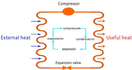
In an external heat exchanger (evaporator), thermal energy from the environment outside the building or from another available heat source is transferred to the working fluid of the HPU – a refrigerant with a low boiling point circulating through the internal circuit. The refrigerant is heated, evaporated and sent to the compressor. The compressor compresses the gaseous refrigerant, while its temperature increases. Further, the com-pressed refrigerant passes through an internal heat exchanger (condenser), in which, condensing, it gives off heat to the consumer system (direct heating of air, water or heat carrier of the heating system).
Then the refrigerant passes through a throttling valve that reduces pressure, which is accompanied by a decrease in temperature and final condensation of the gas-liquid medium, and the cycle repeats (Fig. 2).
Fig. 2The principle of operation of the heat pump: 1 – evaporator; 2 – compressor; 3 – electric drive; 4 – capacitor; 5 – expansion machine (expander)
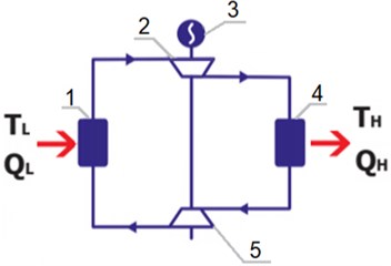
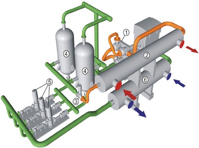
Fig. 3 shows the layout of a CO2 heat pump.
A heat pump or HP does not formally generate thermal energy, but it makes it possible to usefully use the low-temperature thermal energy of the soil, air, water, domestic wastewater, waste heat from industrial enterprises and much more. In general, the most promising low-potential sources for the central part of Russia are the heat of natural water sources.
The sources of low-potential heat can be:
– air exhausted from the room (15-25 ℃);
– lake and river water (0-10 ℃);
– groundwater (more than 10 ℃);
– surface soil (0-10 ℃) and soil with a depth of more than 20 m.
Fig. 3The layout of a CO2 heat pump: 1 – turbocharger; 2 – water heater; 3 – control valve; 4 – liquid separator; 5 – pump for CO2 circulation; 6 – water cooler
The most characteristic temperature level for an external heat exchanger in the mode of using a steam compression in a heat supply system from minus 5 °С to 15 °С, for the internal heat exchanger from 35 °С to 60 °С, which makes it possible to provide heating and hot water supply for most of the heating period. At the same time, if we take the received useful thermal power as 100 %, then the share of the consumed electricity will be 20-30 %. Thus, the energy efficiency coefficient, equal to the ratio of the received useful thermal power to the consumed electricity for the compressor drive, ranges from 3.3 to 4.
Table 1 [3] shows the comparative characteristics of the environmental efficiency of the heat pump unit at the temperature of the low-potential heat source 8°C and tradi-tional organic fuel boilers with a capacity of 1 Gcal / h and specific fuel consumption of 0.3 kg of fuel equivalent / kWh. The use of a heat pump reduces greenhouse gas emissions by 47 % from 1743 to 922.5 tons / year.
Table 1Comparative characteristics of the environmental efficiency of heating systems by greenhouse gas emissions
Parameter | Traditional furnace room | Heat pump | |
Efficiency, % | 65 | 80 | – |
Conversion coefficient, | – | – | 3 ( 8 °С) |
Annual fuel consumption, t/year | Directly at the consumer | At remote thermal power stations | |
Coal | Fuel oil | Coal | |
586.3 | 351.6 | 453.1 | |
Total harmful emissions (NOx, S, CO), in places of heat energy production, t/year | 16.3 | 10 | – |
Total harmful emissions (NOx, S, CO), in places of electric power generation, t/year | – | – | 8.63 |
Greenhouse gas emissions (CO2), t/year | 1743 | 1029.8 | 922.5 |
3. Low-potential secondary energy resources at oil pumping station and their utilization
Let's consider the possibility of introducing a heat pump unit at the oil pumping station for the utilization of secondary energy resources. Technological sources of low-potential heat at an oil pumping station are:
– waste heat of wastewater;
– thermal energy of the oil supply system of main pumping units;
– thermal energy of the cooling system of electric motors.
The required maximum thermal power to provide a typical average oil pumping station is about 640 kW, and electric power is about 3000 kW [4]. About 80 kW is needed to heat the building with the main pumping area 60 × 12 = 720 m2.
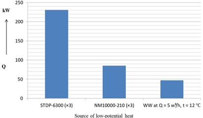
According to the calculations made, the oil supply system of three operating pumping units NM 10000-210 emits 85 kW of low-potential energy into the environment through air cooling devices (ACD), the circulating water supply system for cooling STDP-6300 electric motors – 231 kW (table 2 [5]). Thus, during the operation of three main pumping units (MPU), the heat emitted into the atmosphere from the auxiliary systems is 85 + 231 = 316 kW.
Table 2Technical data on the operation of air coolers of synchronous electric motors
Type of engine | Air cooler type | Discharged losses, kW | Water consumption, m3/h | Air consumption, m3/s | Temperature of the water entering the cooler, °C, no more |
STDP-1600-2U4 | VB-36 | 32 | 20 | 1,0 | 30 |
STDP-2000-2U4 | |||||
STDP-5000-2U4 | VB-70 | 61,3 | 28 | 2,0 | |
STDP-6300-2U4 | 77 | 34 | 2,5 |
Waste water after a treatment plant with a design flow rate of 5 m3/h or 1.39 l/s at a temperature of 12 °C (specific enthalpy is 50.5 kJ/kg) has enthalpy 50.5 · 1.39 = = 70.1 kJ/s or 70.1 kW. In winter, the average temperature of reservoirs and rivers is 4 °C, while the specific enthalpy of water is 16.9 kJ/kg. The amount of low-potential heat that is lost with wastewater is equal to 1.39 (50.5 – 16.9) = 47 kW.
It can be concluded that low-potential energy in the amount of 316 + 47 = = 363 kW is lost to the environment from one main pumping station and a wastewater treatment plant (Fig. 4).
Fig. 4The amount of low-potential heat by type of source
As an example, the heat consumption for maintaining a temperature of 25 °C for oil with a viscosity of 38 mm2/s in RVSP-20000 at an air temperature in the area where the tank is installed during storage is minus 35 °C is 73702 kCal/h or 86 kW.
Thus, low-potential energy, which is irretrievably lost in the environment from air cooling devices, the cooling systems of electric motors and the wastewater treatment plant, it is enough to maintain an oil temperature of 25 °C in winter in RVSP-20000 in the amount of / 363 / 86 = 4 pcs. at 100 % use of these secondary energy resources.
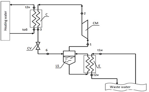
Fig. 5 shows a schematic diagram for the utilization of waste water heat using the heat pump.
The cost of heat pump units of ZAO “Energia” (Energia, CJSC) and their installation is approximately from $150 to $200 per 1 kW of thermal power, depending on the source of low-grade heat. The service life of heat pumps before capital repairs is 45,000-60,000 hours or 10-15 heating seasons, and the payback period doesn’t exceed 2–3 years [6].
Block-modular furnace rooms at the oil pumping stations of PAO “Transneft” (Transneft, PJSC) have a capacity of 4 to 10 MW, they include from 2 to 5 water-heating units (heating plant) UVT-2 manufactured by “Transneftemash”. The heating capacity of the NT-1000 heat pump is 1 MW, which is half the power of the UWT-2 boiler (2 MW). At the same time, the NT-1000 heat pump consumes 300 kW of electric power to drive a screw compressor, and the oil consumption during bo furnace room operation is 112 kg/h or 2.7 tons per day.
Fig. 5A schematic diagram of a single-stage heat pump unit for waste water heat utilization: E – evaporator; LS – liquid separator; СM – compressor; C – capacitor; CV – control valve
The weighted average tariff for oil pumping stations for 2020 was $0.05 for 1 kWh. For a day, a compressor with a capacity of 300 kW as part of a heat pump consumes 300·24 = 7200 kW·h, this will cost the company 7200·0.05 = $360 per day. One ton of oil contains approximately 6.3 barrels, at a market price of $100 per barrel of oil, the total cost of one ton will be 6.3·100 = $630. Let’s take the scenario at a cost of $50 per barrel, then 1 ton of oil will cost $315, and the 1.35 tons of oil consumed by the boiler per day, while saving 50 % of the fuel burned for water heating, will cost 315·1.35 = $425.3.
At the cost of TNU, including installation and maintenance, amounting to about 143 thousand dollars, the heating period in the central regions Russia, equal to 210 days, and the daily savings 425.3 – 360 = $65.3, the annual savings is equal to = 65.3 · 210 = $13700, the payback period will be / 143 / 13.7 = 10.4 years.
Fig. 6The value of the payback period of the heat pump depending on the cost of a barrel of oil and the dollar exchange rate
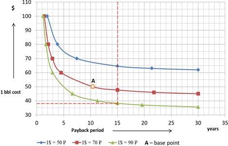
Thus, the payback period of the heat pump is 10,4 years with a service life before overhaul of 15 years and the total service life of the installation at the 30 years. The payback period of a heat pump is determined not only by the cost of one barrel of oil, but also by the exchange rate of the ruble to the dollar. During the calculations, it was found that the payback period takes values from 1.2 to 15 years at an optimal price of more than $ 38 per barrel of oil and is equal to 10.4 years at a rate of $ 1 = 70 rubles, the price per barrel is $ 50 (Fig. 6).
4. Conclusions
1) In general, a heat pump is a fairly environmentally friendly and economical device for utilizing low-potential secondary energy resources and reducing greenhouse gas emissions. The paper considers the possibility of using a heat pump at an oil pumping station, identified the sources and amount of low-grade heat, proposed methods for the beneficial use of this heat.
2) Oil supply systems for three pumping units and circulating water supply for electric motors, as well as a wastewater treatment plant, in total emit about 363 kW of low-grade energy.
3) The NT-1000 heat pump with a heating capacity of 1 MW is capable of saving 50 % of the fuel burned during the operation of the UVT-2 hot water heating plant with a capacity of 2 MW. With the combined use of the heat pump and the furnace room, the payback period of the heat pump will be 10.4 years.
References
-
“World gross electricity production, by source, 2019 – Charts – Data and Statistics.”. https://www.iea.org/data-and-statistics/charts/world-gross-electricity-production by-source-2019
-
E. Gasho, Heat Pumps in Modern Industry and Municipal Infrastructure. (in Russian), Moscow, Russia: Publishing House Pero, 2016.
-
I. Krakhmalin, “Heat pumps in the heat supply system,” (in Russian), Heat Supply News, Vol. 7, 2007.
-
K. Akhmadullin, “Energy-saving technologies of pipeline transportation of petroleum products,” (in Russian), Ph.D. Thesis, Ufa University, 2005.
-
“STMP operating instruction.” http://www.nov-electro.com/2012/instrukciya-po-expluatacii-stdp
-
P. Trubaev, Heat Pumps. (in Russian), Belgorod, Russia: Publishing House of V.G. Shukhov BSTU, 2010.
About this article

