Abstract
The vibration and noise of brakes have always been prevalent and difficult problems in the automobile industry and its related academic circle. The current study mainly focuses on the groan of the drum brake with a foldable cam lever actuation device strainer. The groan of the limit cycle generated by friction reappears after building its model in the ADAMS. Accordingly, a rigid flexible coupling model with a multi-layer friction plate is built. A simulation analysis shows that the model exhibits good braking stability and can reduce the amplitude of a brake groan through a comparison of the vibration characteristics of the drum brake and foldable cam lever with a conventional cam. A virtual prototyping analysis method for the dynamics characteristics of the foldable cam lever brake is also presented.
1. Introduction
Drum brakes are widely used in commercial vehicles because of their considerable braking torsion and low cost. These brakes are also used in the rear brake of passenger vehicles. The friction vibration and noise of brakes, which are prominent and difficult problems in the automobile industry and its related academic circle, have only been recently addressed. Three main methods are currently used to explain the vibration and noise of brakes. The first method was presented by Mills [1], who stated that the vibration and noise of brakes were generated by the friction coefficient that were changed with slide velocity. The second method was presented by Spurr [2], who established the sprag-slip model to explain the brake squeal of a disc brake. The third method was presented by North [3], who acknowledged that self-excited vibration caused by friction would generate the vibration and noise of a brake under a constant friction coefficient. The friction vibration and noise of a brake can be classified based on its vibration frequency into brake moan and groan (vibration frequency is lower than 1 kHz) and brake squeal (vibration frequency is higher than 1 kHz). The auto industry and academia have been unable to identify the mechanism of brake chatter. These institutions have focused only on brake wobble and brake scream but directed less attention towards brake judder. Control methods have yet to be established because research results remain insufficient. The Dedicated Panel Discussion on brake vibration and noise was set up to research brake chatter, brake scream and other technical problems in the Annual Brake Conference of the American SAE, Annual Brake Conference of the European FISITA and Annual Brake Conference of the Chinese Automotive Engineering Society. Many studies have shown that stick–slip vibration is the driving source of brake chatter. Bowden [4] and Morgan [5] performed experiments on the stick-slip vibration of a dry friction oscillator. Two researchers shared the idea that the necessary condition for a brake to vibrate was the negative correlation between friction and velocity. Nosrati and Farshidianfar [6] established a single degree-of-freedom (DOF) model for a brake system; they studied the pure-slip and stick-slip vibrations of the system by using an analytical method and numerical simulation method independently. They also researched on the effect of the friction coefficient on the amplitude of the limit cycle. Ashley and Nong [7, 8] studied the stick–slip vibration under different driving states by establishing a clamp and plate model for a brake system. Awrejcewicz [9] created a nonlinear model with two DOFs, researched the instability of the system using the numerical simulation method and found that the chatter of a vehicle was generated by the stick-slip and chaos of the system using time domain and phase diagrams. Daogao Wei [10] created a model for a brake system with DOFs and found three limit cycle oscillation phenomena over a range of certain braking speeds with specific set of parameters. Mohamed [11], who worked for the American Allied Signal Company, reported that brake chatter was generated by stick-slip vibration and found the stick-slip limit cycle by plotting the phase diagram of velocity and displacement. This researcher also presented the relation between the amplitude of limit cycle vibration and parameters of a brake system by Zhou Minggang [12]. Xu [13] of the TRW Company analyzed creepy groan using the multi-body dynamics method. The stick-slip vibration of brake chatter reappeared using the virtual prototyping model of ADAMS. However, the reappearance of the slide-slip vibration of a drum brake is rarely reported. Moreover, the self-vibration of the new type of drum brake presented in this study has not yet been reported. Accordingly, a model is built in the ADAMS based on the drum brake with a foldable cam lever actuation device strainer presented in [14], and the groan of a limit cycle is found. Moreover, the groan of this foldable cam lever actuation device drum brake with a multi-layer friction plate is researched. This study can provide a virtual prototyping analysis method for reducing the chatter and noise of a drum brake.
The new ideas and innovations presented in this study are as follows.
1) After referring to the existing literature, an exploratory research is conducted on a new drum brake with a foldable cam lever actuation device in terms of its nonlinear vibration characteristics, reappearance and self-vibration phenomenon based on an ADAMS virtual prototype model under braking condition. The simulation analysis of the self-excited vibration characteristics of the brake with a multi-layer lining provides a theoretical basis for the next step in vibration suppression.
2) Previous research methods used on the self-excited vibration of an automobile brake system under braking conditions mainly rely on the qualitative and quantitative calculations and analyses of self-excited vibration characteristics through a mathematical model for a system. Compared with a mathematical model, the ADAMS virtual prototype model can more accurately reproduce the vibration characteristics of a brake system.
2. Establishment of the models for drum brake
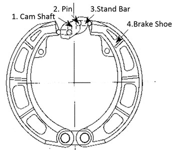
Firstly, the structure of the new drum brake is introduced. The brake shoes are pushed by foldable levers rather than by the cam itself. Two pins (2) are fixed at the cam (1). These pins (2) connect the brake shoes to two stand bars (3). When torsion is exerted on the cam (1), two pins (2) will push the stand bars (3) that are connected to them. Then, the stand bars (3) will push the brake shoes (4), which will connect with the brake drum. Fig. 1 shows that the brake does not actuate. Fig. 2 shows that the brake shoes are open.
Fig. 1New brake shoes are closed
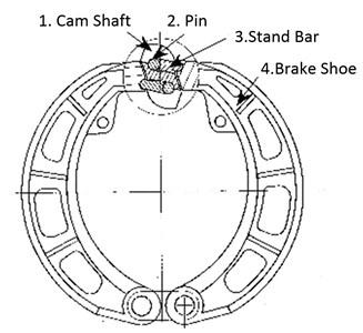
Fig. 2New brake shoes are open
The solid model for this new brake is built in the INVENTOR and simplified as follows. The positioning and limiting parts of the actuator are omitted. The effects of the process hole and reinforcement are neglected. The support pins and bushes are omitted because a fixed constraint will be exerted in the ADAMS. The spring part is omitted because a constraint force is exerted. The chamfered and rounded portions of the parts are neglected. Finally, the brake assembly model includes a brake bottom plate, a supporting platform for the brake shoes, the brake shoes, a friction plate for the brake shoes, an axle sleeve for the cam shaft, the cam shaft, stand bars and brake drum.
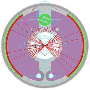
The model is imported into the ADAMS, where each part is renamed, and the materials of all the parts are set. The kinetic pairs of the parts are exerted. The brake bottom plate and ground are fixed together. The supporting platform and brake bottom plate are also fixed together. The constraint between the brake shoes and supporting platforms is a rotating pair. The friction plates and brake shoes are fixed together. The axle sleeve of the cam shaft and the bottom brake plate are also fixed together. The constraints between the cam shaft and its axle sleeve, between the cam shaft and stand bars, between the brake shoes and stand bars and between the brake drum and brake bottom plate are rotating pairs. The model for the contact force between the brake drum and friction plates is a type of impact model in the ADAMS. The force exponent is 2.0, the penetration depth is 0.15 mm, the static friction coefficient is 0.5, the dynamic friction coefficient is 0.3, the stick translation velocity is 2000 mm/s and the dynamic friction translation velocity is 3000 mm/s. The torsion exerted on the cam is 190 N·m. The model established in ADAMS is shown in Fig. 3.
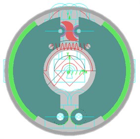
To compare the performances of the old and new brakes, a model for the old one is also built in the INVENTOR and imported to the ADAMS. The modeling process is nearly the same as for the new one except for the difference in the kinematic pair introduced by the structure. The virtual prototype model of the old drum brake in the ADAMS is shown in Fig. 4.
Fig. 3Foldable cam lever brake model in ADAMS
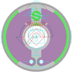
Fig. 4Old cam drum brake model with constraints and force in ADAMS
3. Comparison of vibration performance between foldable cam lever brake and drum brake
When the forced vibration of two types brakes is studied, the sine torque shown in Figs. 5(a) and 5(b) is exerted on the drum brake, which has the amplitude of 5200 N·m, frequency of 1 Hz and initial phase of 0. The simulation time is 2 s. The simulation results are shown in Figs. 5(c) to 5(f).
The comparison of (c), (e) and (d), (f) in Fig. 5 shows that the vibration frequency of the peak value for the old drum brake is approximately 250 Hz, but is approximately 450 Hz for the foldable cam lever brake. The new brake system has higher vibration frequency than the old one; hence, this system can be used as a method to avoid resonance in some systems under the same condition. The peak vibration value for the old drum brake is slightly higher, with higher frequencies and evident vibration values. These features increase the impact on the drum and impact energy consumption. This result negatively affects the stability of the output of the brake torque. The foldable cam lever brake is established to improve brake stability.
Fig. 5Comparison of vibrations for rotation velocities of leading shoes of new and old drum brakes
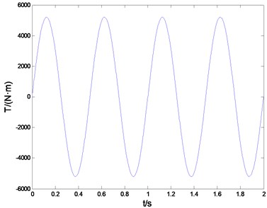
a) Exerted torsion in time domain
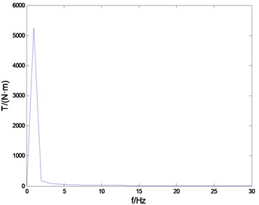
b) Exerted torsion in frequency domain
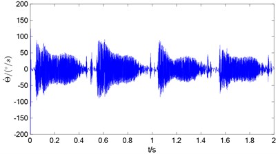
c) Velocity of new brake in time domain
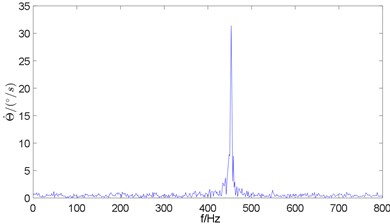
d) Velocity of new brake in frequency domain
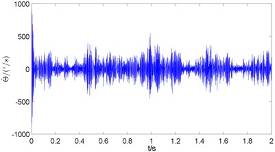
e) Velocity of old brake in time domain
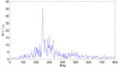
f) Velocity of old brake in frequency domain
4. Limit cycle chatter of foldable cam lever brake
After investigating the difference between the new and old drum brakes under forced vibration, the new brake was validated to have less impact on the drum and less amplitude of vibration.
How is the performance of the other nonlinear vibration? Will shudder, groan or squeal occur under the same conditions?
A test is conducted to answer these questions. The brake is assumed to be fixed on the test bed, and experiments with two different types of initial excited vibration are simulated. The first test establishes that the initial rotational velocity of the leading shoe is 0, and that the shoes are closed in the initial position. The torsion exerted on the cam is constant. No exterior torque is exerted on the drum, but motion is exerted on it, thereby causing the rotational velocity of the brake drum to remain constant at 800 °/s, which is equivalent to a vehicle speed of 10.05 km/h. The initial rotation velocity of the leading shoe is 0. The simulation time is 2 s, and simulation results are shown in Figs. 6(a) to 6(e).
The vibration of the leading shoe has multiple frequencies and amplitudes based on the time domain diagram of the rotational velocity and the rotational displacement of the leading shoe Figs. 6(a)-(c) and the corresponding frequency domain diagram Figs. 6(b)-(d). The main frequency is approximately 300 Hz. For the rotational velocity, a second peak clearly occurs at approximately 600 Hz. This peak is not very clear for the rotational displacement, although a slight peak also occurs at 600 Hz. To determine whether this type of vibration is self-excited, the phase diagram of the rotational displacement and rotational velocity is shown in Fig. 6(e). As shown in the figure, the phase point moves from one point inside one cycle and then near one irregular isolated closed orbit. This closed orbit may be a limit cycle, and thus, an experiment under different initial conditions should be conducted.
Fig. 6Rotational velocity and displacement of leading shoe in time and frequency domains and phase diagram
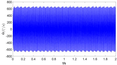
a) Rotational velocity in time domain
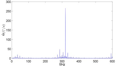
b) Rotational velocity in frequency domain
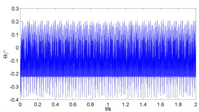
c) Rotational displacement in time domain
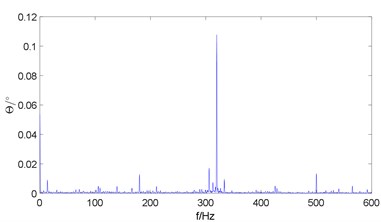
d) Rotational displacement in frequency domain
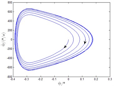
e) Phase diagram
In the second test, the initial rotational velocity of the leading shoe is 800 °/s, and the shoes are closed in the initial position. The torque exerted on the cam is constant. The rotating velocity of the brake drum is also constant at 800 °/s, and the initial rotational velocity of the leading shoe is 800 °/s. The simulation time is 2 s, and simulation results are shown in Figs. 7(a) to 7(e).
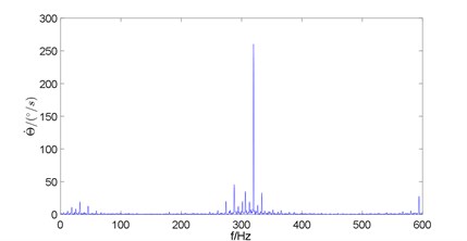
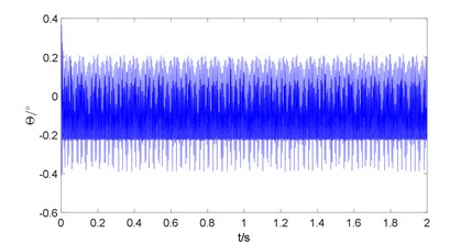
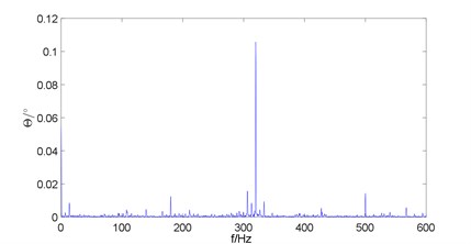
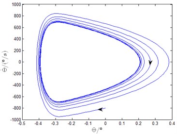
The vibration of the leading shoe has multiple frequencies and amplitudes based on the time domain diagram of the rotational velocity and rotational displacement of the leading shoe Figs. 7(a) to 7(c) and corresponding frequency domain diagram Figs. 7(b) to 7(d). The main frequency is also approximately 300 Hz. Moreover, for the rotational velocity, a second peak clearly occurs at approximately 600 Hz. To determine whether this type of vibration is self-excited, the phase diagram of the rotational displacement and rotational velocity is also shown in Fig. 7(e). As shown in the figure, the phase point moves from one point outside one cycle and then near one irregular isolated closed orbit.
Fig. 7Rotational velocity and displacement of leading shoe in time and frequency domains and phase diagram
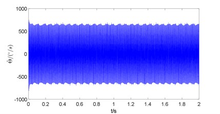
a) Rotational velocity in time domain
b) Rotational velocity in frequency domain
c) Rotational displacement in time domain
d) Rotational displacement in frequency domain
e) Phase diagram
The comparison between Figs. 6 and 7 shows that, when the initial rotational velocities of the leading shoe are different, the shapes of the final closed orbits are the same. As shown in the frequency domain diagram, the values of the frequencies and their corresponding amplitudes with different initial rotational velocities of the leading shoe are the same. The closed orbit is the limit cycle. Nonlinear vibration occurs in the new drum brake under this condition. The parameters of the system should be matched carefully to avoid vibration and noise.
5. Chatter of foldable cam lever brake with multi-layer friction lining
5.1. Introduction of multi-layer friction lining
Numerous methods have been proposed to improve the vibration performance of the brake. In one of these methods, a piece of friction lining with one type of material is divided into several layers with different types of materials. The stiffness and dampness of each friction lining are altered, and the inherent property of the brake system differs, and thus, vibration and noise can be reduced, and the system stability can be improved. As mentioned in [15], the friction lining can be divided into three layers with three different materials. Three layers are the friction layer, buffer layer and basic layer. The friction layer comes in contact with the brake drum, and brake torsion is generated. The buffer layer can absorb vibration. The basic layer supports the entire friction lining. The materials are selected based on the function of each layer. For the friction layer, the material should have medium friction coefficient, and the coefficient should be relatively stable. The abrasion coefficient should be low, and the hardness should be medium. For the buffer layer, the material should have low hardness and good toughness. The material of the basic layer should be sufficiently strong. Three layers are bound together by a relevant chemical material.
Will this method improve the nonlinear vibration of the new brake? This question will be answered in the next test.
In the present study, the friction lining is divided into two layers, and the vibration performance of the new brake is simulated. The inner layer of the new friction lining should be flexible to match the practical friction lining.
5.2. Integration of rigid-flexible coupled model with new friction lining in ADAMS
Firstly, the rigid friction block model created in the INVENTOR is imported into the ADAMS, and the kinetic pairs of constraints between each part are exerted. The inner layer of the friction lining is fixed with the outer layer, and the brake shoes are fixed with the corresponding inner layers. Secondly, the generating function of a flexible body by geometry in the ADAMS is used. The rigid body of the inner layer is generated in the flexible body. Then, the material property of the inner layer is set. Young’s modulus is 3000 N/mm3, Poisson’s ratio is 0.3 and density is 2.7×10⁻⁶ kg/mm3. The inner layer is then meshed. To save running time, element size is set to auto pattern, and the solving modal value is 12. In the option ‘Attachment’, the related ‘Marker’ point is selected as the main node in the function of finding related ‘Markers’. All the nodes in the inner surface of the inner layer are selected as deputy nodes. After meshing the inner layer, the brake shoe is fixed with the flexible inner layer, and the flexible inner layer is fixed with the rigid outer layer [16]. The rigid–flexible coupled model is shown in Fig. 8.
Fig. 8Brake system model with flexible inner friction linings
5.3. Self-excited vibration of new brake with multi-layer friction lining
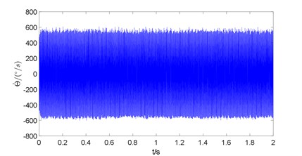
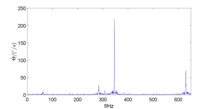
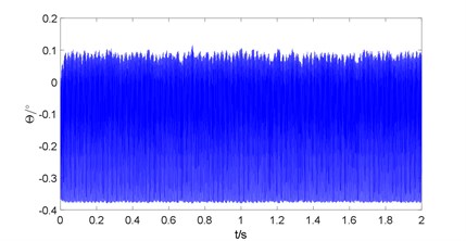
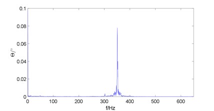
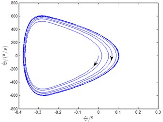
The vibration performance of the new brake with a multi-layer friction lining is tested under two conditions. The first simulation condition is the same as the first test for the original new brake presented in Section 4. The simulation time is 2 s, and the simulation results are shown in Figs. 9(a)-(e).
Fig. 9Rotational velocity and displacement of leading shoe in time and frequency domains and phase diagram of new brake with multi-layer friction lining
a) Rotational velocity in time domain
b) Rotational velocity in frequency domain
c) Rotational displacement in time domain
d) Rotational displacement in frequency domain
e) Phase diagram
The vibration of the leading shoe features multiple frequencies and amplitudes based on the time domain diagram of the rotational velocity and rotational position of the leading shoe Figs. 9(a)-(c) and the corresponding frequency domain diagram Figs. 9(b)-(d). The main frequency is approximately 350 Hz. For the rotational velocity, a second peak occurs at approximately 650 Hz. No such peak occurs for the rotational displacement. To determine whether this type of vibration is self-excited, the phase diagram of the rotational displacement and rotational velocity is shown in Fig. 9(e). As shown in the figure, the phase point moves from one point inside one cycle and then near one irregular isolated closed orbit. This closed orbit may be a limit cycle, and thus, a vibration performance experiment should be conducted under different initial conditions.
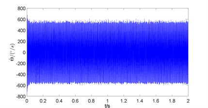
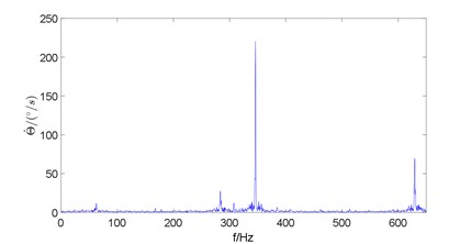
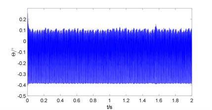
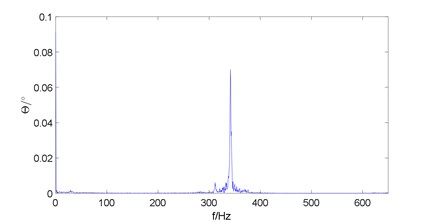
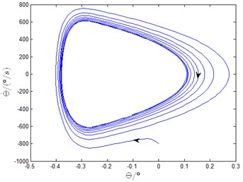
The second simulation condition is the same as the second test for the original new brake presented in Section 4. The simulation time is 2 s, and simulation results are shown in Figs. 10(a)-(e).
The vibration of the leading shoe features multiple frequencies and amplitudes based on the time domain diagram of the rotational velocity and rotational position of the leading shoe Figs. 10(a)-(c) and the corresponding frequency domain diagram Figs. 10(b)-(d). The main frequency is approximately 350 Hz. For the rotational velocity, a second peak clearly occurs at approximately 650 Hz. However, no such peak occurs for the rotational displacement. To determine whether this type of vibration is self-excited, the phase diagram of the rotational displacement and rotational velocity is shown in Fig. 10(e). As shown in the figure, the phase point moves from one point outside one cycle and then near one irregular isolated closed orbit.
Fig. 10Rotational velocity and displacement of leading shoe in time and frequency domains and phase diagram of new brake with multi-layer friction lining
a) Rotational velocity in time domain
b) Rotational velocity in frequency domain
c) Rotational displacement in time domain
d) Rotational displacement in frequency domain
e) Phase diagram
The comparison between Figs. 9 and 10 shows that the initial rotating velocities of the leading shoe are different, and the shapes of the final closed orbits are the same. As shown in the frequency domain diagram, the values of the frequencies and their corresponding amplitudes with different initial rotating velocities of the leading shoe are the same. Thus, the closed orbit is the limit cycle. Moreover, nonlinear vibration still occurs. The multi-layer lining cannot prevent from this type of vibration.
6. Comparison of limit cycle chatter generated by foldable cam lever brake with two types of friction linings
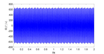
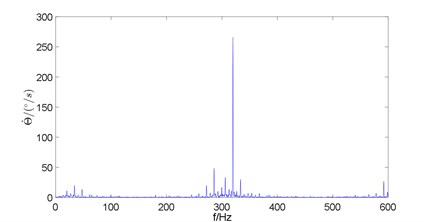
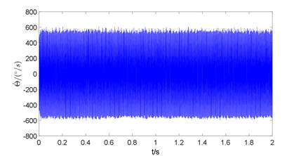
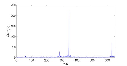
Although the multi-layer friction lining cannot prevent from nonlinear vibration in the new brake system, the amplitude and frequency of vibration can be modified. When the initial rotational velocity of the leading shoe is 0, and the shoes are closed in the initial position, the time domain diagrams and corresponding frequency domain diagrams of the rotational velocity of the leading shoe are shown in Figs. 11(a)-(d).
Fig. 11Rotational velocity of leading shoe in time and frequency domains of new brake with one-layer friction lining and new brake with multi-layer friction lining
a) New brake with one-layer friction lining time domain
b) New brake with one-layer friction lining frequency domain
c) New brake with multi-layer friction lining time domain
d) New brake with multi-layer friction lining frequency domain
Fig. 12Rotational velocity of the leading shoe in time and frequency domains of new brake with one-layer friction lining and new break with multi-layer friction lining
a) New brake with one-layer friction lining time domain
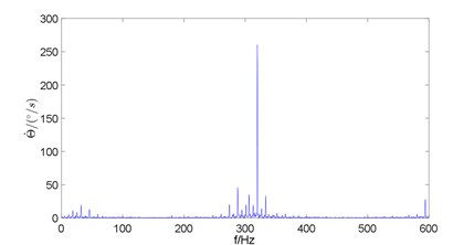
b) New brake with one-layer friction lining frequency domain
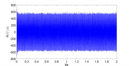
c) New brake with multi-layer friction lining time domain
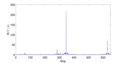
d) New brake with multi-layer friction lining frequency domain
The comparison between Figs. 11(a) and 11(c) shows that when the vibration of the brake shoe is stable, the amplitude of the vibration of the foldable cam lever brake with a multi-layer friction lining is lower than that of the brake with a one-layer friction lining. Moreover, the comparison between Figs. 11(b) and 11(d) shows that the vibration frequency of the foldable cam lever brake with a multi-layer friction lining is lower than that of the brake with a one-layer friction lining. The highest vibration amplitude is also smaller. Hence, the multi-layer friction lining attenuates the amplitude of the vibration of the foldable cam lever brake.
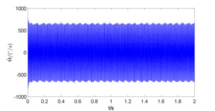
The time domain diagrams and corresponding frequency domain diagrams of the rotational velocity of the leading shoe are shown in Figs. 12(a)-(d) when the initial rotational velocity of the leading shoe is 800 °/s and the shoes are closed in the initial position.
The comparison between Figs. 12(a) and 12(c) indicates that when the vibration of the brake shoe is stable, the amplitude of the vibration of the foldable cam lever brake with a multi-layer friction lining is lower than that of the brake with a one-layer friction lining. Moreover, the comparison between Figs. 12(b) and 12(d) shows that the vibration frequency of the foldable cam lever brake with a multi-layer friction lining is lower than that of the brake with a one-layer friction lining. The highest vibration amplitude is also smaller. Hence, the multi-layer friction lining attenuates the amplitude of the vibration of the foldable cam lever brake.
7. Conclusions
1) In this study, the forced vibration of a new brake based on a foldable cam lever drum brake and that of the old drum brake are compared in the ADAMS. The forced vibration of the former one is better than that of the latter one.
2) The limit cycle chatters of the new brake with a one-layer friction lining and the new brake with a multi-layer friction lining reappear in the ADAMS virtual prototype model. The vibration amplitude and frequency component of the new brake are reduced, thereby making it conducive to provide a stable braking torque output.
3) The establishment of the ADAMS rigid coupling virtual prototype model reproduces a friction plate after the stratification of the limit cycle oscillation of the drum brakes based on the new brake friction plate, which is divided twice into rigid coupling. The self-excited vibrations of the new brake with a one-layer friction lining and that of the brake with a multi-layer friction lining are compared. The comparison shows that the multi-layer friction lining can improve the characteristics of the self-excited vibration for the new brake.
4) During the simulation of the automobile drum brake vibration characteristics using the ADAMS model, self-excited vibration does not occur in the drum brake with the cam. This result should be further studied and combined with a bench test in future works.
References
-
Mills H. R. Brake Squeak. Technical Report 9000B, Institution of Automobile Engineers, 1938.
-
Spurr R. T. Theory of brake squeal. Proceedings of the Automobile Division, Institution of Mechanical Engineers, Vol. 1, 1961, p. 33-52.
-
North M. R. Disc brake squeal. Braking of Road Vehicles, Automobile Division of the Institution of Mechanical Engineers, Mechanical Engineering Publications Limited, London, England, 1976, p. 169-176.
-
Bowden F. P., Leben L. Nature of sliding and analysis of friction. Royal Society of London Proceedings Series A Mathematics Physics and Engineering Science, Vol. 169, 1939, p. 371-391.
-
Morgan F., Musjat M., Reed D. W. Friction phenomena and stick-slip process. Journal of Applied Physics, Vol. 12, Issue 10, 1941, p. 743-752.
-
Nosrati Ali, Farshidianfar Anoushiravan Analytical approximations for stick-slip vibration amplitudes based on discretization method. 16th International Congress on Sound and Vibration, Poland, 2009, p. 1-8.
-
Crowther Ashley R., Singh Rajendra Analytical investigation of stick-slip motions in coupled brake-driveline systems. Nonlinear Dynamic, Vol. 50, 2007, p. 463-481.
-
Zhang Jin, Zhang Nong, Crowther Ashley R. Analytical study of brake groan through coupled 2-dof brake model. Jaoan Journal of Industrial and Applied Mathematics, Vol. 25, 2011, p. 205-222.
-
Jan Awerjcewicz, Pawel Olejinik Friction pair modeling by 2-dof system: numerical and experimental investigation. International Journal of Bifurcation and Chaos, Vol. 15, Issue 6, 2005, p. 1931-1944.
-
Wei Daogao, Li Lili, Shi Wei, Li Tianpei, Zhang Jiyu Multiple limit cycles of a dual-cylinder dual-pad brake system caused by dry friction. Journal of Vibroengineering, Vol. 17, Issue 7, 2015, p. 3949-3966.
-
Khalid Abdelhamid Mohamed Creep groan of disc brakes. SAE Paper 951282, 1995.
-
Zhou Minggang Study on Theory and Characteristic of Low Frequency Vibration for Drum Brake. Huazhong University of Science and Technology, Wuhan Hubei, 2006.
-
Xu John Disc brake low frequency creep groan simulation using ADAMS. International ADAMS User Conference, Orlando, Florida, USA, 2000.
-
Zhang Wanzhou An Expanding Mechanism with Folding Mandrill Used on the Internal-Expanding Drum Brake. Utility Model. Patent No. ZL201120521335X.2011.12, China.
-
Lin Ronghui, Sun Xixiang, Lin Tianxiang, Zhang Jinghui Development of brake linings with three-layer structure for bus drum brakes. Non-Metallic Mines, Vol. 37, Issue 5, 2014, p. 81-83.
-
Cui Hongbin, Wang Jiaxu, Zhao Hui, Xiao Ke, Yu Bo, Du Haiwei Dynamic analysis of rubber alloy filtering gear reducer based on ADAMS. Mechanical Science and Technology for Aerospace Engineering, Vol. 33, Issue 5, 2014, p. 652-656.
About this article
This project is supported by the National Natural Science Foundation of China (Grant Nos. 51375130 and 51050002). Open Foundation of State Key Laboratory of Automotive Safety and Energy of Tsinghua University (KF2007-05) and Geely Automobile Research Institute Open Fund (2009E10013).
