Abstract
Rear axle compliance steering (RACS) is a technology of passive four-wheel steering, which is designed to improve the vehicle handling and stability at medium or high speed. This paper focuses on the dynamic behavior of the vehicle with RACS. Firstly, the compliance steering principle for different rear suspensions is illustrated. Then, the viscoelastic members with fractional order derivative properties are introduced into RACS, and the fractional order model of RACS is formulated. Next, the dynamic model of the vehicle with RACS is established, the adjusting rules for the compliance steering stiffness are derived, and the vehicle stability is investigated. Finally, numerical experiments are performed to illustrate the effects on the vehicle dynamic behavior caused by the compliance steering stiffness, the viscoelastic members and the vehicle longitudinal velocity. Research results show that, the vehicle with RACS has better dynamic characteristics than that without RACS at medium or high speed; and the compliance steering stiffness, the viscoelastic members and the vehicle longitudinal velocity have different impacts on the vehicle lateral dynamic behavior.
1. Introduction
As one of effective rear wheel steering modes for passenger cars, rear axle compliance steering (RACS) is popularly adopted to improve the vehicle stability at high speed [1, 2]. RACS utilizes the tire lateral force and the lateral elasticity of the rear suspension rather than any special steering mechanism. This can make the rear axle turn in the same direction as that of the front wheels at medium or high speed, reduce the vehicle sideslip angle at the center of gravity (CG), and thus improve the vehicle lateral stability. These features make RACS applied broadly and widely in various kinds of cars.
From the academic perspective, the research problem for RACS is how to rationally use the compliance characteristics of the rear suspension. Previous studies on this problem can be classified as two streams in terms of the research method: one is experimental method, and the other is numerical method. In the former stream, Momiyama and Miyazaki [2] investigated the compliance under steer technology of the rigid axle rear suspension through calculation and the actual vehicle test; Mou [3] studied the steering characteristics of the compliance suspension used in Citroën-ZX series cars through experiments; Pan et al. [4] analyzed the rear axle compliance steering performance of the vehicle with five-link non-independent rear suspension and verified the results through experiments. In the latter stream, Guo and Yin [1] illustrated the rear axle compliance structure for torsion beam suspension and revealed its compliance steering principle; Li and Chen [5] performed stability and robustness of compliance steering system; Ticã et al. [6] studied the influence of compliance on an elastokinematic model of a proposed rear suspension; Wang et al. [7] carried out a preliminary research on the relationship between compliance steering stiffness and vehicle yaw rate. Compared with experimental method, numerical method is advantageous to simulate and explore the parameter relationships as well as sensitivity analyses from dynamic and evolution perspective.
Generally, the research on RACS is still in development in the academic community. Several previous studies investigated the rear suspension design problem to improve vehicle handling and stability [8, 9], but, to the best of our knowledge, very rare literature investigated the relationships among compliance steering stiffness and dynamic behavior and vehicle working conditions.
The motivation of this study is to investigate the relationships among compliance steering stiffness and vehicle dynamic behavior and vehicle working conditions, by using numerical method. The contributions contain three aspects: (1) incorporate viscoelastic members with fractional order derivative properties into RACS, and then formulate it as a fractional order model; (2) reveal the adjusting rule of the compliance steering stiffness varying with the vehicle longitudinal velocity; (3) perform the influence of the viscoelastic member’s characteristic parameters on the vehicle dynamic behavior.
The structure of this paper is organized as follows. In Section 2, the operating principle of RACS is illustrated. In Section 3, the dynamic model of the vehicle with RACS is formulated and discussed. In Section 4, the numerical experiments are performed and analyzed. Finally, the concluding remarks are provided in Section 5.
2. Operating principle of RACS
This section mainly illustrates the operating principle of RACS for different rear suspensions. Even though RACS has different implementation ways due to different types of suspensions, it has the same technical principle. Through ingenious design of the connection structure between the rear axle and the vehicle body, RACS makes the rotation center of the rear axle pertain to the vehicle body move backward, and then by means of the lateral tire force compels the rear axle to rotate through an angle.
The technology of RACS was firstly used in those cars with torsion beam rear suspensions, such as Citroën Fukang, Citroën Elysée, Volkswagen Golf IV, the Audi A3 and Bora. Fig. 1 shows the arrangement of the rubber bushings on the rear axle frame of the torsion beam suspension [1]. Suppose that the vehicle turns left, the lateral force suffered by the rear wheels points to the left. Because the two front bushings are elastic in - direction and rigid in B-B direction, they can only move in - direction and their instantaneous velocities intersect at the point . The distance from point to the acting point of is denoted by . With the action of the whole rear axle frame rotates counterclockwise around the point , namely the rear axle turns in the same direction as that of the front wheels, which intensifies the trend of understeer and reduces the equivalent sideslip angles of the rear axle.
Fig. 1Top view of RACS schematic diagram for torsion beam suspension [1]
![Top view of RACS schematic diagram for torsion beam suspension [1]](https://static-01.extrica.com/articles/17580/17580-img1.jpg)
For the double wishbone suspension, the compliance steering of rear wheels is actualized by using different stiffness rubber bushings which connect the -shaped control arm to the vehicle body [10].
Fig. 2 shows the compliance steering principle of the rear axle for five-link suspension [4]. The lower drag links and are parallel to the vehicle longitudinal axis. The intersect point of the upper drag links and is the yaw rotation center of the rear axle. The transversal push rod lies behind the rear axle, and the two ends of rod are connected to the vehicle body through rubber bushings. The radial stiffness of rubber bushings used in rod is almost five times as those bushings used in drag links and . When the vehicle turns a corner, the lateral force of the rear axle is mainly undertaken by the rubber bushings used in rod . And then the whole rear axle turns in the same direction as the front wheels. Obviously, the positions of rods , and are crucial for determining the steering characteristics of the vehicle.
Fig. 2Top view of RACS schematic diagram for five-link suspension [4]
![Top view of RACS schematic diagram for five-link suspension [4]](https://static-01.extrica.com/articles/17580/17580-img2.jpg)
3. Theoretical formulation
In this section, the fractional order model of RACS is formulated, and the dynamic model of the vehicle with RACS is established and discussed.
3.1. Fractional order model of RACS
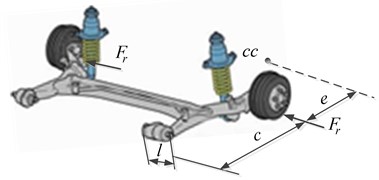
From Section 2 it can be seen that, elastic bushings are key components for actualizing rear axle compliance steering. In the present study, in order to investigate the feasibility of adjusting the compliance steering angle through changing the viscoelastic material parameters, the viscoelastic members replacing elastic bushings are introduced into RACS. Fig. 3 shows the schematic diagram of RACS with viscoelastic members. As shown in Fig. 3, is the axial length of the viscoelastic member; is the distance from the axis of the viscoelastic member to the rear axle; is the yaw rotation center of the rear axle and is the distance from the point to the acting point of lateral force .
Fig. 3Schematic diagram of RACS with viscoelastic members
A generalized standard linear solid model with two independent fractional parameters is adopted to describe the behavior of the viscoelastic member [11], as given in Eq. (1):
where is the stress, is the strain, is the relaxation time, is the retardation (creep) time, is the relaxed magnitude of the elastic modulus, and , and are parameters dependent on the material. Parameters and , are fraction, and respectively represent Riemann-Liouville fractional derivatives with the order and , which are defined in Eq. (2) [12]:
In which, is the fractional order of the time derivative, represents the operator of fractional derivation of th order, denotes the Euler gamma function [13].
Assume that the viscoelastic member is homogeneous and let the two sides of Eq. (1) multiply by the cross section area of the viscoelastic member, then the Eq. (3) can be obtained:
In which, is the axial force of the viscoelastic member caused by the compliance steering.
According to Fig. 3, the strain of the viscoelastic member can be written as:
where is the compliance steering angle of the rear axle.
Ignoring the rotational inertia of the RACS, and considering the equilibrium relation between the rear wheel lateral force and the axial force of the viscoelastic member , the Eq. (3) can be derived as:
where is the compliance steering stiffness. Implementing Laplace transform of Eq. (5), the compliance steering angle of the rear axle can be derived as:
3.2. Dynamic model of the vehicle with RACS
Fig. 4 shows a two-degree-of-freedom model including yaw and lateral motion dynamics of the vehicle with RACS.
Fig. 4Dynamic model of the vehicle with RACS
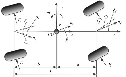
In this model the coordinate system is fixed on the vehicle center of gravity which is denoted as . and denote the vehicle longitudinal and lateral directions, respectively; , represent the front and rear tire lateral forces, respectively; , represent the velocities of the front and rear axles, respectively; , represent the sideslip angles of the front and rear tires, respectively; is the steering angle of the front wheel and is the compliance steering angle of the rear axle; is the angle between the axis and the velocity direction of , which is usually called equivalent sideslip angle and its numerical value equals to ; and denote the longitudinal and lateral velocities of the vehicle , respectively, and is supposed to be constant in the present study; is the vehicle sideslip angle at and ; is the yaw rate of the vehicle.
Assume that the sideslip angle is small and , then the sideslip angels of front and rear tires can be written as:
where and are the distance from to the front and rear axles respectively, and is the wheelbase.
The tire lateral force of the front and rear wheels are considered as linear functions of their sideslip angles, which can be written as:
where and represent the cornering stiffness of the front and rear tires, respectively.
According to Fig. 4 and considering the previous force, the vehicle model including lateral and yaw motions can be expressed as:
where is the vehicle mass, denotes the vehicle moment of inertia about the yaw axis.
3.3. Adjusting rules for compliance steering stiffness
Implementing Laplace transform of Eq. (9), two transfer functions and from the front wheel step steering input to the sideslip angle and the yaw rate are yielded as Eq. (10) and Eq. (11):
where:
Sideslip angle of the vehicle is an important parameter for evaluating the vehicle lateral stability. Zero sideslip angle ( 0) is always the control object for the vehicle with active or semi-active steering system. 0 is helpful to improve the vehicle lateral stability. According to Eq. (10), Eq. (12) can be obtained and which indicates that the steady-state value of sideslip angle for the vehicle with RACS is influenced by the vehicle mass, the position of , the cornering stiffness of front and rear tires, the vehicle longitudinal velocity and the compliance steering stiffness of RACS. Therefore, when vehicle working conditions change, the steady-state value of the sideslip angle can be kept unchanged through adjusting the compliance steering stiffness :
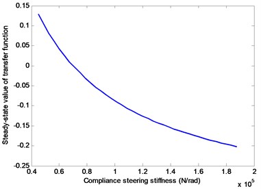
According to Eq. (12) and Table 1, when 20 m/s Fig. 5 can be obtained, which depicts the relationship between the steady-state value of and compliance steering stiffness In Fig. 5, the steady-state value of changes nonlinearly with When equals to some value, the steady-state value of equals to zero. That means changing can make the steady-state value of the sideslip angle equal to zero, which is helpful to improve the lateral stability of the vehicle with RACS.
Fig. 5Relationship between steady-state value of Gβ(s) and Cs
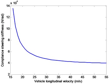
Let the numerator of Eq. (12) equal to zero, the relationship between the longitudinal velocity and the compliance steering stiffness can be obtained as:
Fig. 6 shows the adjusting rule of the compliance steering stiffness changing with the vehicle longitudinal velocity , where decreases nonlinearly with increasing. Especially, when lies in [18, 40] m/s (i.e., [64.8, 144] km/h), has better adjusting effect; when is larger than 40 m/s, has very little changes; when is lower than 18 m/s, approaches to infinite. Therefore, at the case of lower speed, RACS should stop working, and the vehicle should switch into the common working mode which turns a corner with two front wheels.
Fig. 6Adjusting rule for the compliance steering stiffness Cs
3.4. Investigation of the vehicle stability
In order to assess the ability of the vehicle dynamic system withstanding the disturbance, the stability of the vehicle dynamic system is investigated in this subsection.
According to Eq. (5)-Eq. (9), the state space model of the vehicle motion can be expressed as:
where is the matrix of the state variables consisting of the yaw rate and the sideslip angle . can be expressed as:
The coefficient matrices in Eq. (14) are listed as follows:
In which, and .
According to Lyapunov’s method [14], the Lyapunove function for verifying the stability of Eq. (14) can be given as:
where is a 2×2 matrix, is the unit matrix. If the eigenvalue of are all positive, the system defined in Eq. (14) is stable; otherwise, the system is unstable.
The key parameters of the vehicle and tires used in this study are listed in Table 1.
Table 1Vehicle and tire parameters [15]
Parameters | Values | Unit | Parameters | Values | Unit |
1740 | kg | –35000 | N/rad | ||
1.035 | m | –37500 | N/rad | ||
1.655 | m | 3048 | kg·m2 |
Based on the above Lyapunove stability criteria, some numerical experiments under different working conditions and sensitive parameters given in Table 2 are carried out to verify the system stability against the perturbation and disturbance. Research results show that the vehicle dynamic systems are all stable under different numerical experiments. In other words, the vehicle with RACS has strong ability to resist the perturbation and disturbance.
Table 2Working conditions and sensitive parameters
Working conditions | Sensitive parameters | |||||||
30 (m/s) 0.3 0.7 | (m) | |||||||
0.935 | 1.035 | 1.135 | 1.235 | 1.335 | 1.435 | 1.535 | 1.635 | |
1.035 (m) 0.3 0.7 | (m/s) | |||||||
5 | 10 | 15 | 20 | 25 | 30 | 35 | 40 | |
1.035 (m) 30 (m/s) 0.5 | ||||||||
0.1 | 0.2 | 0.3 | 0.4 | 0.5 | 0.6 | 0.7 | 0.8 | |
1.035 (m) 30 (m/s) 0.5 | ||||||||
0.1 | 0.2 | 0.3 | 0.4 | 0.5 | 0.6 | 0.7 | 0.8 | |
4. Numerical experiments
In this section, numerical experiments are carried out to investigate the dynamic behavior of the vehicle with RACS, and the effects on the vehicle dynamic behavior caused by the compliance steering stiffness , the viscoelastic members used in RACS and the vehicle longitudinal velocity . All performed numerical experiments are conducted with the same step steering input . The output variables of the vehicle dynamic system are yaw rate , sideslip angle and compliance steering angle .
4.1. Effects of compliance steering stiffness
In this part, the effects of compliance steering stiffness on the dynamic behavior of the vehicle with RACS are investigated. For all numerical cases in this part, the related parameters of the vehicle are set as 20 m/s, 0.3, 0.7 and the values of and are referred to Eldred et al. [16]. And is used to measure the compliance steering stiffness and the values of are set as –1.5, –3, –4.5, respectively. Note that, the compliance steering stiffness remarkably grows with the increasing of absolute value.
Fig. 7 shows the effects of on the sideslip angle of the vehicle . The steady-state value of sideslip angle for the vehicle with RACS is obviously smaller than the vehicle without RACS, which means the vehicle with RACS has better vehicle body posture when it turns a corner. Moreover, the steady-state value of is more and more close to zero with the decreasing of In other words, reducing the compliance steering stiffness can dramatically make the sideslip angle decreased to zero.
Fig. 8 shows the effects of on the yaw rate of the vehicles. It can be seen that the steady-state value of yaw rate for the vehicle with RACS is obviously smaller than the vehicle without RACS. The steady-state value of yaw rate is obviously decreasing with the reduction of the compliance steering stiffness. It should be noted that the smaller yaw rate means the driver needs to turn more steering wheel angle for the same turning radius.
Actually, the vehicle without RACS is a special case of the proposed model of vehicles with RACS. As the curves demonstrated in Fig. 7 and Fig. 8, when changes from –1.5 to –4.5, the curves of vehicle with RACS are approaching to those of vehicle without RACS. At the extreme case, let compliance steering stiffness equal to a large enough value, the curves would have overlapped each other between vehicles with RACS and without RACS. Furthermore, in Fig. 7 and Fig.8, the curves of vehicle without RACS are consistent with the results given in [17, 18]. Therefore, it could be concluded that, the proposed model of vehicle with RACS in this study is more generalized and includes the dynamic behavior of the vehicle without RACS.
Fig. 9 shows the effects of on the compliance steering angle . The compliance steering angle increases with decreasing, namely reducing the compliance steering stiffness can increase the compliance steering angle. Furthermore, the compliance steering angles are all small and within the deformation range for the viscoelastic members used in RACS. Therefore, it is completely feasible to change the compliance steering angle through adjusting the compliance steering stiffness.
Fig. 7Effects of Cs/kr on the sideslip angle
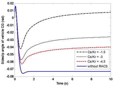
Fig. 8Effects of Cs/kr on the yaw rate
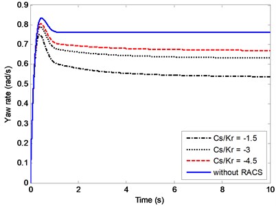
Fig. 9Effects of Cs/kr on the compliance steering angle
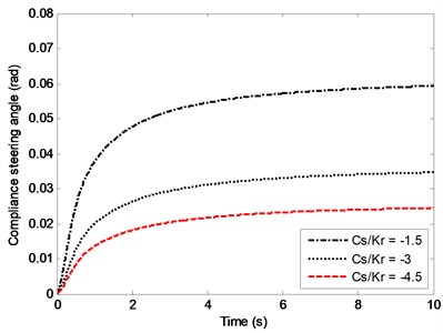
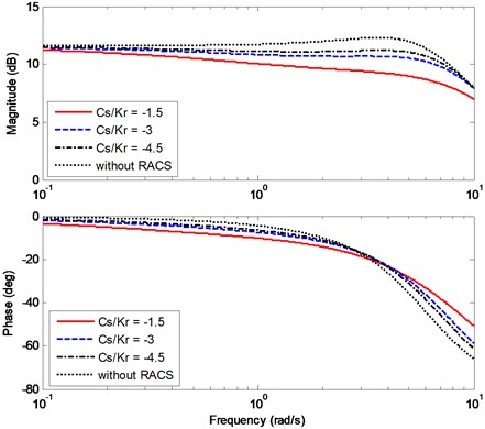
Fig. 10 and Fig. 11 depict the effects of on the bode diagrams of sideslip angle and yaw rate transfer functions. Bode diagram includes magnitude-frequency characteristic and phase-frequency characteristic. In the present study, magnitude-frequency characteristic reflects the ability of the vehicle to accurately perform the steering instructions at different frequencies. Phase-frequency characteristic reflects the phase difference between the vehicle dynamic response and the front wheel steering angle input varying with the frequency. Considering the vehicle steering process at medium speed or high speed belongs to a low frequency motion and the working frequency for the driver turns the steering wheel is always within 1 rad/s [17], this study focuses on the steering frequency between 0.1 rad/s and 10 rad/s.
In Fig. 10, the magnitude-frequency characteristic shows the varying of sideslip angle gain with the steering frequency, where the magnitude-frequency curve of the vehicle without RACS is obviously higher than those of the vehicle with RACS. With the increasing of steering frequency, the phase difference between the sideslip angle and the steering angle input is decreasing. Besides, the phase difference of the vehicle without RACS is generally a little larger than those of the vehicle with RACS.
In Fig. 11, the magnitude-frequency characteristic shows the curves almost have the same steady-state gain of the yaw rate. For the curve of the vehicle without RACS, there is a peak point, which means at that frequency a little distortion appears for the vehicle performing the driver’s steering instructions. For the curves of and –45, they both have good performance in carrying out the steering motion; for the curve of –1.5, the magnitude of the yaw rate is decreasing with the steering frequency increasing. Summarily, the compliance steering stiffness has little impact on the phase-frequency characteristic.
Fig. 10Effects of Cs/kr on the bode diagram of Gβ(s)
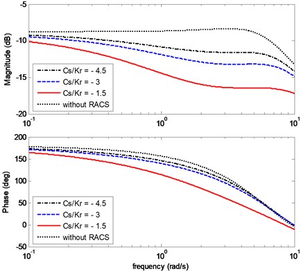
Fig. 11Effects of Cs/kr on the bode diagram of Gωr(s)
4.2. Effects of viscoelastic member
This subsection investigates effects of the viscoelastic member used in RACS on vehicle dynamic behavior. In the numerical cases, the vehicle longitudinal velocity 20 m/s, the fractional orders and are set as 0.2, 0.4, and 0.6, 0.8, respectively. The parameters and are related to the material properties of the viscoelastic member. The relationship between and is in accordance with Eq. (13).
Fig. 12 and Fig. 13 show the effects of fractional orders and on the sideslip angle and yaw rate of the vehicle with RACS. It can be observed that has little effect on the sideslip angle and nearly no effect on the yaw rate. The fractional order has obvious effect on the sideslip angle and a little effect on the yaw rate. Furthermore, the larger the order is, the closer to zero the sideslip angle is, and the smaller the yaw rate is. Fig. 14 depicts the effects of fractional orders and on the compliance steering angle. It is easy to see that the order has little effect and the order has obvious effect on the compliance steering angle. The larger the order is, the larger the compliance steering angle is.
Fig. 12Effects of α and γ on the sideslip angle
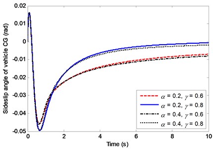
Fig. 13Effects of α and γ on the yaw rate
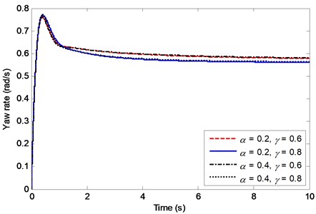
Fig. 14Effects of α and γ on the compliance steering angle
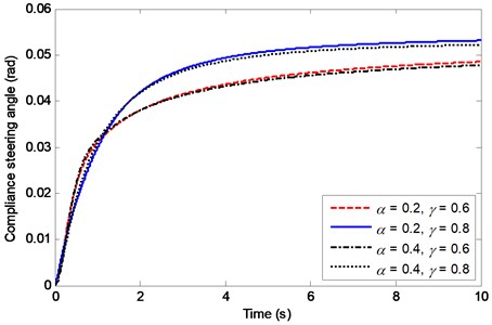
Obviously, the two fractional parameters and of the viscoelastic member have distinct effects on the vehicle dynamic behavior, which provides an important guidance for the choice of viscoelastic member used in RACS. With the increasing of the sideslip angle is more and more close to zero, which is more and more beneficial for improving the vehicle lateral stability. The effects of increasing order on the vehicle dynamic behavior are similar to those of reducing compliance steering stiffness.
4.3. Effects of vehicle longitudinal velocity
In this subsection, the effects of vehicle longitudinal velocity on the dynamic behavior of the vehicle with RACS are investigated. For all numerical cases in this part, the fractional orders are set as 0.3 and 0.7, are set as 20 m/s, 30 m/s, 40 m/s and 50 m/s, respectively. The relationship between and is in accordance with Eq. (13).
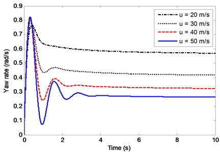
Fig. 15 and Fig. 16 show the effects of on the sideslip angle and the yaw rate. From the two figures, it can be seen that the curves present obvious fluctuation phenomenon before reaching the steady-state values when is larger than 40 m/s. This phenomenon is related to the structure parameters of the vehicle. Fig. 15 indicates that for different vehicle velocity, if the compliance steering stiffness is adjusted according to Eq. (13), the sideslip angle of vehicle can always tend to be zero. Fig. 16 shows that steady-state yaw rate decreases obviously with the increasing of , which means at higher speed the driver needs to steer more steering wheel angle for the same turning radius.
Fig. 15Effects of u on the sideslip angle
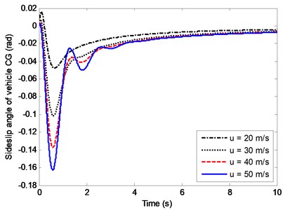
Fig. 16Effects of u on the yaw rate
Effects of on the compliance steering angle are shown in Fig. 17. Before reaching the steady-state value, the curves also experience slight fluctuation at high speed, and the larger the velocity is, the more obvious the fluctuation is. The smaller compliance steering stiffness will make the compliance steering angle appear unstable before reaching its steady-state value.
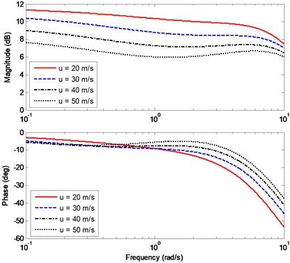
In Fig. 18 and Fig. 19, the curves demonstrate how impacts the bode diagrams of and . For the cases of equals to 20 m/s, 30 m/s, 40 m/s, 50 m/s, the adjusting rules of are obtained by Eq. (13). In Fig. 18, the magnitude-frequency curves show the vehicle with RACS has different steady-state gains of sideslip angles at different . Along with the decreasing of , the magnitude of is also decreasing within the working frequency, which means the sideslip angle is gradually close to zero. The phase-frequency curves show that within the working frequency the phase difference between the input and the output has little variation for different . In Fig. 19, the magnitude of yaw rate is inversely proportional to , which is compatible with the time domain results in Fig. 16. The magnitude-frequency curves are slightly decreasing with the increasing frequency. In other words, at the same , the vehicle with RACS has good steering performance within the working frequency. Moreover, the phase-frequency curves have little difference at different within the working frequency. When the steering frequency equals to 0.1 rad/s the phase delay is small, which means the vehicle has good steering response performance when the driver turns the steering wheel at low speed.
Fig. 17Effects of u on the compliance steering angle
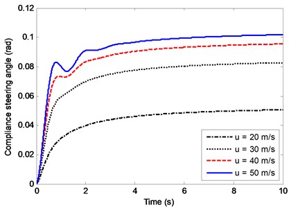
Fig. 18Effects of u on the bode diagram of Gβ(s)
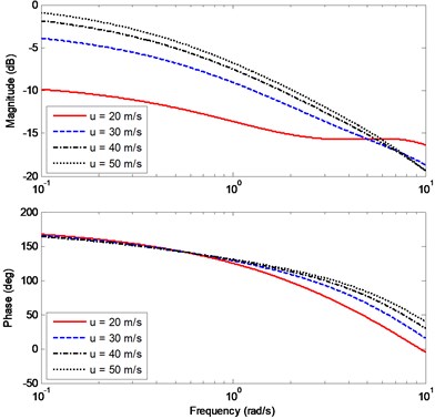
Fig. 19Effects of u on the bode diagram of Gωr(s)
5. Conclusions
In this paper, the dynamic behavior of the vehicle with RACS has been investigated. Firstly, the operating principle of RACS has been illustrated. Secondly, the fractional order model of RACS with viscoelastic members has been formulated, and the dynamic model of the vehicle with RACS has been proposed. Thirdly, the relationship between the steady-state value of sideslip angle transfer function and the compliance steering stiffness , the adjusting rule of has been analyzed, and the vehicle stability has been investigated. Fourthly, the impacts on the vehicle dynamic behavior have been investigated from the three aspects, i.e., the compliance steering stiffness, the viscoelastic members and the vehicle longitudinal velocity. Finally, many numerical experiments have been conducted in terms of time domain and frequency domain, respectively.
Some findings can be summarized as follows: (1) if the vehicle runs at lower speed, RACS should stop working and the vehicle should switch into the common working mode which turns with two front wheels; (2) the compliance steering angle is inversely proportional to the compliance steering stiffness, and the sideslip angle and the yaw rate are proportional to the compliance steering stiffness; (3) the vehicle with RACS has strong ability to resist the perturbation and disturbance. (4) compared with the vehicle without RACS, the vehicle with RACS has lower sideslip angle, yaw rate and a little larger response time; (5) for the dynamic behavior of the vehicle with RACS, the viscoelastic parameter has obvious impact, while the parameter has tiny impact.
The most direct natural extension involves carrying out physical experiments to verify the analytical results and numerical simulation in this study. Other promising directions of future research are the investigation on control strategies and control algorithms of the compliance steering stiffness.
References
-
Guo K. H., Yin C. L. The steering principle and handling stability analysis of compliance suspension. Automotive Engineering, Vol. 19, Issue 6, 1997, p. 321-324, (in Chinese).
-
Momiyama F., Miyazaki K. Compliance steer and road holding of rigid rear axle for enhancing the running straightness of large sized vehicles. International Truck and Bus Meeting and Exposition, 1993.
-
Mou X. D. The Preliminary Study of Side Leans Steering the Characteristic to Passenger Vehicle Compliance Suspension. SAE Technical Paper, 2007-01-3639.
-
Pan X., Lin Y., Chen X. K., Wang D. C. Rear axle compliance steering performance analysis of five-link dependent rear suspension. Journal of Southwest Jiaotong University, Vol. 47, Issue 3, 2012, p. 477-483., (in Chinese).
-
Li B., Chen S. H. A research on the analysis and synthesis method of compliance steering. Automotive Engineering, Vol. 28, Issue 9, 2006, p. 829-833.
-
Ticã M., Dobre G., Mateescu V., Virzi-Mariotti G. Influence of compliance for an elastokinematic model of a proposed rear suspension. International Journal of Automotive Technology, Vol. 15, Issue 6, 2014, p. 885-891.
-
Wang Y., Chen N., Tian J., Xu X. M. Handing performances of vehicle with a fractional compliant rear-wheel steering system. IEEE International Conference on Fractional Differentiation and Its Applications (ICFDA), 2014, p. 1-6.
-
Blundell M. V. The influence of rubber bush compliance on vehicle suspension movement. Materials and Design, Vol. 19, Issues 1-2, 1998, p. 29-37.
-
Gao X., Jiang D., Wang Y. The research of effects of suspension bushing stiffness on vehicle yaw response performance. International Conference on Electric Information and Control Engineering, 2011, p. 6283-6286.
-
Afkar A., Mahmoodi-Kaleibar M., Paykani A. Geometry optimization of double wishbone suspension system via genetic algorithm for handling improvement. Journal of Vibroengineering, Vol. 14, Issue 2, 2012, p. 827-837.
-
Rossikhin Y. A., Shitikova M. V. Analysis of rheological equations involving more than one fractional parameters by the use of the simplest mechanical systems based on these equations. Mechanics of Time-Dependent Materials, Vol. 5, Issue 2, 2001, p. 131-175.
-
Zhou Y. Basic Theory of Fractional Differential Equations. World Scientific, Singapore, 2014.
-
Ross B. A Brief History and Exposition of the Fundamental Theory of Fractional Calculus- Fractional Calculus and its Applications. Springer Berlin Heidelberg, 1975.
-
Khalil, H. K. Nonlinear Systems. Third Edition, Upper Saddle River, Prentice-hall, 2002.
-
Yin G. D., Chen N., Wang J. X., Wu L.Y. A study on μ-synthesis control for four-wheel steering system to enhance vehicle lateral stability. Journal of Dynamic Systems Measurement and Control, Vol. 133, Issue 1, 2011, p. 11002-11006.
-
Eldred L. B., Baker W. P., Palazotto A. N. Kelvin-Voigt versus fractional derivative model as constitutive relations for viscoelastic materials. AIAA Journal, Vol. 33, Issue 3, 2015, p. 547-550.
-
Guiggiani M. The Science of Vehicle Dynamics. Springer, Netherlands, 2014.
-
Bai Y., Ren X., Xu Y. F., Wu F. W. Factors affecting dynamic characteristics of driver steering control. Journal of Chang’an University, Vol. 35, Issue 4, 2015, p. 112-118.
Cited by
About this article
Authors of the paper would like to express appreciation of the supports from National Natural Science Foundation of China (51605228), Jiangsu Natural Science Foundation (BK20160742), Youth Science and Technology Innovation Project of Nanjing Forestry University (CX2016028), Jiangsu Postdoctoral Research Foundation (1402084C).
