Abstract
Vortex Induced Vibration (VIV) is a major challenge in the design of tubular members under second order wave effects. Providing helical strakes have proven to eliminate presence of VIV, but at the cost of increased drag. Two different approaches of VIV suppression are discussed in the present study and compared. Concept of suppressing vibration by tripping the boundary layer of incoming flow using stripping wires is experimentally investigated. It is seen that the position at which boundary separates has an important role in response behavior of the cylinder. Effect of lock-in point at higher reduced velocities is quantified. Alternative study is also carried out by disrupting the correlation of flow in a stepped cylinder where an abrupt change in diameter in imposed by design. For comparison, vibration of stepped cylinder, attached with tripping wire is also examined. Results from the studies showed VIV suppression under both the independent configurations but a significant improvement is seen in the latter case.
1. Introduction
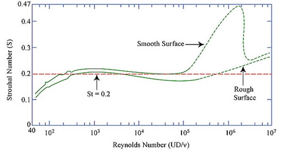
When a flow happens around a solid body, flow downstream of the body separates into a time periodic alternating formation of vortices at certain speeds. Reduction of forces on cylindrical members in offshore structures is on a continuous attempt [1-4]. Rehabilitation of offshore structures are generally governed by desirous damage caused due to large displacements and in-plane stresses [5-7]. Vortex Induced vibrations are the result of such exciting forces generated by vortex shedding on the hull of a bluff body, causing response near the resonant period [8]. Due to VIV, structure undergoes number of stress cycles, leading to fatigue damage [9, 10]. Considering the possibilities of such significant damages, various VIV suppression configurations are encouraged. Free vibration studies carried out in this domain have involved both experimental and computational studies of single and two degree of freedom systems of rigid, flexible, pivoted, cantilevered cylinders [11, 12]. Early studies involved systems that used air as the working fluid and had a non-dimensional mass [13]. Khalak and Williamson (1991) testified large amplitude response, which is recently observed in systems that used water as working fluid [14, 15]. Numbers of methods are developed to suppress VIV but, factors such as cost and difficulty of implementation often restricted their applications with the exception of strakes. Despite a higher cost, helical strakes are recommended to strengthen the cylindrical member against larger bending moments that arise from increased drag [16]. Experimental studies are also supporting the fact of VIV suppression with reduced drag in marine risers, which are effective for flexible cylinders. VIV suppression systems are circumscribed around low mass and damping phenomenon [17]. Present study is focused on a VIV suppression system of a rigid cylinder that resembles hull of a Spar. Behavior of cylinder response over a wide range of velocity is analyzed to determine the effectiveness of suppression by various methods namely: i) tripping boundary layer; ii) abrupt change in diameter of cylinder along span; and iii) their combined effect. Vortex shedding is an effect of viscosity and Reynolds number on the fluid flow around cylinder. It is known that at low Reynolds number, viscous forces dominate the flow while at high Reynolds number, inertial forces dominate. Vortex shedding frequency (), which is also called as Strouhal frequency is related to a non-dimensional Strouhal number, . The Strouhal number of a static pipe or a cylinder is a function of Reynolds number, surface roughness of the body and the turbulence of the free stream. It is seen that Strouhal number is about 0.2 over a large range Reynolds number, as seen in Fig. 1.
Fig. 1Strouhal number and Reynolds number for circular cylinders
2. Experimental investigations
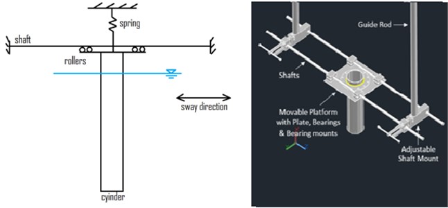
In order to estimate the dynamic performance of Vortex induced vibration of a vertically mounted cylinder, a relatively simple scaled model is fabricated and tested to evaluate the fluid-structure oscillator interaction. All the tests are conducted in the towing tank of 82×3.2×2.8 m depth. Reynolds number of this test ranges from 25000 to 150000, for which Strouhal number has a constant value of 0.2, as shown in Fig. 1. These tests are performed by idealizing the cylinder as a single degree-of-freedom system model, which is free along lift direction. Mooring system, represented by a simple spring system of 1.6 N/mm is deployed. In all tests, test section is moved while the water remains stationary with an assumption that motion amplitude and drag forcers depend on the relative motion of water and test specimen. Transverse motion amplitude () is considered in non-dimensional units as the ratio of the amplitude in sway direction to that of the diameter of the cylinder (). Occurrence of lock-in is related to the non-dimensional reduced velocity, as given below:
Fig. 2 shows the test setup for experimental investigations. Carriage motion is in perpendicular direction with reference to figure. All the test specimens are fixed to the movable platform in the direction perpendicular to the plate surface, which keeps the specimen oriented perpendicular to the water plane. Cylinder thus remains surface-piercing, which make it movable along the direction normal to the carriage motion. Shafts are held by two adjustable mounts as shown in the figure, which are fixed to a pair of guide rods; guide rods are clamped to the carriage. Suitable diameter and thickness of the guide rods are chosen to restrict the inline motion of the specimen.
Cylinder, which has a scaled dimension of Neptune Spar, with scale ratio of 1:216 is used for study. A total length of 1080 mm includes draft of 917 mm and a clear height. Cylinder is of 101.6 mm in diameter and 2 mm thick; bottom of cylinder is sealed watertight. The test specimen is fixed to the experimental setup, which is clamped to the carriage and it is moved at a required velocity in a still water medium. Apparent flow velocity, which is kinematically identical to the current velocity, is maintained through carriage control system. In all cases, mass ratio is considered as 1. Response of the cylinder is captured by the displacement transducer while specimens are tested within the velocity range from 0.2 to 1.2 m/s at an interval of 0.02 m/s. The response in terms of amplitude ratio is captured over the chosen velocity range.
Fig. 2Experimental setup
3. VIV Suppression system
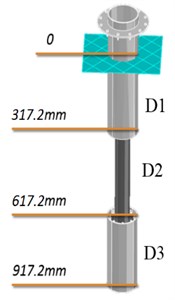
A passive method of VIV suppression is attempted. Two steel wires, as shown in Fig. 3. are attached parallel to the axis of the cylinder through a miniature turnbuckles and stretched over small notches that are cut at the ends. Sufficient tensile load is applied to keep the wire tight against the cylinder wall; no glue or other method was used to hold the wire against the cylinder. Steel wires of 0.3 mm in diameter, located at angle () with respect to the stagnation point are affixed to make wire to cylinder diameter ratio of 0.003. Tests are repeated by attaching wires at five different positions ( 40°, 50°, 60°, 70° and 80°). A parallel study is also carried out on a stepped cylinder, as shown in Fig. 4. Model is stepped with a ratio D1/D2 of 2 as shown. One-third of the total draft has external diameter (D2) 50.8 mm and remaining 2/3rd is made up of cylinder of external diameter (D1) 101.6 mm. Model is fabricated to identify the influence of abrupt change in diameter along the length on the vortex shedding frequencies along depth; it is known fact that shedding frequency is a function of cylinder diameter. With the stepped cylinder in place, at any instance of time, natural frequency of the cylinder shall synchronize with any one of the shedding frequencies. The other shedding frequencies effectively reduce the dynamic response of the system. Similar procedures in acquiring amplitude ratios are employed with stepped cylinder attached with tripping wires at 65° from the stagnation point to analyze the combined effect of both configurations.
Fig. 3Sectional view of cylinder attached with tripping wire
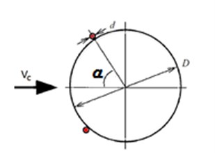
Fig. 4Stepped cylinder
4. Discussion of results
Response amplitude of bare cylinder over the reduced velocity range is compared and shown in Fig. 5. Difference in mass ratio plays a crucial role, which is evident from the discrepancy of both the curves. At lower reduced velocity, cylinder barely moves. As reduced velocity increases, lock-in phenomenon occurs and response of cylinder increases significantly. At reduced velocity of 6.668 (current velocity 0.98 m/s), maximum response occurred ( 0.87), which indicates that the cylinder undergone vibration in transverse direction with magnitude almost equal to its diameter.
Fig. 5Comparison of response
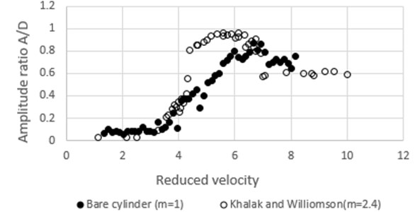
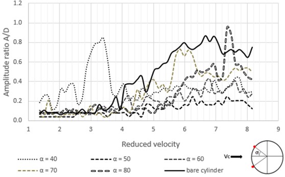
Fig. 6 shows the response behavior of bare cylinder attached with vertical wires. Promising results are achieved when tripping wires are attached at 50° from stagnation point. In this case A/D is reduced to about 71 % in comparison to that of the bare cylinder. It is also seen that under 60° arrangements, VIV suppression to a considerable extent is achieved. 40° tripping wires inhibit response at higher end of reduced velocity whereas cylinders attached with 80° tripping wires have low response at lower end of reduced velocity.
Fig. 6Response of cylinder attached with vertical tripping wires
Response amplitudes of stepped cylinder are plotted against reduced velocities and compared with amplitude ratios of that of the bare cylinder, as shown in Fig. 7. It is seen that between reduced velocities of 4 till 7, suppression of VIV is clearly evident as the peak amplitude is reduced to 0.2, after which an irregularity in the trend is observed. At reduced velocity of 8, response ratio peaked to 1.3. This unexpected increase in peak amplitudes at higher reduced velocities may be attributed to the beating phenomenon between two different shedding frequencies caused by stepped geometry of cylinder. At an instant of time, when the vortices caused by all sections along the draft length superpose in same vertical line as shown in Fig. 8, constructive interference occurs, which leads to abrupt increase in the amplitudes as observed.
Fig. 7Comparison of response
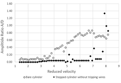
Fig. 8Constructive interference of vortices
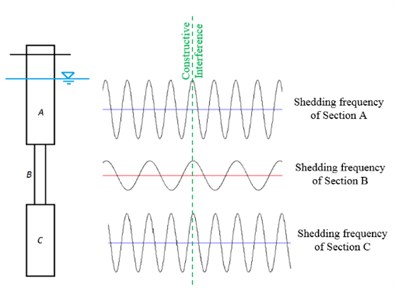
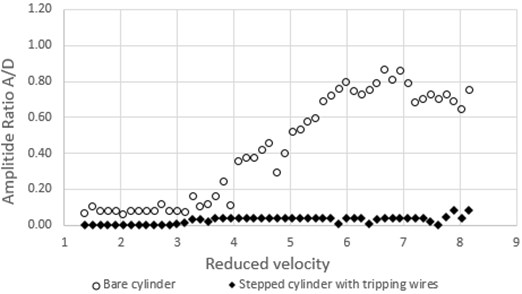
Fig. 9. shows the response of stepped cylinder attached with tripping wire compared with that of the bare cylinder. It is seen that VIV response amplitudes are effectively suppressed. Peak amplitude ratios retained values lesser than 0.1 over a wide range of reduced velocities (tested till 8.3). This might be attributed to the abrupt change in diameter along draft length of the cylinder, which is also combined with the effect of that of turbulence inside the boundary layer.
Fig. 9Comparison of response of stepped cylinder attached with tripping wire
5. Conclusions
Cylinder under steady current resulted in large response amplitude. Abrupt variation in diameter of test section along the draft, which induces turbulence within laminar boundary layer has a significant impact on the transverse responses. Experimental study confirms the effectiveness of tripping wires in VIV suppression. When wires are arranged vertically, separation point of vortices played an important role in vibration of cylinder. As angle between wires with respect to that of the stagnation point increases, lock-in point is shifted towards higher reduced velocity. Variation of diameter for 1/3rd of draft resulted in VIV suppression till the reduced velocity of 7. Sudden response at reduced velocities above 7 might be due to the constructive interference between vortices. Further tests should be conducted at higher reduced velocities to obtain longer oscillation time series to understand the physical phenomenon behind the anomaly. Maximum Response reduction of about 90 % in comparison with that of the bare cylinder is observed with geometric variation under turbulent regime.
References
-
Srinivasan Chandrasekaran, Ranjani R., Kumar Deepak Response control of tension leg platform with passive damper: experimental investigations. Ships and Offshore Structures, Doi: 10.1080/17445302.2015.1119666, 2015.
-
Srinivasan Chandrasekaran, Madhavi N. Design aids for offshore structures with perforated members. Ship and Offshore Structures, Vol. 10, Issue 2, 2015, p. 183-203.
-
Srinivasan Chandrasekaran, Madhavi N. Retrofitting of offshore cylindrical structures with different geometrical configuration of perforated outer cover. International Journal of Shipbuilding Progress, Vol. 62, Issues 1-2, 2015, p. 43-56.
-
Srinivasan Chandrasekaran, Madhavi N. Flow field around an outer perforated circular cylinder under regular waves: numerical study. International Journal of Marine System and Ocean Technology, Doi: 10.1007/s40868-015-0008-1, 2015.
-
Srinivasan Chandrasekaran, Madhavi N. Numerical study on geometrical configurations of perforated cylindrical structures. Journal of Performance of Constructional Facilities, ASCE, Vol. 30, Issue 1, 2014, p. 04014185.
-
Srinivasan Chandrasekaran, Madavi N. Retrofitting of offshore structural member using perforated cylinders. SFA Newsletter, Vol. 13, 2014, p. 10-11.
-
Srinivasan Chandrasekaran, Madhavi N. Hydrodynamic performance of retrofitted structural member under regular waves. International Journal of Forensic Engineering, Inder Science, Vol. 2, Issue 2, 2014, p. 100-121.
-
Sarpkaya T. Fluid forces on oscillating cylinders. ASCE Journal of Waterway Port Coastal Ocean Division, Vol. 104, 1978, p. 275-290.
-
Bearman P. W. Vortex shedding from oscillating bluff bodies. Annual Review of Fluid Mechanics, Vol. 16, 1984, p. 195-222.
-
Igarashi T. Flow Characteristics around a circular cylinder with a slit. Bulletin of the Japan Society of Mechanical Engineers, Vol. 21, 1978, p. 656-664.
-
Niemann H. J., Holscher N. A review of recent experiments on the flow past circular cylinders. Journal of Wind Engineering and Industrial Aerodynamics, Vol. 33, 1990, p. 197-209.
-
Blevins R. D. Flow Induced Vibration, 2nd Edition. Krieger Publishing, Malabar, FL, 1994.
-
Lesage F., Garthshore L. S. A method of reducing drag and fluctuating side force on bluff bodies. Journal of Wind Engineering and Industrial Aerodynamics, Vol. 25, 1987, p. 229-245.
-
Khalak A., Williamson C. H. K. Motions, forces and mode transitions in vortex induced vibrations at low mass-damping. Journal of Fluids and Structures Vol. 13, 1991, p. 813-851.
-
Zdravkovich M. M. Review and classification of various aerodynamic and hydrodynamic means for suppressing vortex shedding. Journal of Wind Engineering and Industrial Aerodynamics, Vol. 7, 1981, p. 145-189.
-
Owen J. C., Brankovic Masa Experimental studies of passive control of vortex-induced vibration. Journal of Fluids and Structures, Vol. 15, 2003, p. 597-605.
