Abstract
From the very beginning of the piston dynamic behavior investigation, the engineers tended to use experimental methods and compare them with very simple calculations. However, the experimental tests did show some serious difficulties that needed to be managed in order to obtain reasonable results, e.g. separation of vibrations due to piston slap motion, signal destroyed by combustion process, etc. This is the reason why the test rigs were hardly able to provide detailed insights into the piston dynamics, since it could be lost in a plethora of interactive physical phenomena. Therefore, the focus was, gradually, aimed at the computational models, which were (and still are) much faster, but need to be compared with experimental results to ensure the adequacy of algorithms used. This paper discusses the difficulties and uncertainties occurring during the construction of such computational model.
1. Introduction
The legislation of the European Union on the internal combustion engines is forcing automotive manufacturers to develop their products to be more and more advanced. Low friction loss has been the main concern for over several decades. There has already been a lot effort invested into the reduction of mechanical loss and manufacturers are dependent on optimization of every contributor of this loss. The piston group is responsible for the biggest portion of mechanical loss in internal combustion engines, up to 40 % of total engine friction [1, 2]. The piston induced noise reduction is currently more related to customer annoyance and subjective complaints than to meet legislation limits [3], but this can be easily changed with the introduction of new legislation limits.
To be able to evolve the piston to reach a design excellence, it is inevitable to have the feedback loop. Feedback provided by experimental methods is very time consuming and often very expensive. Therefore, the more suitable computational simulations are preferred. Nevertheless, experimental verifications are still mandatory to verify the final design proposal before serial production.
2. Computational model
Numerous computational models have been developed so far, but only few of them can be directly used in the automotive industry, e.g. [4]. Even when the computational tool can be used by design engineers thanks to its user-friendly interface, users are dependent on the developers of the company providing software if there is a need of implementation of some additional physics. This is the main reason why the Multibody Dynamics (MBD) software, namely MSC Adams, was used for the dynamics solution of piston/liner model. It is a well-known and very popular software among the engineers. However, to simulate piston/liner interaction correctly, MBD has to be augmented by user-written subroutines considering special phenomenon typical for piston operation cycle like:
• piston and liner true shape,
• different lubrication regimes (hydrodynamic, mixed, boundary),
• elastic deformation of piston and liner.
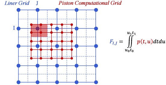
2.1. Mapping
The computational grid of contact forces between piston and liner is fixed to the piston body – let us call it piston computational grid. The piston is performing reciprocating motion relative to the liner. The contact forces calculated on piston computational grid are function of gap between piston and liner, which is dependent on the liner deformation and true shape – it has to be mapped onto the piston computational grid. To do so, bicubic Hermite spline is employed:
where is the target function; and are Hermite functions; are the source function values; , , are derivatives in , and direction. Function is continuous through the second derivative, so the deformation shape can be mapped very smoothly.
As the deformation of the liner has to be mapped onto piston computational grid, forces of piston computational grid have to be mapped onto the liner grid as well. In this case, situation slightly differs. Calculated forces result in the overall forces and moments in each direction. Load applied onto the liner is a reaction of the piston load. Therefore, the overall forces and moments acting on piston computational grid should be equal to the overall forces and moments acting on the liner grid. To fulfill this static equivalence condition, different approach of mapping was used. First of all, discrete field of pressures calculated on the piston computational grid has to be reconstructed to the analytical form:
where is the target function, are the source function values and are shape functions. To obtain nodal forces acting in the liner grid, function has to be analytically integrated in a boundaries of a dual grid of a corresponding liner grid node, evident in Fig. 1.
Fig. 1Load mapping by analytical integration
2.2. Elastic deformation and Jacobian evaluation
Elastic deformations have significant impact on the piston dynamic behavior [5]. MBD uses Component Modes Synthesis in order to obtain elastic deformations of each flexible body – the overall deformation is a linear combination of mode shapes multiplied by the modal factors. Number of modal factors is the same as the mode shape count, which is related to the reduced number of degrees of freedom (DOF). In case of flexible piston with flexible piston skirt nodes of count, there are additional (radial in case of piston and liner) DOFs introduced into the simulation.
2.3. CPU time analysis
MBD solves equation of motion by numerical integrator based on, e.g. Newmark or HHT method. In this procedure, the Jacobian has to be evaluated for each iteration. Jacobian represents the dependency of function on each DOF. In practice, if there is DOF of count, solver has to be called times to evaluate each partial derivative. This is the main cause of very time-demanding piston/liner simulations developed by the authors.
User-written subroutine, which uses deformation inputs given by the MBD solver and gives outputs of force reactions back to the MBD solver, is called every time when each Jacobian cell needs to be evaluated. For instance, subroutine consists of its own hydrodynamic iterative solver, which takes approximately 200 iterations to converge. If the computational model has 1000 DOFs, there is at least 200 000 iterations of hydrodynamic pressure calculation for each MBD solver iteration. This causes very slow computing speeds and it is a serious issue to be solved.
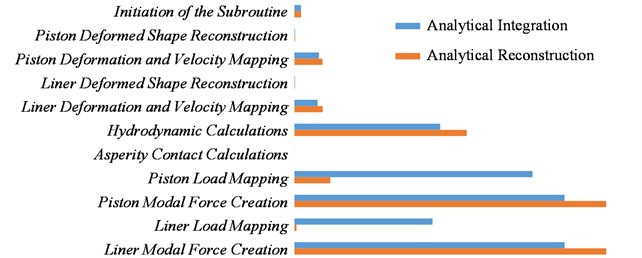
As mentioned above, user-written subroutine is called very often. Therefore, only a slight improvement in the subroutine speed would lead to faster solution times. Looking at the CPU time of hydrodynamic (elastic deformation of piston and liner not considered) analysis with load mapping using analytical integration (blue bars in Fig. 2), it is clear that the load mapping requires the second highest computational times. Therefore, a different approach is proposed – instead of integrating source pressure distribution take its function value at coordinates of target node. One has to be very careful here. Since the static equivalence between source and target of load mapping does not hold anymore, the solver is more unstable – more iterations are needed for converged solution, as it can be seen in the Fig. 2.
If the load mapping by analytical reconstruction is applied in a case of different piston computational grid for lubrication and for deformation, the situation becomes more serious. MBD solver is struggling to converge due to mapping errors. When the overall forces and moments (rigid parts of modal force) from the piston/liner contact are calculated from the source pressure distribution, MBD solver converges successfully once again.
Enabling the deformation of piston and liner changes the biggest contributors of computational time to Piston/Liner Deformed shape Reconstruction (84 % of overall CPU time). More effective approaches to reconstruct piston and liner deformed shape need to be found. Parallel computations could be very helpful, but MBD solver is currently not able to use such technique.
Fig. 2Computational time gain omitting analytical integration during load mapping
2.4. Boundary conditions – oil film height
The text above presents the difficulties in current computational simulation of piston/liner interaction. But what about uncertainties? They can be associated with boundary conditions given to the simulation as an input. Piston and liner true shape (due to the load and temperature) is affecting the piston dynamic behavior very significantly, but these deflections are very hard to obtain, because most of the time they have to be measured in a firing engine.
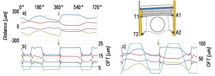
Another source of doubts can be found in the oil film thickness (OFT). What is the oil film thickness distributed to the piston skirt? Fig. 3 compares the piston secondary motion in a case of fully-flooded model, 6 μm model (constant OFT of 6 μm) and hybrid model (in upstroke OFT left by oil-control ring, during downstroke fully-flooded conditions). Offner et al. [6] performed measurements which support the theory of hybrid model of OFT.
Fig. 3Piston secondary motion: a) fully-flooded model, b) 6 μm model, c) hybrid model
3. Conclusions
Two types of issues, occurring during the development of computational model of piston/liner interaction, have been presented. One is a concern of the computational speed. From the essence of the MBD solver, it is hard to overcome. Solution may be found in the subroutine efficiency optimization (fast mapping algorithm) and sensitivity analysis of piston dynamic behavior (some minor phenomena may be neglected).
Another issue is the boundary conditions used in the simulation. Since the piston has to withstand extreme loading, it is demanding to carry out experimental attempts with reasonable results. This paper has shown one of these situation – question of oil film thickness between the piston and liner, which strongly affects the piston’s secondary motion.
References
-
Patton K., Nitschke R., Heywood J. Development and evaluation of a friction model for spark-ignition engines. SAE Technical Paper 890836, 1989.
-
Hoppe S., Mittler R., Dörnenburg T. H., Meske R. Contribution of advanced piston and ring design and coatings on friction reduction in future diesel engines. 22nd Aachen Colloquium Automobile and Engine Technology, Aachen, 2013.
-
Offner G., Priebsch H. Elastic body contact simulation for predicting piston slap induced noise in IC engines. 2nd Triennial Intern Symposium Multi-body Dynamics, Bradford, 2000.
-
Knoll G., Bargende M., Lang J., Philipp U., Lazzara M. Piston pin in mixed friction contact elasto-hydrodynamic simulation theory for support analysis. MTZ Worldwide, Vol. 70, Issue 4, 2009, p. 54-60.
-
Oh K. L., Li C. H., Goenka P. K. Elastohydrodynamic lubrication of piston skirts. ASME Journal of Tribology, Vol. 109, 1987.
-
Offner G., Herbst H., Priebsch H. A methodology to simulate piston secondary movement under lubricated contact conditions. SAE Technical Paper 2001-01-0565, 2001.
About this article

The research leading to these results has received funding from the Ministry of Education, Youth and Sports under the National Sustainability Programme I (Project LO1202) and the Faculty of Mechanical Engineering of Brno University of Technology under Project Fund of Science FME 2016, Project No. FV 16-39.
