Abstract
According to the high stiffness requirement of bearings on spindle systems of precision machine tools, a kind of compound bearing composed of tilting pads and rolling bearing is proposed in this paper. In the start and stop process, the weight of rotor parts is borne by the rolling bearing, and the tilting pads avoid wear. When the spindle is reaching a certain speed, the rolling elements is disengaged from the outer ring of the rolling bearing, and the load is carried by the tilting pad bearing alone. The pivot position of the tilting pads can be defined by two characteristic parameters: Radial Pivot Position Coefficient (RPPC) and Circumferential Pivot Position Coefficient (CPPC). The influence laws of the pivot position parameters on the performance of compound bearing are synthetically analyzed. The results show that the stiffness of compound bearing can be effectively improved by proper design of the two pivot position parameters. The theoretical researches on this new compound bearing in this paper provide reference for bearing design of high stiffness spindle system.
1. Introduction
On account of the features of high stiffness and zero wear in the working state, the sliding bearings replace the rolling bearings to be the bearing of spindle or motorized spindle on high speed and precision machine tools [1]. The hydrostatic bearings and hybrid bearings float the spindle by static pressure in low speed, and the hydrodynamic effects in high speed make the bearing possessing high load carrying capacity and stiffness [2]. So they are most widely used, and scholars at home and abroad have done a long term research [3]. The related technologies are relatively mature. However, the oil supply systems of hydrostatic and hybrid bearings are complicated and have high energy consumption. Restrictors with small hole or slit are generally used as the compensating elements, which reduces the reliability of the system [4]. Moreover, for the spindle systems on precision machine tools, high oil pressure and more oil flow are needed to satisfy the high bearing stiffness requirement [5].
In contrast, hydrodynamic bearings have much lower requirements for oil supply system, and have been used in some spindle systems with low precision requirements [6]. In order to solve this problem, many scholars make diverse efforts. Lu [7] have conducted theoretical and experimental research on compound bearing of rolling bearing and sliding bearing. It is proved that the weight of rotor parts is borne by the rolling bearing in the start and stop phases through the proper design of parameters, and the load is carried by the tilting pad bearing alone after a disengagement process of rolling bearing when the speed is up to a certain stage. Circular journal bearings are used in this compound bearing, and there will be not easy to satisfy much higher stiffness. Zhang [8] and Chen [9] introduce the hydrostatic pressure into the tilting pad bearings. The technical feasibility is theoretically analyzed and then the design, manufacture and verification test of the hybrid tilting-pad bearing is carried out. But this coupled structure of tilting-pad and hydrostatic pressure causes the uncertainty of performance and stability problem in high pressure of oil supply, so this bearing has almost no application in practice.
With the development of the machine tool towards efficiency and precision, especially for the high precision grinder (the rotation accuracy is 0.1 μm), the requirements of the spindle system stiffness that is higher than 800-1000 N/μm are put forward. Therefore, the tilting pad technology is introduced into the compound bearing system in this paper, and a kind of compound bearing composed of tilting pads and rolling bearing is proposed. In the start and stop process, the weight of rotor parts is borne by the rolling bearing, and the tilting pads avoid wear with the contact of rotor. Under the working speed, the requirements of lubrication and dynamic performance on spindles are met through the proper design of the pivot positions of the tilting pads.
2. Typical structure of compound bearing
The compound bearing includes a pair of four-pad tilting pad bearing and a pair of rolling bearing. The four bearings are arranged side by side, and collectively constitute the bearing system of the spindle. The typical structure is shown in figure 1. The outer ring of rolling bearing is fixed by magnets. The balls keep their relative positions to the outer ring by the cage. The inner ring and the rotor is interference fit. The radial clearance of the rolling bearing is smaller than the diameter installation clearance of the tilting pad bearing (the definition shows in Section 3.1). So the inner ring is in contact with the balls to undertake all the load at lower speed, and the tilting pads are not contact with the rotor as shown in Fig. 1(a). In high speed, the tilting pad bearing floats the rotor, and the inner ring is off the balls as shown in Fig. 1(b).
Fig. 1Compound bearing of tilting pad bearing and rolling bearing: a) in low speed, and b) in high speed
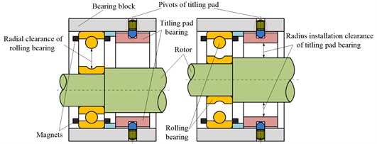
Table 1Structure parameters and operating conditions of tilting pad bearing
Physical quantity | Symbol | Unit | Value |
Diameter of tilting pad bearing | mm | 100 | |
Width of tilting pads | mm | 70 | |
Number of pads | 4 | ||
Machine gap of tilting pads | μm | 30 (initial value) | |
Installation clearance of tilting pads | μm | 30 (initial value) | |
Wrap angle of tilting pad | ° | 60 | |
Wrap angle from the inlet side to the pivot | ° | 30 (initial value) | |
Rated load | N | 400 | |
Rated speed | r/min | 10000 | |
Range of working speed | r/min | 8000-12000 | |
Dynamic viscosity | Pa∙s | 0.00187 | |
Density | kg/m3 | 850 | |
Specific heat capacity | J/(kg∙°C) | 2100 |
3. Analysis on static and dynamic characteristics
3.1. Basic parameters of an example
The structural style of tilting pad bearing in this paper is four cavities symmetrically arranged. The typical structure is shown in Fig. 2, and the parameters of bearing structure and operating conditions are shown in Table 1. The identification code of rolling bearing is 6216C3, the internal diameter is 80 mm, and the range of radial clearance is from 25 μm to 51 μm. In this paper, is 30 μm.
It is important to note that , which is defined as installation clearance (in μm), and is related to the pivot position of tilting pad after installation. The pivot is in the center of the surface of tilting pad, and the pivots of four tilting pads are in a circle, which is called pivot circle. is the radius of pivot circle. is the radius of shaft.
, which is defined as machining clearance (in μm), and is related to the curvature radius of tilting pad surface during processing. is the curvature radius of tilting pad working surface.
Fig. 2Structure of four-pad tilting pad bearing
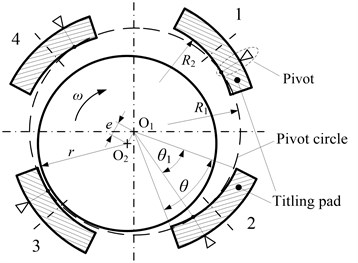
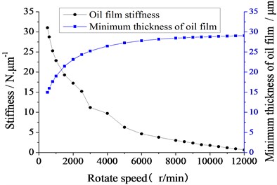
Fig. 3Changing curves of the minimum thickness of oil film and the stiffness on the speed
3.2. Static and dynamic characteristics of tilting pad bearing
For the compound bearing, the research of runtime performance focuses on the minimum thickness of oil film and the stiffness of the tilting pad bearing. The bearing stiffness especially in the range of working speed, has direct effect on the running accuracy of the spindle system. The Reynolds Equation is as follow:
where, is the circumferential speed of the journal, and is the lubricating oil viscosity. is the oil film pressure, which can be solved numerically by Finite Difference Method (FDM). Then the static and dynamic characteristics can be acquired, including oil film thickness and stiffness.
In the speed range of 500 r/min to 12000 r/min, the changing curves of the minimum thickness of oil film and the stiffness on the speed are shown in Fig. 3.
Under the condition of constant load, the minimum thickness of oil film is increasing with the increasing of speed, and it is greater than 15 μm in the range of working speed, which shows that the bearing has good lubrication performance. While the oil film stiffness of tilting pad bearing is gradually reduced. The stiffness is even less than 5 N/μm, which is at least two orders of magnitude lower than the stiffness requirement of bearing system on precision machine tools (≥ 1000 N/μm). Obviously, the stiffness of tilting pad bearing needs to be improved. Under the condition that the size and basic structure of tilting pad bearing cannot be easily changed, adjusting the pivot position is an effective method to enhance the stiffness of tilting pad bearing.
4. Impact analysis of pivot position of tilting pad on compound bearing performance
4.1. Two parameters characterization of the pivot position of tilting pad
The pivot position of tilting pad bearing has a great impact on its static and dynamic characteristics, especially the stiffness and minimum thickness of oil film, which is of concern in the high speed and precision machine tools. Referring to the typical structure of four-pad tilting pad bearing (Fig. 2), two parameters are needed to characterize the radial and circumferential positions of the tilting pads, and the pivot positions of tilting pads relative to the axle journal is confirmed.
The characterization parameters of pivot position of tilting pad defined in this paper are:
where is the Radial Pivot Position Coefficient (RPPC), which is called preload coefficient in some researches [10]. The calculation formula is as follows:
is the Circumferential Pivot Position Coefficient (CPPC), which is called pivot ratio by some scholars [11]. The calculation formula is as follows:
where is the wrap angle of tilting pad, is the wrap angle from the inlet side to the pivot. The meanings of other symbols are similar.
4.2. Impact of pivot position on compound bearing performance
In Eq. (3), the value of RPPC is relevant to the installation clearance and machining gap. So there are two approaches to adjust the RPPC and improve the performance of bearing: 1) Method of Constant Machining-gap (MCM). The radius of curvature of tilting pad surface is kept constant, and different RPPCs are obtained by changing the installation clearance. 2) Method of Constant Installation-clearance (MCI). The pivot installation position of the tilting pad bearing is kept constant, and RPPCs are transformed by different radii of curvature of tilting pad surface in processing.
4.2.1. Impact analysis of pivot position under MCM
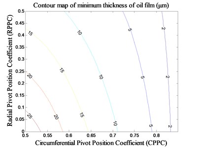
The radius of curvature of tilting pad surface is constant under MCM, and the machine gap of tilting pads is 30 μm. Then the value range of RPPC is 0-0.5, considering that the radial clearance of rolling bearing is 30 μm, which should be smaller than the diameter installation clearance of the tilting pad bearing. The value range of CPPC is 0.5-0.85. Then the stiffness and minimum thickness of oil film of tilting pad bearing under the rated speed (10000 r/min) is obtained with the different pivot positions, which are shown in Fig. 4 and Fig. 5.
The stiffness of tilting pad bearing increases rapidly when the RPPC is increased under MCM. The stiffness around the area A is even higher than 6000 N/μm, and the stiffness can increase to infinity if the RPPC tends to 1. The stiffness decreases at first and then increases with the increasing of the CPPC, and the value of CPPC corresponding to the minimum stiffness is in the region of 0.76. The minimum thickness of oil film of tilting pad bearing all decreases gradually with the increasing of the two pivot position parameters. In contrast with the RPPC, the effect of CPPC is more apparent. With the proper design of the two pivot position parameters under MCM, ultra-high stiffness is possible when satisfying a certain requirement of minimum thickness of oil film. That is applicable to spindle systems of light-load, high-speed and ultra-precision machine tools.
Fig. 4Impact of pivot position on stiffness under MCM
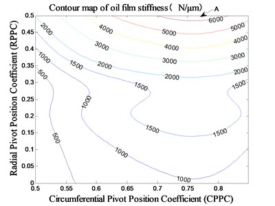
Fig. 5Impact of pivot position on minimum thickness of oil film under MCM
4.2.2. Impact analysis of pivot position under MCI
The radius installation clearance of tilting pads surface is constant 30 μm. Then the value range of RPPC is 0-1 by changing the radial of curvature of tilting pad surface. The value range of CPPC is still 0.5-0.85. Then the stiffness and minimum thickness of oil film of tilting pad bearing under the rated speed (10000 r/min) is obtained when the pivot positions are different, that is shown in Fig. 6 and Fig 7.
Fig. 6The impact of pivot position on stiffness under MCI
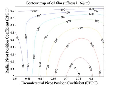
Fig. 7The impact of pivot position on minimum thickness of oil film under MCI
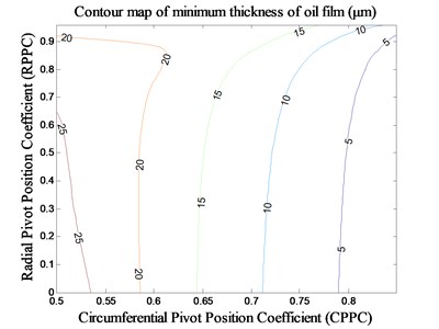
The stiffness of tilting pad bearing is also improved when the RPPC is adjusted under MCI, of which the highest stiffness value is about 1000 N/μm, indicated by A in Fig. 8. When the CPPC is small (about 0.5-0.55), the stiffness increases at first and then decreases with the increasing of the RPPC. When the RPPC is in the range of 0-0.8, the stiffness increases at first and then decreases with the increasing of the CRPPC, and the value of CPPC corresponding to the stiffness peaks is nearby 0.76. The variation trend of minimum thickness of oil film of tilting pad bearing is roughly identical to that under MCM, which is also decreases gradually with the increasing of the two pivot position parameters and is predominantly affected by CPPC.
In contrast with the MCM, the enhancive stiffness of tilting pad bearing under MCI is limited to about 1/6-1/8 of that under MCM. But the decrease tend of minimum thickness of oil film is slowing down. Therefore, the bearing stiffness can be effectively improved on the premise of greater oil film thickness with the proper design of the two pivot position parameters under MCI. That is applicable to the spindle systems of moderate-load, medium-speed and precision machine tools.
5. Conclusions
1) A kind of compound bearing composed of tilting pads and rolling bearing is proposed. The weight of rotor parts is borne by the rolling bearing in the start and stop process. Under the working speed, the load is carried by the tilting pad bearing alone. The requirements of lubrication performance and high stiffness on spindle systems of high speed and precision machine tools are met through the proper design of the pivot position of tilting pads.
2) The static and dynamic characteristics of tilting pad bearing are analyzed in different speeds, and it is indicated that the performance of the compound bearing can be improved if adjusting the pivot position of the tilting pads.
3) The pivot position of tilting pad bearing is defined by two characteristic parameters, and the methods of adjusting the RPPC by two controlling parameters of installation clearance and machining gap are given. The influence laws of the two pivot position parameters on the performance of compound bearing are synthetically analyzed, such as stiffness.
4) The results show that the stiffness of compound bearing can be effectively improved by proper design of the two pivot position coefficients. If adjusting the RPPC under MCM, a ultra-high stiffness of compound bearing can be obtained. But the limit of minimum thickness of oil film should be considered. While the stiffness of compound bearing can be effectively improved by adjusting the RPPC under MCI. But the enhancive stiffness of tilting pad bearing under MCI is limited.
References
-
Ding Z. Q. Liquid hydrostatic and hybrid technique developing history and present situation in China. World Manufacturing Engineering and Market, Issue 2, 2014, p. 73-76.
-
Xiong W. L., Yang X. B., Lv L., Yuan J. L. Review on key technology of hydrodynamic and hydrostatic high-frequency motor spindles. Journal of Mechanical Engineering, Vol. 45, Issue 9, 2009, p. 1-18.
-
Zhang G. Y., Yuan X. Y., Miao X. S., Li Z. G., Li C. H. Experiment for water-lubricated high-speed hydrostatic journal bearings. Tribology, Vol. 26, Issue 3, 2006, p. 238-241.
-
Chen C. H., Kang Y., Chang Y. P., Wang Y. P., Lee H. H. Influence of restrictor on stability of the rigid rotor-hybrid bearing system. Journal of Sound and Vibration, Vol. 297, Issues 3-5, 2006, p. 635-648.
-
Wu H. C., Fu H. X., Li J. X., Zhang H. J., Wang L. J. Development of oil supply hydraulic system of hydrodynamic/hydrostatic bearing in the spindle system of high speed roller grinding machine. Chinese Hydraulics and Pneumatics, Issue 5, 2011, p. 42-44.
-
Wu H. C., Wu C. C., Zhang H. J., Li J. X., Liu H. B. Application of liquid sliding bearing in roll grinder. Coal Mine Machinery, Issue 6, 2011, p. 203-205.
-
Lu D., Zhao W. H., Lu B. H., Zhang J. Static characteristic of a new hydrodynamic-rolling hybrid bearing. Tribology International, Vol. 48, 2012, p. 87-92.
-
Zhang G. F. Research on the Behavior of Hybrid Tilting-pad Journal Bearings. Xi’an Jiaotong University, Xi’an, 1989.
-
Chen J. L. The Experimental Study of the Behavior for Hybrid Tilting-pad Bearing. Xi’an Jiaotong University, Xi’an, 1992.
-
He G. A., Chang Y., Zhang X. Y., Tang R. Z. Application of preload factor to eliminating unstable vibration of tilting pad bearings. Electric Power, Issue 11, 2012, p. 36-40.
-
Xu L. X., Zhu J., Yu L. A study on stability of rotor systems supported by tilting-pad bearings. Chinese Journal of Applied Mechanics, Vol. 4, Issue 3, 1987, p. 57-68.
About this article

This work is supported by the National Natural Science Foundation of China (Grant No. 51275395) and the National Science and Technology Major Project of China (No. 2012ZX04002-091).
