Abstract
This article contains the analysis of tube expander dynamics in complex interaction of structural elements of heat-exchange tubes attachment assembly in the process of roll-forming operation, description of dynamic process theoretical aspect. It is shown that torque variations lead to velocity fluctuations and influences the service life of operative parts of tube expander and quality of tube attachment assemblies.
1. Introduction
In the state-of-the-art power, oil refining and chemical industries the devices in which attachment of heat-exchange tubes is carried out by means of their ends expansion using mechanical roll-forming are widely spread.
Despite the significant (almost century old) acquired experience of roller expanders usage, in many cases any change of tube or roller tool parameters lead to unexpected negative results – unacceptable peeling of tube inner surface, violation of joint tightness, fast wear of the tool, etc. Moreover, the properties, representing the violation of tube attachment quality in many cases are revealed during the installation of heat-exchange unit at site and even in the process of its operation. It witnesses about insufficient study of the process and requires the new approaches and methods of research for dynamic elastic plastic processes in the areas of process influencing.
Currently manufacturing of heat-exchange power equipment is relied on the normative documentation which was developed even in the last century. It formed the basis of the methodology of the earlier performed researches with the accepted major assumptions [1-3]. On their basis the roll-forming process is considered as the convergence of two almost concentric surfaces of the tube and the orifice in tube sheet with the further compression. This approach is correct for the processes of hydraulic or press expansion. In case of roll-forming it is necessary to emphasize several peculiarities which are not to full extent in compliance with this point of view and require the carrying out of additional researches of such processes as:
– plastic deformation of the tube by taper rollers, which rotation axis does not coincide with the tube axis;
– contact interaction of taper rollers and the surface of the tube being distorted;
– the operation dynamics of roller expander working part, especially at long length of the tool and irregularity of its position as well as in cases of usage of different types of actuators.
In case of roll-forming tube deformation originates due to tube bending in the point of its contact with the rollers and further plastic change of dimensions.
Ordinarily roll-forming is considered in terms of static process. In such case the contact of the rollers with the tube could be analyzed using the solutions indicated in works [4-8].
Actually in this case occur fluctuations with different amplitude and frequency influencing both the tool efficiency and the quality of tube attachment during the fabrication and repair of heat-exchange units. Therefore, the lack of publications concerning this subject matter the present work describes the peculiarities of roll-forming dynamics.
1.1. Special aspects of roll-forming process
Roll-forming process is to be considered including variable interactions of contacting surfaces in each loading point cumulatively with contact assignment. The scheme of roll-forming is given at Fig. 1.
Fig. 1Scheme of roll-forming of tube attachment assembly into the tube sheet: 1 – roller, 2 – body, 3 – spindle, 4 – race, 5 – rolling bearing, 6 – shank end, 7 – tube sheet, tube
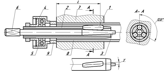
Tight connection of the tube with orifice surface of the tube sheet is provided by the torque of the spindle (3) and the indentation of the roller (1) in some neighborhood of contact point of the tube (8) and the roller. In the roller action area tube metal became soft when the part of the layers moves in the line of roller surface motion, and the other part is expanded and compressed sealed against the orifice wall [9]. Let us remark that the body (2), where the rollers are placed, is rotating in one direction with the spindle, but with different frequency.
The length of roller expander body is selected based on the design of tube attachment assembly in the tube sheet and roll-forming area distance. Hence it could achieve the large dimensions. In this case body moment of inertia during its rotation increases which under certain conditions is capable to influence negatively to the roll-forming process. In case of resonance the significant tool fluctuations could appear which lead to its damage or roll-forming quality decrease.
Let us carry out the analysis of roll-forming process dynamics.
1.2. The analysis of roll-forming process dynamics
Suppose that roller expander is used for tube fastening, as shown in Fig. 1. Description of roll-forming process is represented in detail in scientific works [9, 10, 11]. Its peculiarity is that the rotating spindle is pulled in and by its conical part by means of rollers plastically deforms the tube. At the moment of the first contact of outer surface of tube section and orifice internal surface in tube sheet the contact is performed in three points. From this time deformation conditions of tube are substantially changed, especially after the moment, when the contact still exists in the indicated three points during roller shifting to the another place.
If prior to the first contact between the couple of rollers, the expansion area distance is approximately equal to 1/3 of tube circle, then in the future each roller affects the tube section, located between two closer points. Along with this as the spindle is pulled in, the length of such tube section could be step-wise reduced [9]. We accept that cylindrical cover is influenced by the effect of forces which are distributed symmetrically towards the cylinder axis.
With the purpose of research of dynamic characteristics of the process we could take the general model of inertial disk, which is rotating at the end of rod.
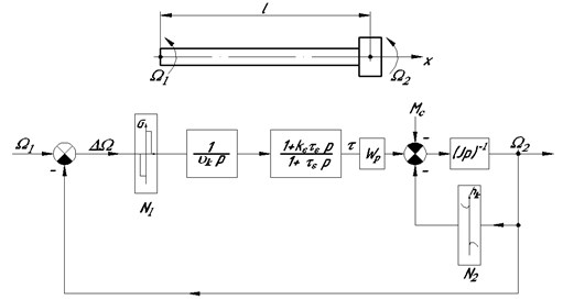
Angular velocities of rotation of spindle and shank end sections nearby the working part are to be marked as , consequently. Structural configuration of rolling movement transfer is given at Fig. 2 [12].
Fig. 2Structural configuration of rolling movement transfer: ϑk – rotating elasticity coefficient; p – differentiation operator (p=d/dt); τ – developed tangential stresses; τε – relaxation constant; kε – coefficient of correlation of adiabatic and isothermal modulus of elasticity of rod material; Mc – resulting moment of resistance forces; l – rod length with disk; hk – coefficient of friction losses
We neglect relaxation phenomena, and roll-forming system dynamics to be described by the following differential equations [12, 13]:
where – maximum tangential stresses in spindle section; – polar modulus of resistance of spindle section at shank end boundary; – torque providing tube deformaion; – moment loses due to friction; – moment of inertia of rotating elements of the tool reduced to spindle axis; – roll-forming time, – coefficient of spindle rotating elasticity determined by the ratio of .
From the solution of the system (1) after appropriate manipulations at we have the following equation of motion:
which in fact is known as the equation of forced vibrations [14].
Interaction between maximum tangential stresses in the rod, the torque and angular velocity could be described by the ratio [13]:
Here – constant in time .
So the dynamics of rolling tool vibration system depends on many parameters including: spindle torque, geometric properties of the body, the spindle and the roller, roll-forming length and parameters of roll-forming equipment. Let us consider each of them in detail.
1.3. Theoretical aspect of roll-forming process dynamics
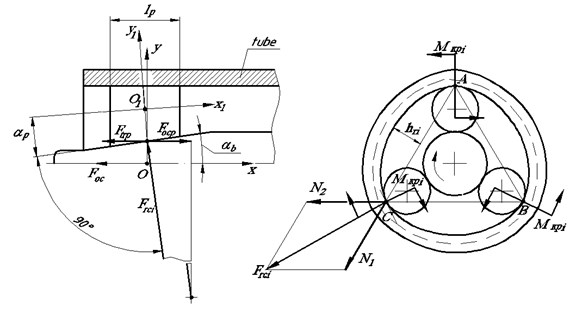
In the process of roll-forming the roller which is rotating with frequency of , is pressed to the tube by the spindle rotating around its axis with frequency of . In such case as far as the spindle penetrates into the tube force interaction between the roller and the spindle is increasing. Maximum force is , Fig. 3. As a result, during the assembly of one attachment assembly the torque of the spindle is changed from the minimum to the maximum for single roll-forming cycle [9]. Theoretical determination of the torque providing tube plastic deformation and tight connection is to be considered from the kinematics of force interaction at the point of contact of the roller with its subsequent indentation into the tube inner surface, Fig. 3.
Fig. 3Design scheme of force interaction of roller, spindle and tube
Rotation frequency of the roller relative to the body is connected with the ratio:
where – spindle rotation frequency.
Reduced moment of inertia of the system could be determined as the sum of the moment of inertia of rotating body of the roller expander and the moment of transfer couple “spindle – roller”. Intrinsic moment of inertia of the roller is to be neglected [9]. The following formulae are to be used:
Here – specific weight of body metal; , , – outer, inner diameters and body length; – transfer ratio between the roller and the body; , – mean diameters of the roller and the spindle correspondingly; – transfer ratio between the roller and the spindle.
Let us suppose that normal specific force between the roller and tube inner surface is constant along the whole contact length. As a result of interaction of elementary section with roller surface length and the tube in the plane perpendicular to spindle axis of rotation, elementary circumferential force is developing at the point of their contact which could be determined as follows:
It should be noted that the radius of roller section is a variable value along spindle length and could be determined by the function of section mean radius if axis of coordinates to be situated in the center of the roller. In such case radius value to be determined by the ratio:
As roller angle relative to the spindle is a small value ( = 1/120÷1/180), then coefficient to be accepted as equal to unity.
Taking into consideration (6) and (7) the torque developing at the roller to be as follows:
Here – coefficient of friction between the tube and the roller; – contact length.
Whence it follows that circumferential force on roller surfaces and perpendicular to equals to:
Force perpendicular to roller axis to be determined as per the formula:
In the process of hypocycloidal rolling of tube inner surface rollers push it in the opposite direction with the force of:
Suppose that the roller completely bears against the spindle surface and specific normal load to the generated between the roller and the spindle is constant along the whole contact length, the following ratios to be noted:
– torque developed by operating (tapered) element of the spindle:
– power for roller expander operation:
Here – mean reference radius of spindle operating element varied as far as the spindle penetrates into the tube.
Thus all force factors are determined. Taking this into consideration final formulae for calculation of forces on each roller to be given as follows:
– radial force:
– circumferential force along outer diameter:
– axial force:
Here – coefficient considering irregularity of load distribution between the rollers. Reduced formulae have practical confirmation [9].
As forces involved in the process of roll-forming depend on the torque and roller expander parameters, then according to the equation (2) arise frequency variations of spindle and roller rotation, which have significant effect on manufacturing quality of tube attachment assembly.
Fig. 4 shows experimental oscillograph trace of roll-forming process of tube Ø16×1.4 of steel 08Х18Н10Т in lodgment with hole Ø16.4 mm at = 4.4 Nm, = 400 r/min by means of roller expander.
Fig. 4Oscillograph trace of mechanical roll-forming: 1 – spindle axial displacement, mm; 2 – number of spindle rotations (nk), r; 3 – number of rotations of roller expander body (n0), r; 4 – torque at roll-forming (Mkp), dNm
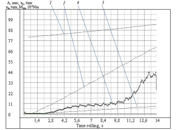
The results of the experiment show that spindle rotation is followed by regular torque variations. Approximate number of such variations is equal to spindle rotation number, and amplitude after some damping is (0.15...0.20) . Probable cause of such variations is slipping of the roller relative to the tube [9].
It is to be noted that the indicated amplitude of variations is obtained after the damping in strain gauge of test bench. Such variations especially at significant axial loads have a detectable effect on device service life and roll-forming quality.
2. Conclusion
Experimental and analytical researches show that all the elements of roller expander are influenced by variable forces which at continuous treatment of thousands of holes (for instance, in HPH plates) have an effect on roller expander efficiency. Under the certain conditions failure of the spindle, rollers, the body caused by fatigue stresses could take place. Such failure at manufacturing of the critical product is exceptionally undesirable as it causes damage of tube inner surfaces with their further probable corrosion. Furthermore, torque variations lead to velocity variations of the rollers provided an effect on stress condition of elements of tube attachment assembly.
References
-
Tkachenko G. P., Brif V. M. Manufacturing and Repair of Shell-And-Tube Heat-Exchange Equipment. Machine-Building, Moscow, 1980.
-
Yuzik S. I. Tube Expanding in Ship Heat Exchangers. Shipbuilding, Leningrad, 1978.
-
Novokshchnov S. L. Mathematical modelling of roll-forming processes. Transactions of the 8th All-Russian with International Engagement Scientific and Technical Conference and School of Young Scientists, Postgraduate Students and Students, Voronezh, 2007, p. 89-92.
-
Johnson K. L. Contact Mechanics. Mir, Moscow,1989.
-
Bulanov E. A. Universal relationship between deformation parameters and load at elastic plastic ball indentor penetration into the elastic half-space. Problems of Machine-Building and Machine Reliability, Vol. 1, 2009, p. 25-29.
-
Koteneva N. V. Elastic plastic contact of smooth sphere with flat surface at dynamic loading. Bulletin of Altai STU, Vol. 308, Issue 2, 2005, p. 115-119.
-
Nadai A. L. Plasticity. ONTI, 1936.
-
Kolesnikov K. S. Machine-Building. Encyclopedia. Т.I-3. Book 1. Dynamics and Strength of Machines. Theory of Mechanisms and Machines, 1994, p. 533.
-
Kondratenko L. A. Roll-Forming of Heat-Exchange Tubes. Sputnik, Moscow, 2015.
-
Terekhov V. M., Kondratenko L. A., Vinnikov V. S. Force interactions in roller expander. Machine-Building Technology, Vol. 7, 2012, p. 24-28.
-
Kondratenko L. A. Hydrostatic model of roll-forming process for heat-exchange tubes. Machine-Building Technology, Vol. 10, 2013, p. 57-60.
-
Kondratenko L. A. Vibrations and Speed Regulation Methods of Movement of Technological Objects. MRSU, Moscow, 2005.
-
Kondratenko L. A. Calculation of Velocity Variations and Stresses in Machine Assemblies and Components. Sputnik, Moscow, 2008.
-
Yuvorsky B. M., Detlaf A. A. Physics Handbook. Science, Moscow, 1974.
About this article

