Abstract
The results of a numerical-analytic study for the dynamics of a vibro-impact mechanism with a crank vibration generator are presented in this paper. We show bifurcation diagrams and stability regions that let us find basic patterns in the reorganization of motion modes when the mechanism’s parameters change.
1. Introduction
Invention [1] and schemes of mechanism prototypes shown their present a new scheme for vibro - impact mechanism with a crank vibration generator for earth compaction in a confined area of production. The scheme contains several percussion pistons, which lets one, as noted in [1], to perform earth compaction more efficiently, while small overall dimensions let one use the mechanism in complex confined condition. A similar scheme mechanism considered in [2-6]. In [2], a mathematical model for a vibro-impact mechanism with crank vibration generator is presented together with formulas for finding the simplest periodic motions of the mechanism.
The present work is a continuation of [2] and differs in that here we take into account that the considered scheme has a support plate for each percussion piston whose levels can be controlled to tune the mechanism for a specific desired operation mode. We also give results of numerical experiments that have let us find different types of the mechanism’s motion, including stochastic ones, and find values of parameters for which known period doubling bifurcations are realized.
1.1. Problem setting
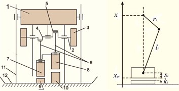
The scheme of the considered mechanism is shown on Fig. 1(a), where 1 is the mechanism’s hull in which the bearings contain an axis 2 with a fly wheel 3 and cranks 4 and 5 with radii , that have a stationary phase shift . The cranks have a joint connection to the piston rods 6 (of length ); percussion pistons 7 and 8 are, in turn, connected to them with a joint. Under the percussion pistons we have anvils 9, 10 with heights , respectively. The hull 1 has a joint connection to the racks 11 that are rigidly connected to the anvil block 12. The rotation of the axis in the proposed scheme is transformed with a crank mechanism into a back-and-forth motion with respect to the anvil block. The percussion pistons may alternate their blows to the corresponding anvils, and the vibro-impact created here is transmitted through the anvil block to the material being compacted.
Fig. 1The scheme of the considered mechanism
We denote by the coordinate of the hull’s center of mass , by ( 1, 2), coordinates of the percussion piston masses mi, and compose expressions for kinetic and potential energies presenting the Lagrange function as:
also, using obvious relations , , and assuming , 1, 2, we represent the mechanism’s motion equations as Eq. (1), (2):
where we have introduced the following notation: , , , while , are velocities immediately after and before the impact.
1.2. Solution method
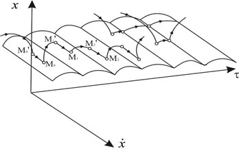
Phase space for system (, ) in coordinates , , is reduced with respect to . The surface () is a cylindrical surface formed by an intersection of two surfaces , . All phase trajectories are located either on the surface or above it. If it corresponds to free motion of the mechanism; if , it corresponds to an impact interaction of one of the pistons with the stop (anvil block). Phase trajectories are shown on Fig. 2 in a qualitative form. In case of an impact motion for the depicting point moves in the phase space as follows: moving in the region , it reaches the surface at some point and then instantaneously moves along the surface up to a certain point and then, having left , moves according Eq. (1) in until it reaches the surface again at some point . Thus, the depicting point will reach surface every time.
The class of trajectories described above corresponds to a lengthy stop of one of the pistons or to successive “trampling” of the pistons. We must note that the form of the surface shown on Fig. 2 is preserved only if surfaces and intersect.
Fig. 2The surface S
However, it is clear that impact motions of the mechanism are possible if only one of the pistons interacts with the anvil. Then the surface will be a smooth cylindrical surface with equation either or . Using equations , we can get a relation on the mechanism parameters:
Thus, the description of the phase space structure and the behavior of phase trajectories in it imply that as a section plane [7] we can take the surface and study the dynamics with the method of point maps [7, 8]. In this case, it means mappings of the section plane onto itself.
1.3. Constructing a point map
Let:
be three consecutive points that belong to the surface ; then a transformation of the points can be written as:
1.4. Existence and stability conditions for fixed points at a point map t corresponding to periodic two-impact motion modes
Equations for finding the coordinates of fixed points on a point map corresponding to two-impact periodic motions (with consecutive impacts by each percussion piston) results by adding periodicity conditions [8] to Eq. (3-5):
Resolving system Eq. (4-6) with respect to , , , , we get:
1.5. Results of numerical experiments
Our study of the mechanism’s complex dynamics has been augmented by numerical experiments that employ a software suite developed in the Borland C++ Builder 6 IDE. We denote by the existence and stability region for periodic motions in the space of parameters, where and denote the number of impacts by the first and second percussion piston against the anvil block respectively. Fig. 3 shows the bifurcation diagram built for of parameters , , , , , , , . The horizontal axis on the diagram shows the values of the frequency parameter ; the vertical axis, values of post-impact velocities Fig. 3(a) corresponds to the diagram with impacts by first piston ; Fig. 3(b), to the diagram with impacts by the second piston .
Fig. 3Bifurcation diagrams
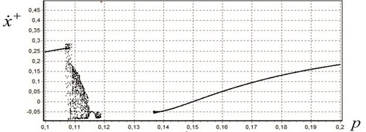
a) For the first piston
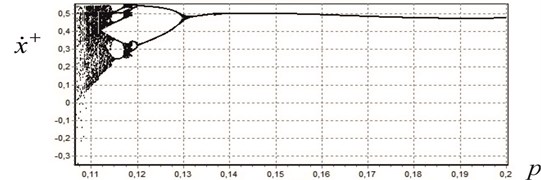
b) For the second piston
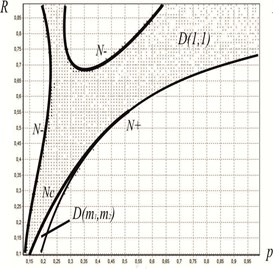
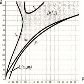
Fig. 4Areas of the existence and stability of periodic motions with alternating strokes of the pistons: a) k1=0, k2=0, b) k1=0.2, k2=0.3
a)
b)
The pictures show that for frequencies there exists a periodic motion with , ; for frequencies , periodic motion modes with 1, 0 (there occur periodic strikes by only one piston); for frequencies we observe periodic motion modes with two strikes of only one piston ( 2, ); with four (4, ) and, finally, in the interval we see a chaotic motion mode. Values of frequencies and are bifurcational since as their values increase, we see that the number of strikes by the first piston doubles (the period doubling process), which is known to lead to chaotic motion [9]. With our software suite, we performed numerous computations, in particular, constructed existence and stability regions for periodic motion modes as a function of the relative value of the supports for percussion pistons. For instance, Fig. 4(a) shows, in the plane , the region (dashed region) for the following set of parameters (without supports):
and the bifurcation boundary [8]. In the region , where and are not simultaneously equal to 1, there exist motions with several (more than two) strikes by each of the pistons. Fig. 4(b) shows the existence and stability region for the periodic motion (1, 1) for the values of parameters shown above with relative support height 0.2, 0.3. This figure indicates that the use of supports for percussion pistons lets us extend the range of parameters in order to tune the mechanism for a certain stable motion mode.
2. Conclusions
The proposed numerical-analytic method of study (based on the method of surface point maps) for the dynamics of new kinds of vibroimpulsive mechanisms has let us find regions in the space of parameters (#(3)) useful for successful tuning and control for the mechanism’s motion, while our numerical computations imply the possibility for a specific choice of parameters and illustrate the basic reorganizations of the mechanism’s motion modes depending on the changes in parameters.
References
-
Shilkov V. A., Savalyuk A. D., Metrikin V. S., Polyakov A. A., Shabardin A. K., Alekhin A. I., Omenenko I. Ya. Vibrotrambovka (Vibrating Ramming). USSR Inventor’s Certificate Issu, 1020479, Byull. Izobret., Vol. 20, 1983, p. 29-33, (in Russian).
-
Metrikin V. S., Nikiforova I. V. On the theory of a vibroimpulsive system with a crank vibration generator. Vestn. Nizhnegorod. University named after N. I. Lobachevskogo, Vol. 5, Issue 1, 2010, p. 185-192, (in Russian)
-
Aleksandar Kostic, Milan Kosevski, Ljupco Kocarev, Darko Danev, Igor Gjurkov Chaotic behavior of mechanical vibro impact system with two degrees of freedom and possibilities of chaotic behavior of quarter vehicle model. Regional Workshop Transport Research and Business Cooperation in Sea, Sofia, 2010, p. 243-254.
-
Pavlovskaia E., Wiercigroch M., Woo Ko-Choong, Rodger A. Modelling of ground moling dynamics by an impact oscillator with a frictional slider. Meccanica, Vol. 38, 2003, p. 85-97.
-
Gao Quanfu and CaoXingxiao The stick-slip vibration and bifurcation of a vibro-impact system with dry friction. The Open Mechanical Engineering Journal, Vol. 8, 2014, p. 308-313.
-
de Souza Silvio L. T., Caldas Ibere L. Control and chaos for vibro-impact and non-ideal oscillators. Journal of Theoretical and Applied Mechanics, Warsaw, Vol. 46, Issue 3, 2008, p. 641-664.
-
Neimark Yu. I. Metod Tochechnykh Otobrazhenii v Teorii Nelineinykh Kolebanii (The Method of Point Maps in Nonlinear Oscillation Theory). Moscow, 1972. (in Russian).
-
Feigin M. I. Vynuzhdennye Kolebaniya Sistem s Razryvnymi Nelineinostyami (Forced Oscillations of Systems with Discontinuous Nonlinearities). Moscow, 1994, (in Russian).
-
Schuster H. G. Deterministic Chaos. An Introduction. Physik-Verlag, Weinheim, 1984. Translated under the title Determinirovannyi Khaos. Vvedenie, Moscow, 1988, (in Russian).
About this article

Development of mathematical model is financially supported by Russian Science Foundation, Project No. 16-19-10237. Investigation of numerical results was financed within the framework of the base part of State Task of the Ministry of Education and Science Project No. 2014/134 2226.
