Abstract
This paper used PATRAN software to establish a three-dimensional spiral cochlear model according to the actual human ears, combined with NASTRAN software to conduct a harmonic response analysis on it and studied the impact of curvature on the amplitude of basilar membrane when spiral basilar membrane was excited. The computational result of the model was consistent with the experimental result reported by previous researchers, which verified the correctness of the model established by this paper. Research found the change rule of ratio of outer radius amplitude to inner radius amplitude in the longitudinal direction of basilar membrane and the change trend of the horizontal amplitude with frequency along the basilar membrane. At high frequencies, it was found that curvature had a great influence on the horizontal amplitude of basilar membrane. In the meanwhile, the structural form of spiral basilar membrane and its change trend with frequency at the position of 12 mm reflected the basilar membrane’s amplification for sound intensity. Regarding the controversial issue in the academic at present, does travelling wave exist in basilar membrane? The theory of travelling wave in basilar membrane was supported by a lot of phase accumulation and delay as shown in phase diagram.
1. Introduction
Human auditory system is mainly composed of external auditory canal, middle ear and inner ear. When sound is transmitted to inner ear through external auditory canal and ossicular chain, the vibration of basilar membrane in the cochlea stimulates the hair cells, which will cause a variety of electrical changes in the cochlea, generates action potentials in the nerve fibers at the bottom of hair cells, leads to the release of chemical transmitters in nerve terminals, finally produces auditory sense. Thus, it can be seen that inner ear has the function of sound perception because corti organ in the cochlea transforms the mechanical vibration to the nerve impulse of auditory nerve fibers. However, there are many unknown fields in the mechanical-electrical transformation process. Therefore, the sound perception function of inner ear is the focus of scientists.
In the sound perception process of inner ear, the motion of hair cells plays a key role in discriminating and processing sound. Through experiments, many scholars conducted an analysis on the stiffness, arrangement and initiative of hair cells in spiral cochlea [1-3]. According to the latest research, the complex coupling motion of basilar membrane, hair cells and lymph resulted in the large deformation of cilium under the excitation of dynamic wave of lymph caused by sound wave and formed the sound perception function of inner ear [4]. In the case of deformation and interaction between hair bundles and somatic cells, ciliated cells well amplified sound and enhanced the sound perception of inner ear [5]. Meantime, research pointed it out that the damage of inner ear would lead to the change of some specific molecules in the brain and result in bad behaviors [6]. According to different injured parts and causes of deafness of inner ear, scholars conducted studies from different perspectives and proposed corresponding solutions [7-9].
Abundant experimental contents and objects of inner ear have promoted the research of scholars on the numerical simulation of cochlea. In the aspect of macroscopic models, Thorne has obtained the fluid space of cochlea from six species and provided a basis for computing the motion and clinical operation in inner ear [10]. Later, Edward and G. E. [11] established the three-dimensional macroscopic models of the cochlea successively. Yoon studied the vibration mode of basilar membrane using velocity change of basilar membrane and establishing the cochlear fluid model of three-dimensional hydrodynamic [12]. Gan adopted the simplified straight-cavity cochlear model at the early stage, built a complete ear model from external auditory canal to inner ear and conducted a research analysis on the whole ear. Subsequently, Gan did not conduct an in-depth analysis though he established a spiral model when he researched implantable hearing aids [13, 14]. With the deepening of research on the inner ear, some microscopic models which were used to study the hair cells of inner ear and the evolution of fiber cells were gradually built in order to better learn about the evolution process of the inner ear, which laid a foundation for further research [15, 16]. Regarding common macroscopic cochlear models at present, straight-cavity and simplified cochlear models were mainly adopted. Therefore, their research contents focused on computing the transmission of pressure from oval window to the top of cochlea and the motion response of basilar membrane in the direction of length [17-19]. Horizontal motion response along the basilar membrane was not involved.
Through testing and observing the cochlea of animals, Békésy who was the first to study the macroscopic motion of cochlear basilar membrane and win a Noble Prize for this reason, and he found the travelling wave transmitted from the bottom to the top of basilar membrane in the cochlea [20] and well described the characteristic frequencies and frequency analysis functions of basilar membrane. In earlier research, the discovered pressure in cochlear fluid presented tiny phase accumulation, which thus supported the existence of travelling wave [21]. However, Dancer and his colleagues raised an objection to the existence of travelling wave. From their perspective, the vibration of basilar membrane did not show a lot of phase accumulation and delay described by travelling wave at characteristic frequencies [22-24]. Therefore, the existence of travelling wave has still been controversial in the academic so far.
In view of this, this paper established a spiral cochlear model which is consistent with actual human ears, simulated the process of stimulating cochlear fluid from oval window and studied the ratio of outer radius amplitude to inner radius amplitude in the longitudinal direction and the impact of curvature on the spiral basilar membrane when the cochlea was excited. In the meanwhile, this paper conducted an analysis and obtained the basilar membrane’s amplification for sound intensity and supported the theory of travelling theory in the cochlea through the computational result of model phase. The model failed to consider the active characteristics of hair cells in the cochlea. Therefore, it was a passive model.
2. Establishment of the cochlea model
2.1. Establishment of the finite element model of the spiral cochlea
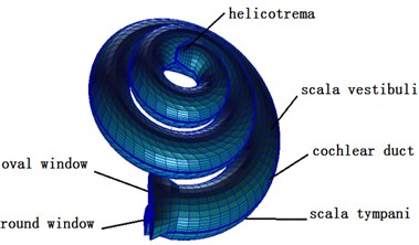
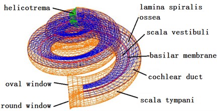
This paper established a three-dimensional spiral cochlear model through PATRAN software, divided meshes for it and set boundary conditions and material parameters. The spiral inner ear had 2.5 cycles. The space in inner ear was divided by vestibular membrane and basilar membrane into three cavities, namely Scala vestibule, cochlear duct and Scala tympani which were filled with lymph (see Fig. 3). The ratio of sectional areas of Scala vestibule, cochlear duct and Scala tympani was 5:3:8. The basilar membrane was 34.86 mm. The thickness and width of basilar membrane presented a linear change. The top and bottom of basilar membrane were 7.5 μm and 2.5 μm thick, and the width was 0.1 mm and 0.5 mm. The cochlear model established in this paper failed to consider the function of CORTI organ. Namely, it did not consider the active mechanism of cochlea. The cochlear model was a passive mode. Finally, this paper used NASTRAN software to conduct a dynamic analysis on three-dimensional fluid-solid coupling.
Meshes were divided as follows: Scala tympani: 7878 nodes and 6200 eight-node hexahedral (hex8) elements whose property was defined as fluid. Scala vestibule: 3131 nodes and 1900 eight-node hexahedral (hex8) elements whose property was defined as fluid. 3 Cochlear ducts: 7878 nodes and 6400 eight-node hexahedral (hex8) elements whose property was defined as fluid. Helicotrema: 990 nodes and 725 eight-node hexahedral (hex8) elements whose property was defined as fluid. Oval window (vestibular window): 98 nodes and 83 four-node quadrilateral (Quad4) elements whose property was defined as 2D-Membrane. Round window (fenestra cochleae): 78 nodes and 62 four-node quadrilateral (Quad4) elements whose property was defined as 2D-Membrane. Basilar membrane: 303 nodes and 400 four-node quadrilateral (Quad4) elements whose property was defined as 2D-Membrane. Osseous spiral lamina: 808 nodes and 600 four-node quadrilateral (Quad4) elements whose property was defined as 2D-Membrane. Vestibular membrane: 1111 nodes and 1000 four-node quadrilateral (Quad4) elements whose property was defined as 2D-Membrane. Shell: 4670 nodes and 4240 four-node quadrilateral (Quad4) elements whose property was defined as 2D-Membrane. All structural meshes of the cochlea were shown in Fig. 3.
Fig. 1Finite element model of the inner ear
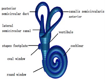
Fig. 2The finite element model of the spiral basilar membrane
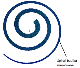
Fig. 3Finite element model of the cochlea
2.2. Governing equations of coupling effects
In this paper, NASTRAN software was used to realize the fluid-solid coupling of 3D human ears, and the corresponding control equation was as follows:
wherein, was mass matrix of solid, was node mass matrix of fluid-solid coupling, was mass matrix of fluid, was structural damping matrix, was damping matrix of fluid, was stiffness matrix of structural solid, was stiffness matrix of fluid, was stiffness matrix of fluid-solid coupling, was transition matrix of the fluid-solid coupling interface, was the displacement matrix, was pressure matrix.
In the fluid-solid coupling model of human ears, the air in the external auditory canal, the air in the middle ear cavity and the lymph fluid in the inner ear were fluid. External ear canal, middle ear auditory bone, cochlear oval window, round window, basilar membrane, bone spiral plate and shell were solid. The interface between air and tympanic membrane, the interface between the air in the middle ear cavity and auditory bones, and the interface between lymphatic fluid in the cochlea, the oval window and the basilar membrane in the round window are fluid-solid coupling interfaces. In the fluid-solid coupling interface, the node of solid elements was mapped to the node of fluid elements. As a result, in the interface, the node velocity and pressure of the solid were consistent with the node velocity and pressure of the fluid. The coupling item was introduced into mass and stiffness matrix of governing equations. By using NASTRAN software, the governing equations are solved by directly strong coupling method, and the bidirectional coupling process can be realized to ensure the computational accuracy of coupling.
2.3. Material property
The structural material property of the cochlear model contained oval window, round window, basilar membrane, vestibular membrane, osseous spiral lamina and shell’s density and elastic modulus, as shown in Table 1. The material of spiral lamina, oval window, round window and vestibular membrane were all based on the linear elastic constitutive model. The parameters which describe the material constitutive model were elastic modulus and Poisson ratio. The elastic modulus of basilar membrane changed among the length direction of basilar membrane. In this research, the elastic modulus of basilar membrane linearly reduced from 50 MPa at the bottom to 3 MPa at the top. The property of lymph was shown in Table 2. The material parameter of the cochlear model was determined based on the previous experimental measurements and numerical models [13-14].
Table 1Structural material parameters of the cochlear model
Elastic modulus (MPa) | Density (t/mm3) | Thickness (mm) | |
Spiral lamina | 141 | 2.2E-009 | 0.1 |
Oval window | 40 | 1.2E-009 | 0.1 |
Round window | 0.2 | 1.2E-009 | 0.01 |
Vestibular membrane | 15 | 1.2E-009 | 0.005 |
Shell | 1.5 | 1.2E-009 | 0.05 |
Vestibular membrane | 1.5 | 1.2E-009 | 0.1 |
Table 2Property of lymph in the cochlear model
Velocity (m·s-1) | Damping | Density (t/mm3) | |
Lymph | 1400 | 0.0007 | 1.0 E-009 |
2.4. Boundary conditions
(1) Applied 80 dB (0.2 Pa) in oval window and simulated the sound pressure excitation of pure sound (100 Hz-10000 Hz);
(2) The outer edge of round window was considered as a fixed constraint;
(3) The displacement of the outer edge of oval window was restricted in direction;
(4) Basilar membrane and vestibular membrane were the interface of fluid-solid coupling.
3. Computational results and analysis
3.1. A comparison with the experimental data
When the external excitation was 80 dB, this model performed simulation and obtained the relationship of ratio of basilar membrane amplitude to stapes amplitude (the central point of oval window) with frequency at the position of 12 mm from the top to the bottom of basilar membrane and drew it in Fig. 4. At the same time, Fig. 4 has presented the experimental data of Gundersen [25] and Stenfelt [26] and finite element simulation of Kim [27]. Fig. 5 reflected the comparison between simulation phase data and experimental data. From the curve of Fig. 4, the optimal frequency in the experiments of Gundersen was 3500 Hz, similar to the finite element result of Kim. The optimal frequency in this paper was 2500 Hz, which was similar to the experimental result of Setenfelt. Therefore, the simulation result in this paper was well consistent with the experimental result. In addition, the contour for the pressure of Scala vestibule and the displacement of basilar membrane obtained based on the model simulation of this paper were shown in Fig. 6 which also reflected the distribution of pressure and the vibration characteristics of basilar membrane in the cochlea.
Fig. 4Ratio of basilar membrane amplitude to stapes amplitude with frequency
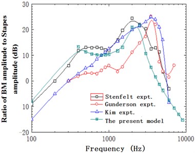
Fig. 5Ratio of basilar membrane phase to stapes phase with frequency
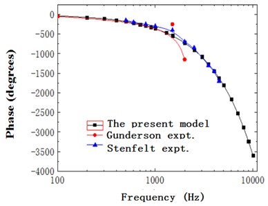
Fig. 6a) Contour of pressure distribution in the cochlea; b) contour of basilar membrane amplitude
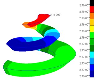
a)
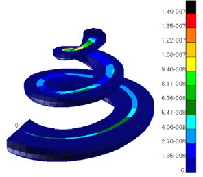
b)
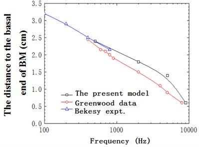
Fig. 7 defined the position of response peak of basilar membrane at various frequencies in the longitudinal direction of the cochlea. The black solid line represented the result in this paper, the red solid line was the result in Greenwood [28], and the blue solid line was the result in Békésy [20] through experimental measurement. Through conducting a comparative analysis, this paper found that the result of this model was quite close to that of experiments. Meantime, it could be seen that the peak values were corresponding to different positions longitudinally in the basilar membrane for different frequencies, which reflected the frequency selectivity of basilar membrane.
Fig. 7The distance to the basal end of BM with frequency
3.2. Characteristics of the spiral basilar membrane
Previous scholars simulated the motion characteristics of simplified cochlear models through finite element software. In simplified models, basilar membrane was a straight simplified model. Therefore, the change of horizontal motion at the same position of basilar membrane was consistent, which found it impossible to analyze the horizontal motion characteristics of basilar membrane and neglected the impact of curvature on its motion in the actual cochlea. As a result, this paper analyzed and studied the impact of curvature on spiral basilar membrane through establishing the model.
To study the change of basilar membrane along curvature, the point with the minimum radius at any cross section was set as point 1 referring to inner radius and the point with the maximum radius was set as point 5 referring to outer radius, as shown in Fig. 8. When the model was excited, the change trend of ratio of inner radius amplitude to outer radius amplitude in the longitudinal direction of basilar membrane was drawn in Fig. 9. Fig. 8 presented the distribution rule of ratio of inner radius amplitude to outer radius amplitude in the longitudinal direction of basilar membrane at 6 frequencies from 1 to 6 kHz. Meanwhile, it could be clearly observed that curves in the figure intersected at 22 mm. As shown from Fig. 8, the ratio of inner radius amplitude to outer radius amplitude gradually increased in the longitudinal direction of basilar membrane in the intermediate frequency region and the ratio of outer radius amplitude to inner radius amplitude gradually decreased in the ring direction of the basilar membrane in the high frequency region. It was caused by resonance of basilar membrane in the top of cochlea in the low frequency and at the base of cochlea in the high frequency. The ratio of outer radius amplitude to inner radius amplitude would be increased in the case of resonance.
There is an intersection at 22 mm in Fig. 9, and the cross section at this position could be selected for research. Meantime, the cross section at 12 mm could be then chosen for analysis as the result was consistent with corresponding experimental data. The horizontal amplitudes of basilar membrane at 12 mm and 22 mm from the top to the bottom of basilar membrane at different frequencies were computed and the impact of curvature on spiral basilar membrane was considered.
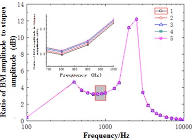
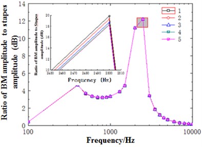
Fig. 10 showed the ratio of basilar membrane amplitude to stapes amplitude with frequency at 12 mm. As shown from Fig. 10(a), the change trends of ratio of basilar membrane amplitude to stapes amplitude at different positions of cross section with frequency were roughly the same and the maximum values were obtained at the frequency of about 2500 Hz. It could be seen from the enlarged drawing of Fig. 10(a) that the amplitude of basilar membrane increased with the decrease of curvature. However, Fig. 10(b) showed that amplitudes at different positions of cross section changed with frequency and increased with the decrease of curvature.
Fig. 8Partial enlargement of spiral basilar membrane
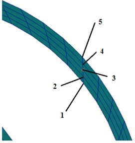
Fig. 9Ratio of outer radius amplitude to inner radius amplitude
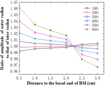
Fig. 10a) Ratio of basilar membrane amplitude to stapes amplitude at the position of 12 mm in the low frequency; b) ratio of basilar membrane amplitude to stapes amplitude at the position of 12 mm in the high frequency
a)
b)
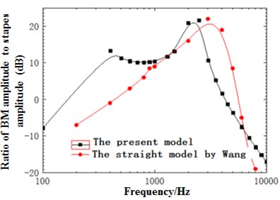
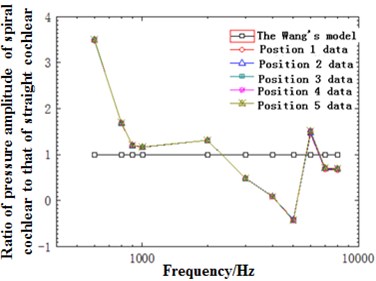
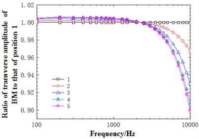
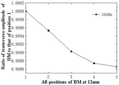
Fig. 11(a) presented the diagram of comparison between the sound pressure value of the model and straight-cavity model established by Wang [29] at 12 mm in the basilar membrane. As shown from the figure, the overall trends of the model and Wang were similar, gradually increased before the characteristic frequency and quickly decreased after reaching the characteristic frequency. However, the peak value of the model moved forward compared with the straight-cavity model of Wang and obtained the characteristic frequency around 2500 Hz. The data of straight-cavity model established by Wang was taken as the standard and the ratio of sound pressure value in different curvature radiuses to different curvature radiuses with frequency at the cross section of the model at 12 mm was drawn in Fig. 11(b). It could be noticed from the figure that the sound pressure value of the model was generally higher than that of straight-cavity model in the low and middle frequency. In the meantime, the horizontal sound pressures of spiral basilar membrane showed some small differences with frequency. To better reflect the horizontal change of basilar membrane amplitude with frequency, the ratio of amplitude of various points to point 1 at the cross section was selected to reflect the degree of deviation with frequency and drawn in Fig. 11(c). It could be seen from the figure that the deviation trends of various points were the same with the decrease of curvature. However, the gradual increase of deviation degree indicated that amplitude gradually increased with the decrease of curvature. Deviation was relatively smaller at low frequencies, and there was a sudden change around 2500 Hz and similar to the optimal frequency at this position. Thus, it could be seen that the optimal frequency was a turning point of horizontal displacement of basilar membrane. After the turning point, deviation degree increased at the high frequency region, which indicated that amplitude gradually decreased with the decline of curvature. Thus, curvature had an influence on basilar membrane amplitude at different frequencies, which could not be reflected by previous straight-cavity models.
Fig. 11(d) showed the ratio of displacement amplitude of various points at 12 mm to amplitude of point 1 at the optimal frequency, namely 2500 Hz. As shown in the figure, basilar membrane amplitude decreased with the decline of basilar membrane curvature under the action of 2500 Hz. Meanwhile, the decrease trend gradually tended to be stable.
Fig. 11a) Ratio of basilar membrane amplitude to stapes amplitude at 12 mm; b) ratio of sound pressure of spiral basilar membrane to sound pressure of straight-cavity basilar membrane at 12 mm; c) ratio of horizontal basilar membrane amplitude at 12 mm to amplitude of point 1; d) ratio of displacement amplitude of various points at 12 mm to amplitude of point 1
a)
b)
c)
d)
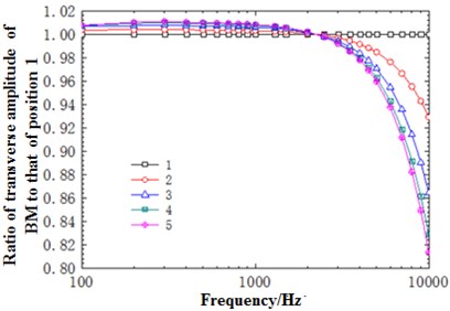
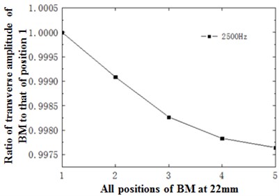
Fig. 12(a) described the change trend of horizontal amplitude of the cross section at 22 mm with different frequencies. From the perspective of trend, this change trend was similar to that of the cross section at the position of 12 mm with frequency. Similarly, an intersection appeared at the frequency of around 2500 Hz. The horizontal amplitude of frequency at the point of intersection was drawn in Fig. 12(b). As shown in the figure, the amplitude decreased nonlinearly with the decrease of curvature, and was similar to that of the cross section at 12 mm. Compared with the cross section at 12 mm, however, the deviation degree of amplitude with frequency and the decrease degree at the same frequency and different positions were relatively larger at the cross section at 22 mm.
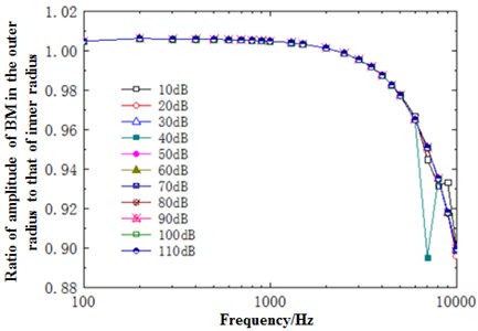
Fig. 13 showed the relationship between the ratio of outer radius to inner radius of basilar membrane at the position of 12 mm and sound pressure. In the figure, different curves stood for the change of ratio of outer radius amplitude to inner radius amplitude with frequency when the excitation was changed from 10 dB to 110 dB. As shown from the figure, the change of ratio of outer radius amplitude to inner radius amplitude was small and tended to be stable with the increase of frequency before 2500 Hz. The change trend was dramatic with the increase of frequency after 2500 Hz. Thus, it could be seen that high frequencies had a great influence on the displacement of basilar membrane at different curvatures. In the meanwhile, the figure showed that the change trend of ratio of outer radius amplitude to inner radius amplitude generally remained unchanged with the increase of sound pressure and only deviated apparently in the case of 40 dB and high frequencies.
Fig. 12a) Ratio of horizontal basilar membrane amplitude at 22 mm to amplitude of point 1; b) ratio of displacement amplitude of various points at 22 mm to amplitude of point 1
a)
b)
Fig. 13Ratio of outer radius amplitude to inner radius amplitude with sound pressure and frequency at 12 mm
3.3. Amplification of basilar membrane
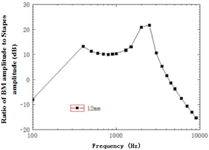
Fig. 14 described the increase trend of sound intensity with frequency in the basilar member at 12 mm when the excitation was 80 dB. As shown in the figure, sound intensity increased linearly with the increase of frequency at low frequencies, reached a peak around 400 Hz, increased by 13 dB, rose after a temporary decrease trend, reached a maximum about 2500 Hz, generally rose by 21 dB and gradually decreased, which indicated that basilar membrane played a role in amplifying sound intensity and the amplified maximum and minimum appeared in the characteristic frequencies of corresponding positions. At the same time, the mode was spiral. Compared with spiral basilar membrane, the change of amplitude at every cross section differed with curvature. Fig. 9 just reflected the change of ratio of inner radius amplitude to outer radius amplitude of basilar membrane with curvature at different cross sections. The amplitude at the outer radius was about 1.06 times that at the inner radius at most and 0.96 times at least. Therefore, the differences of amplitude at the outer and inner radiuses changed with frequency, expanded the sound perception range of cross sections and embodied the amplification of spiral basilar membrane to sound.
Fig. 14Ratio of basilar membrane amplitude to stapes amplitude at 12 mm
3.4. Argumentation for the existence of travelling wave
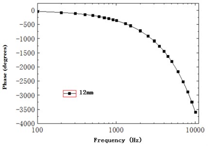
As shown in Fig. 15, the phase difference of basilar membrane at 12 mm gradually accumulated with the increase of frequency and showed an obvious hysteresis phenomenon. Besides, the slope of phase gradually declined with frequency, changed slowly before 2500 Hz and dramatically after 2500 Hz, kept consistency with the phenomenon of substantial phase accumulation and delay described by the characteristics of travelling wave, and supported the theory of existence of travelling wave.
Fig. 15Phase of basilar membrane at 12 mm
4. Conclusions
This paper established a spiral cochlear model according with actual human ears, improved previously straight cochlear model and verified the correctness of model in this paper through the consistency between the computational result and experimental data.
When the excitation was 80 dB, the change trend of amplitude in the longitudinal direction of basilar membrane was reflected by the curve change of ratio of outer radius amplitude to inner radius amplitude. Curves intersected at 22 mm. The ratio increased with the frequency before the intersection and the situation was the opposite after the intersection. In the meanwhile, the maximum position in the basilar membrane also changed with the frequency, which reflected the frequency selectivity of basilar membrane in the longitudinal direction.
Through an analysis, the displacement amplitude of basilar membrane at the horizontal cross section changed little in the low frequency and dramatically in the high frequency. And there is a turning point at the optimal frequency 2500 Hz. Thus, it could be seen that curvature had great influence on the displacement of basilar membrane when the stimulation frequency was relatively higher. The change rule could not be presented in straight-cavity models. At the same frequency of 2500 Hz, the amplitude of basilar membrane decreased with the decrease of basilar membrane curvature. In the meanwhile, the decrease trend tended to be stable gradually. Thus, adopting a three-dimensional spiral cochlear model could better express its actual change at high frequencies and reflect the motion characteristics of basilar membrane.
Meantime, spiral basilar membrane expanded the sound perception range of basilar membrane due to its spiral-shaped structure and amplified sound intensity. The amplified maximum and minimum appeared in corresponding characteristic frequencies.
Regarding the controversial issue of existence of travelling wave in cochlear research, the phase data simulated by this paper presented a lot of phase accumulation and delay, verified and supported the idea of Békésy about the existence of travelling wave. The work of this paper provided a real and accurate platform of numerical computation for the simulation analysis of human cochlea.
References
-
Sotomayor M., Weihofen W. A., Gaudet R., et al. Structure of a force-conveying cadherin bond essential for inner-ear mechanotransduction. Nature, Vol. 492, 2012, p. 128-132.
-
Oliver D., He D. Z. Z., Klocker N., et al. Intracellular anions as the voltage sensor of Prestin, the outer hair cell motor protein. Science, 2001, p. 2340-2343.
-
Verpy E., Weil D., Leibovici M., et al. Stereocilin-deficient mice reveal the origin of cochlear waveform distortions. Nature, Vol. 456, 2008, p. 255-259.
-
Colantonio J. R., et al. The dynein regulatory complex is required for ciliary motility and otolith biogenesis in the inner ear. Nature, Vol. 457, 2009, p. 205-209.
-
Maoiléidigh D. O., Hudspeth A. J. Effects of cochlear loading on the motility of active outer hair cells. PNAS, Vol. 110, Issue 14, 2013, p. 5474-5479.
-
Antoine M. W., Hübner C. A., Arezzo J. C. A causative link between inner ear defects and long-term striatal dysfunction. Science, 2013, p. 1120-1123.
-
Sage C., Huang M., Karimi K., et al. Proliferation of functional hair cells in vivo in the absence of the retinoblastoma protein. Science, 2005, p. 1114-1118.
-
Ryugo D. K., Kretzmer E. A., Niparko J. K. Restoration of auditory nerve synapses in cats by cochlear implants. Science, 2005, p. 1490-1492.
-
Chen W., Jongkamonwiwat M., Abbas L., et al. Restoration of auditory evoked responses by human ES-cell-derived oticprogenitors. Nature, Vol. 490, 2012, p. 278-282.
-
Thorne M., Salt A. N., Demott J. E., et al. Cochlear fluid space dimensions for six species derived from reconstructions of three-dimensional magnetic resonance images. The Laryngoscope. Vol. 109, Issue 10, 1999, p. 1661-1668.
-
Givelberg Edward, Bunn Julian A comprehensive three-dimensional model of the cochlea. Journal of Computational Physics, Vol. 191, 2003, p. 377-391.
-
Yoon Y. J., Steele C. R., Puria S. Feed-forward and feed-backward amplification model from cochlear cytoarchitecture: an interspecies comparison. Biophysical Journal, Vol. 100, 2011, p. 1-10.
-
Gan R. Z., Reeves B. P., Wang X. L. Modeling of sound transmission from ear canal to cochlea. Annals of Biomedical Engineering, Vol. 35, 2007, p. 2180-2195.
-
Zhang Xiangming, Gan R. Z. A comprehensive model of human ear for analysis of implantable hearing devices. IEEE Transactions on Biomedical Engineering, Vol. 58, Issue 10, 2011, p. 3024-3027.
-
Koehler K. R., Mikosz A. M., Molosh A. I., et al. Generation of inner ear sensory epithelia from pluripotent stem cells in 3D culture. Nature, Vol. 500, 2013, p. 217-221.
-
Tanimoto M., Ota Y., Inoue M., et al. Origin of inner ear hair cells: morphological and functional differentiation from ciliary cells into hair cells in zebrafish inner ear. The Journal of Neuroscience, Vol. 31, Issue 10, 2011, p. 3784-3794.
-
Bohnke F., Arnold W. 3D-finite element model of the human cochlea including fluid-structure couplings. ORL, Vol. 61, 1999, p. 305-310.
-
Lim K. M., Steele C. R. A three-dimensional nonlinear active cochlear model analyzed by the WKB-numeric method. Hearing Research, Vol. 170, 2002, p. 190-205.
-
Andoh M., Wada H. Prediction of the characteristics of two types of pressure waves in the cochlea: theoretical considerations. Journal of the Acoustical Society of America, Vol. 116, 2004, p. 417-425.
-
Von Békésy G. Experiments in Hearing. McGraw-Hill Book Company, New York, 1960.
-
Dancer A., Franke R. Intracochlear sound pressure measurements in guinea pigs. Hearing Research, Vol. 2, 1980, p. 191-206.
-
Magnan P., Avan P., Dancer A., Smurzynski J., Probst R. Reverse middle-ear transfer function in the guinea pig measured with cubic difference tones. Hearing Research, Vol. 107, 1997, p. 41-45.
-
Dancer A. Experimental look at cochlear mechanics. Audiology, Vol. 31, 1992, p. 301-312.
-
Magnan P., Dancer A. Intracochlear acoustic pressure measurements: transfer functions of the middle ear and cochlear mechanics. Audiology and Neuro-Otology, Vol. 4, 1999, p. 123-128.
-
Gundersen T., Skarstein O., Sikkeland T. A study of the vibration of the basilar membrane in human temporal bone preparations by the use of the Mossbauer effect. Acta Otorrinolaringologica, Vol. 86, 1978, p. 225-232.
-
Stenfelt S., Puria S., Hato N., Goode R. L. Basilar membrane and osseous spiral lamina motion in human cadavers with air and bone conduction stimuli. Hearing Research, Vol. 181, 2003, p. 131-143.
-
Kim N., Homma K., Puria S. Inertial bone conduction: symmetric and anti-symmetric components. Association for Research in Otolaryngology, Vol. 12, 2011, p. 261-279.
-
Greenwood D. D. A cochlear frequency-position function for several species-29 years later. The Journal of the Acoustical Society of America, Vol. 87, 1990, p. 2592-2605.
-
Wang X. L. FE simulation of sound transmission in human ear with an active cochlea model. Journal of Vibration and Shock, Vol. 31, Issue 21, 2012, p. 41-45.
Cited by
About this article
This project is supported by Fundamental Research Funds for the Central Universities; Research innovation project of Shanghai Municipal Education Commission; Science and Technology Guidance Project of Chinese Textile Industry Association.
This paper was written and completed by the first author; numerical simulation was conducted by the second author; translation was completed by the third and fourth author; the final check and submission were finished by the other authors.
