Abstract
In order to study the dynamic characteristics of a rotor system incorporated with roller bearings, a detailed finite element model of the rotor system was established. Both the roller bearings and pedestals were considered. Then investigations on dynamic characteristics of the rotor system were conducted, in which critical speeds and unbalance response of the rotor system were obtained and analyzed. Following conclusions can be reached from the numerical results: 1) the second and third critical speeds of the rotor system are 25260 rpm and 113400 rpm, both of which are outside of the operating speed range 31800 rpm-55320 rpm. 2) Within the operating speed range 31800 rpm-55320 rpm, unbalance response of both the centrifugal impeller and the turbine disk are smaller than the corresponding clearances. However, with increasing rotational speed, amplitude of the unbalance response for the centrifugal impeller increases while that of the turbine disk decreases.
1. Introduction
The rotor system is the main source of vibration for the aero-engine. Recently, many scholars have studied the dynamic characteristics of rotor system with the finite element method. Huang Xinzhong et al. [1] applied the finite element method to obtain the dynamic characteristics of a compressor rotor system. Sun Qiang et al. [2] studied the natural frequencies of the blades for a low-pressure compressor by combining the finite element method and the nonlinear contact theory. In reference [3], DENG Sier et al adopted the finite element method to investigate the dynamic behavior of a dual-rotor system. In the study, influences of rotational speed, number of rollers in intermediate bearing and bearing parameters on the dynamic behavior of the dual-rotor system were studied. The numerical results were validated with the experimental results, which verify the correctness of the finite element method.
In current work, dynamic characteristics of a rotor system incorporated with roller bearing and squeeze film damper are investigated. In the first part of this work, stiffness and damping of the supports are analyzed in detail. Then, with previously obtained stiffness and damping, the finite element method is adopted to investigate the dynamic characteristics of the rotor system.
2. Modeling of the rotor system
The 3-D model of rotor system is shown in Fig. 1. In general, the whole rotor system consists of centrifugal impeller, gas turbine and shaft. Support 1 is constituted by an angular contact ball bearing and a bearing pedestal. Support 2 consists of a cylindrical roller bearing and a squirrel cage.
2.1. Bearing
The bearing parameters are listed in Table 1.
Bearing stiffness can be expressed with Eq. (1) and Eq. (2) [4].
For angular contact ball bearing:
where represents the roller diameter (mm), denotes the roller number, represents the contact angle, represents the radial load (N).
Fig. 13-D model of the rotor system
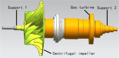
Table 1Parameters of the bearings in different locations
Bearing location | Bearing type | Roller number | Roller diameter (mm) | Outer ring diameter (mm) | Inner ring diameter (mm) | Width of outer ring (mm) | Width of inner ring (mm) |
Support 1 | Angular contact ball bearing | 14 | 7.1438 | 52 | 30 | 11 | 11 |
Support 2 | cylindrical roller bearing | 14 | 6 | 61.8 | 28 | 13 | 63 |
For cylindrical roller bearing:
where represents the effective length of roller (mm), represents the number of rollers, represents the contact angle, represents the radial load (N).
It can be seen from Eq. (1) and Eq. (2) that the radial external load has great influence on the stiffness of the bearing. Thus, the external loads exerted by the rotor system must be analyzed to obtain the stiffness of the bearings. Weight distribution of the rotor system is shown in Fig. 2. The weight of the centrifugal impeller is 27.59 N. The weight of the gas turbine rotor assembly is 27.43 N, and the weights of other components are 24.42 N, 5.25 N and 5.03 N, respectively. Based on the principal of force equilibrium and the principal of moment equilibrium, the radial load of the bearing in support 1 is 37.11 N, and the radial load of the bearing in support 2 is 49.41 N.
Based on Eq. (1) and Eq. (2), the stiffness of the bearings for support 1 and support 2 are listed in Table 2.
Fig. 2Rotor system bearing loads distribution
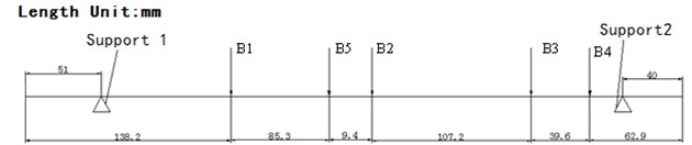
Table 2Stiffness of the bearings in different locations
Bearing location | Bearing type | Radial load (N) | Bearing stiffness (107N/m) |
Support 1 | Angular contact ball bearing | 37.11 | 4.71 |
Support 2 | cylindrical roller bearing | 49.41 | 53.86 |
2.2. Bearing pedestal
2.2.1. Bearing pedestal of support 1
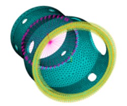
The finite element model of the pedestal is shown in Fig. 3. In this model, all DOFs of the nodes on the flange are constrained. A central node and a rigid region are created at the axial location of the bearing. A unit force is imposed on the central node and the displacement is obtained. The displacement of the central node is 1.6663×10⁻⁹m, and the stiffness of the bearing pedestal is:
Fig. 3The finite element model of the bearing pedestal in support 1
2.2.2. Squirrel cage in support 2
The geometry dimensions of the squirrel cage are listed in Table 3. The stiffness of the squirrel cage can be expressed as [5]:
where is the number of ribs, is elastic modulus, is the length of the ribs, is the width of rib cross section, is the height of rib cross section.
The elastic modulus of the material is 210 GPa. Based on Table 3 and Eq. (4), the stiffness of the squirrel cage is 9.3×10⁶N/m.
Table 3Parameters of the squirrel cage
Elastic modulus (GPa) | Number of ribs | Length of ribs (mm) | Width of rib cross section (mm) | Height of rib’s cross section (mm) |
210 | 10 | 35 | 4 | 4 |
2.3. Support
In this paper, the stiffness of the support should be considered as a combination of two springs in series. Thus, the support stiffness is:
where is support stiffness, is bearing stiffness and is bearing pedestal stiffness.
According to the results of Section 2.1 and Section 2.2, the support stiffness calculated with Eq. (5) is shown in Table 4.
Table 4Stiffness of the supports
Location | Bearing stiffness (107N/m) | Bearing pedestal stiffness (107N/m) | Support stiffness (107N/m) |
Support 1 | 4.71 | 2.03 | 1.42 |
Support 2 | 53.86 | 1.25 | 1.22 |
2.4. Squeeze film damper
The parameters of squeeze film damper are listed in Table 2.5. The squeeze film damper is considered as a liner damper and the equivalent damping is [6]:
where represents the dynamic viscosity of the oil film, represents the width of film, represents the radius of the oil film ring, represents the radius of the oil film clearance, and represents eccentricity.
According to Table 5, the damping of the squeeze film damper is 195.89 N·s/m.
Table 5Parameters of the squeeze film damper
Dynamic viscosity (Pa·s) | Length (mm) | Radius (mm) | Clearance (mm) | Eccentricity ratio |
5.02×10⁻³ | 9.3 | 30.9 | 0.1 | 0.0184 |
2.5. The roller bearing rotor system
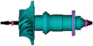
With the previously obtained support stiffness and damping, the finite element model of the roller-bearing rotor system is established, which is shown in Fig. 4. To simplify the modeling process and reduce the computational effort, blades of the turbine are modeled with one MASS21 element [7]. The supports are modeled with COMBI214 element. For the rest parts of the rotor system, the SOLID95 element is adopted. In total, the whole model is divided into 178417 elements and 72220 nodes.
Fig. 4The FE model of roller-bearing rotor system
3. Dynamic characteristics of the rotor system
3.1. Critical speed
Based on the FE model established in Section 2.5, critical speeds of the rotor system are obtained. The operating speed range of the rotor system is 31800 r/min-55320 r/min. And the rotational speed range 0-126000 r/min, which covers the operating speed range, is applied to the finite element model. The Campbell diagram is shown in Fig. 5. The first three critical speeds are listed in Table 6.
From Table 6 it can be seen that the distinction between first forward procession and backward procession is not so clear. The second critical speed is 20.6 % lower than the lower margin of the speed range (31800 r/min). The third critical speed is 105 % higher than the largest operating speed (55320 r/min). From the theory in reference [8], it is quite obvious that there is an enough safety margin between the critical speeds and the operating speed range. Also, there is no critical speed in the operating speed range, which ensures the safe and smooth operation of the rotor system.
Fig. 5Campbell diagram of rotor system
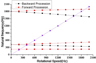
Table 6The first three critical speeds
Order | Critical speed frequency (Hz) | Critical speed (r/min) |
First | 228 | 13680 |
Second | 421 | 25260 |
Third | 1890 | 113400 |
3.2. Unbalance response
Although the critical speeds of the rotor system have enough safety margins, the unbalance response of the rotor system in operating speed range needs to be considered for avoiding rubbing between the rotor and the case.
The residual imbalance of the rotor system is about 0.5 g·cm and is distributed at the front and rear end of the rotor system. In the operating speed range 31800 r/min-55320 r/min, the unbalance response of the rotor system is obtained with previously established FE model.
In the actual engine, the rubbing is prone to the turbine disk and the centrifugal impeller. Therefore, the radial displacements of the turbine disk and the centrifugal impeller under different rotational speeds are shown in Fig. 6.
Fig. 6Unbalance responses of turbine disk and centrifugal impeller
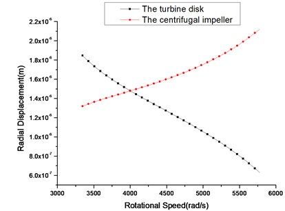
In Fig. 6, the amplitudes of the turbine disk and the centrifugal impeller have opposite trends. The clearance between the turbine and the case is 9×10⁻⁴m and the clearance between the centrifugal impeller and the case is 7×10⁻⁴m. It can be seen from Fig. 6 that the maximum amplitudes of the turbine disk and the centrifugal impeller are about 1.9×10⁻⁶m and 2.1×10⁻⁶m, respectively. Therefore, the rotor system can operate safely and smoothly in the operating speed range.
4. Conclusions
In this paper, the critical speed and the unbalance response of the roller bearing rotor system are analyzed, which provides a theoretical reference for the optimization of the rotor system. The conclusions are drawn as follows: 1) the second and third critical speeds of the rotor system are 25260 rpm and 113400 rpm, which are 20.6 % lower than the lower margin of the speed range and 105 % higher than the largest operating speed, respectively, which means there is enough safety margin between the critical speeds and the operating speed range. 2) Within the operating speed range 31800 rpm-55320 rpm, unbalance response of both the centrifugal impeller and the turbine disk are smaller than the corresponding clearances, which means that the rotor system can operate safely in the operating speed range.
References
-
Huang Xinzhong, Zhao Junsheng Finite element simulation on vibrating characteristics of compressor based on ANSYS. Machinery Design and Manufacture, Vol. 2, 2012, p. 12-13, (in Chinese).
-
Sun Qiang, Zhang Zhongping, Li Chunwang, Qiao Yanjiang, Zhao Wenzhen Finite element investigation of an aero-engine pin type blade’s natural frequency. Journal of Applied Mechanics, Vol. 23, Issue 9, 2006, p. 420-472, (in Chinese).
-
Deng Sier, He Fengxiang, Yhang Haisheng, Li Yunlong Dynamic characteristics analysis of a dual rotor rolling bearing coupling system in an aero engine. Journal of Aerospace Power, Vol. 25, Issue 10, 2010, p. 2387-2395, (in Chinese).
-
Fu Gaocai Aero Engine Design Manual. Aviation Industry Press, 2007.
-
Tang Rui, Guo Jian, Luo Zhong, Wang Deyou, Liu Yongquan Optimization design by steps method for the structural parameters of the squirrel cage type elastic support. Aeroengine, Vol. 42, Issue 4, 2016, p. 38-43, (in Chinese).
-
Cheng Li, Li Shuaiying, Qian Zhengwen The vibration characteristics of bistable disk rod fastening rotor system with squeeze film damper. Journal of Aerospace Power, Vol. 28, Issue 9, 2013, p. 2044-2049, (in Chinese).
-
Xiao Qilin, Wang Keming, Li Quancheng Blade simplification for the finite element investigation of rotor system critical speed. Journal of Shenyang Institute of Aeronautical Engineering, Vol. 30, Issue 12, 2013, p. 11-15, (in Chinese).
-
Zhang Dayi, Liu Yehui, Hong Jie, Ma Yanhong The establishment and analysis of the whole engine dynamics model vibration characteristics. Journal of Propulsion Technology, Vol. 36, Issue 5, 2015, p. 765-773, (in Chinese).
About this article

