Abstract
A digital image hiding scheme based on the breakup of spiral waves is presented in this paper. This scheme does not require initial conditions perturbation and embedding of the secret image is done during the evolution of a self-organizing pattern. Such features increase the security, but still enable an effective decoding of the secret image. The concept of the order of a 2D linear recurrent sequences are used to estimate the complexity of the pattern and select the optimal timing required for the pattern to complete. Computational experiments are used to demonstrate the properties and efficiency of the proposed scheme.
1. Introduction
It is well known that self-organizing patterns can be used for hiding and communicating secret visual images. A secure steganographic communication algorithm is developed in [1-5] where patterns are evolved using reaction-diffusion equations, interactions between competing individuals, patterns produced by the atrial fibrillation model or by an array of non-diffusively coupled nonlinear maps. Listed digital image hiding schemes based on self-organizing patterns use some sort of perturbation of initial conditions. The secret image is represented in the form of a dot-skeleton representation or pixels are inverted in regions corresponding to the secret image. The main objective of this paper is to develop digital image hiding scheme based on self-organizing patterns that would neither use random initial conditions, nor require any perturbations of the initial conditions.
This paper is organized as follows. The physical model governing the formation of patterns is presented in Section 2; the adaptive perturbation strategy is presented in Section 3; the pattern complexity estimation and optimal modeling time selection of an evolving pattern is presented in Section 4; the image hiding scheme is demonstrated in Section 5 and concluding remarks are given in the final section.
2. The spiral wave model based pattern formation
Patterns formation is based on Barkley model [6, 7] which simulates spiral waves in excitable and oscillatory media. The considered model comprises a system of reaction-diffusion equations describing the interaction of the activator and the inhibitor :
where and are local reaction kinetics functions and the parameter is then the ratio of diffusion coefficients. The reaction term in the simplest case [6] is given by:
where the parameter sets the timescale separation between the fast -equation and the slow -equation; and are system parameters. The reaction term is chosen to be nonlinear function, allowing the pattern to evolve into a non-regular spiral wave with breakups [8]:
To simulate this reaction a simple Euler forward scheme is used, where Laplacian is simulated numerically using a finite differences method on a regular square grid with a five-point formula [7]. Such implementation allows to time step reaction terms with relatively little computational efforts.
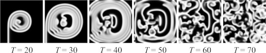
Let us consider a 2D square domain of size with zero-flux boundary conditions. We set the initial conditions as dichotomous patches (vertical for the -field and horizontal for the -field) where the black color corresponds to 0 and the white color – to 1. As discussed in [9], there are sets of parameters , and the spirals may undergo period rotations or various types of meander/break-ups. The evolution of the pattern into a complete brakeage is illustrated in Fig. 1. The time step is set to 0.05; the time-period used for the computation is marked as .
Fig. 1The evolution of a spiral wave with breakups (u-field only) with parameters set to: L=100, a=0.7, b=0.06, dt=0.05ϵ=0.1, g=u3-v
3. Adaptive perturbation strategy
The construction of a digital image hiding scheme based on self-organizing patterns requires the formation of two patterns. The nonlinear model of the system governs the evolution of one pattern from a predetermined set of initial conditions – while the evolution of the second one is started from the perturbed initial conditions [1-5]. The secret image leaks in a form of a difference image between these two patterns:
where and are the grayscale levels of the pixel in the first and the second patterns. The difference image is black if two patterns are identical.
Image hiding scheme constructed based on spiral waves modeled patterns requires a slightly different approach than in [1-5]. Two images are still required, but as it is noted in [10], it is impossible to get a reasonable difference image of two patterns created using spiral wave model if only initial conditions are modified. Propagating waves vanish small perturbations during long simulations required for pattern to form. To avoid this, perturbations can be introduced only at the end of simulation.
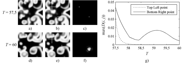
Let us set a computation experiment where the perturbation into the second pattern is introduced at time moment and the evolution of both perturbed and unmodified patterns is terminated at . During this experiment smaller pattern of size is used; other parameters are kept the same. Two pixels of the second pattern are perturbed at by changing its value by 5 % (Fig. 2). It appears that even if perturbations are introduced near the end of simulation the decay of the contrast of the perturbed pixel is not always monotonic and depends on the location of the pixel in respect to the breaking waves (Fig. 2). This effect can be explained by the interaction between the perturbation and the propagating front of the breaking spiral wave. The top left point remains in the calm zone during the whole-time interval of evolution (Fig. 2(b); Fig. 2(e)). On the contrary, the bottom right point is located in the region of the formation of the breakup wave. It appears that the effects caused by the perturbation at the top left point are completely overwhelmed by the effects caused by the perturbation at the bottom right point (Fig. 2(f)). Therefore, the evolution of the pattern in the difference image is sensitive to the geometrical location of the perturbation point in respect to the evolving front of the propagating breakup wave. It is clear that a strategy based on straightforward perturbations of the evolving pattern at a preselected set of points would not be applicable for hiding a secret in the difference image.
Fig. 2The perturbation at the top left point is introduced in the area where no new breakup waves occur during the rest of simulation; thus, the maximum spot intensity decreases monotonically. The bottom right perturbation point is in the area where multiple breakup waves pass, making intensity of the spot to fluctuate in the difference image
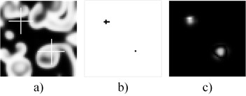
The solution is an adaptive perturbation strategy offered in [10]. Consider the same experiment as in Fig. 2, but change the perturbation of the top left point from a single pixel to 6 pixels (Fig. 3(b)). Note that the intensity of perturbations is kept the same at all points. Now intensity of both points and occupied area in the difference image become of almost identical (Fig. 3(c)). Although, this approach requires experimental or optimization algorithm based adjusting to produce such difference image, but it allows spiral wave model generated patterns to be used in information hiding applications.
Fig. 3The adaptive perturbation strategy helps to equalize both the intensities and shapes of spots in the difference image
4. Pattern complexity estimation
Depending on the domain size spiral wave with breakups model requires relevant number of time steps to form the complete pattern. Short modeling time could lead to lower pattern complexity, as well as embedded data security. On the other hand, if computation time-period is too long the information hiding algorithm becomes time consuming. To visualize the complexity and estimate an optimal computation time-period of the evolving pattern, the order of 2D linear recurrent sequence (2-LRS) could be employed. It was demonstrated that the order of 2-LRS is able to estimate the complexity of self-organizing patterns with respect to each spatial coordinate [11]. For the further discussion we consider the pattern to be a 2-LRS.
Real-world sequences are usually contaminated with noise, and calculation of the finite order of the sequence is not possible, thus pseudo-orders are used to find estimates. A computational framework for the determination of LRS pseudo-orders based on the SVD of the Hankel matrix was presented by [12]. For a 1D sequence the pseudo-order is computed using the SVD by the following algorithm:
1. A Hankel matrix is formed from the sequence , using the first elements.
2. The SVD of gives the ordered singular values:
3. For a chosen , the pseudo-order of the sequence is defined as the number of singular values greater than :
It was proved in [12] that the pseudo-order of a sequence tends to the true order as , however, setting would lead to a great sensitivity to noise in the sequence . Thus, for real-world applications it is recommended to choose and investigate the pseudo-order.
The proposed 1D concept can be indirectly extended to 2-LRS as demonstrated in [11]. Let be a 2-LRS that is homogenous. This means that the differences between the 1D orders of rows (columns) are not large. Then the row (column) pseudo-order of a 2-LRS can be evaluated by using the algorithm provided with the same on each row (column) and considering the mean value of the pseudo-ranks obtained. Thus, the pseudo row (column) rank of a homogenous 2-LRS computed from the first rows (columns) is defined as:
4.1. Optimal time period of pattern formation
Let us employ 2-LRS pseudo orders to estimate the complexity of the self-organizing patterns based on presented spiral waves model. Initial conditions and parameters for the pattern formation are set the same as in Fig. 1, except that the domain size is increased to = 200, and required to define the pseudo order of row (column) is set to 0.5. Pattern evolution and corresponding order is shown in Fig. 4.
A pattern worm-up period continues till = 25, where column order is decreasing because of the vertical initial conditions. After the wave caused by initial conditions propagate away, the order of both row and column starts increasing. Between = 60 and 80 there is a short stable period induced by waves reflection from the boundaries of the pattern, followed by the second increase interval, where the brakeage all over domain starts forming. Since = 120 the formation of pattern is almost complete, but the order is still slowly increasing; and finally, at = 140 the pattern is complete. Latter interactions of the waves, does not increase the complexity of the pattern, thus = 140 is the optimal time-period required to prepare the pattern. Similar pattern complexity with respect to each spatial coordinate guaranties no horizontal or vertical directionality.
Fig. 4The complexity of an evolving pattern in time. Maximum pattern complexity is reached at T = 140
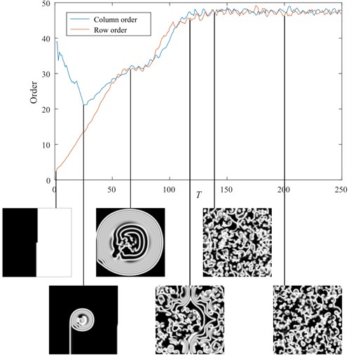
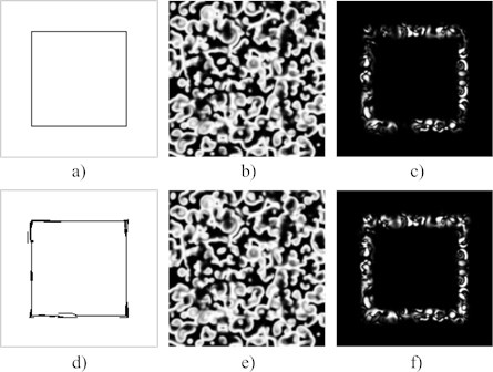
Fig. 5The adaptive perturbation strategy for the formation of a rectangle in the difference image. A thin rectangle-type perturbation (a) is applied to the pattern at T = 140. The resulting pattern at T = 145 is shown in part (b); the difference image (at T = 145) – in part (c). The adaptive perturbation strategy is used to modify the perturbation (d). The resulting pattern (at T = 145) (e); the difference image (f)
5. Hiding a secret in the pattern
The ability to control the shape and the intensity of the deformations in the difference image allows to construct different shapes and geometrical primitives. The 2-LRS based pattern complexity estimation helps finding an optimal pattern computational time-period. To combine these, we continue the computational experiment with the same set of parameters as in Fig. 1 – except that the starting perturbation time is now optimized and perturbations are readjusted using adaptive perturbation strategy. The dimensions of the area used for the pattern formation are set to = 200; the initial perturbation is performed at ; the system continues to evolve until . A rectangle of 1px width border (Fig. 5(a)) is selected as a secret for this experiment. First row of Fig. 5 demonstrates the results when the pattern is directly perturbed at by adding 5 % to its value, and the second row shows results after adaptive perturbation was applied.
It is natural to expect that the produced rectangle in the difference image is discontinuous (Fig. 5(c)) – the formation of the difference image is sensitive to the geometrical locations of the propagating fronts of the breakup waves. To make the geometric object more comprehensible in the difference image the area of perturbation was increased (Fig. 5(d)). It was also noticed that perturbed area is not only sensitive to the area of perturbation, but tends to be moved by a travelling front of the breakup waves. Thus, some perturbations are applied aside from the target employing the travelling front to move it to the required position. Usage of the adaptive perturbation allows to clearly represent a regular geometric shape in the resulting difference image (Fig. 5(f)).
6. Concluding remarks
A digital image hiding scheme based on breaking spiral waves is presented in this paper. It appeared that secret encoding strategies used in previous implementations were unsuitable considering spiral waves. To encode a secret evolving pattern is perturbed – not at the beginning – but in the middle of the pattern formation process. It also appears perturbation is sensitive to the geometrical locations of the travelling fronts of the breakup waves and tends to be moved by the traveling wave front. Therefore, a special adaptive perturbation technique is required for a proper embedding of the secret image into the evolving pattern.
Since the initial perturbations are applied in the middle of the pattern formation the optimal timing for the initial perturbation should be selected. The orders of 2-LRS were used to estimate the complexity of the evolving pattern.
Although, only hiding algorithm is presented in this paper, its primary employment is in secure communication schemes. The presented adaptive perturbation procedure does not impact the decoding of the secret image which remains simple and straightforward.
References
-
Saunoriene L., Ragulskis M. Secure steganographic communication algorithm based on self-organizing patterns. Physical Review E, Vol. 84, 2011, p. 056213.
-
Ishimura K., Komuro K., Schmid A., Asai T., Motomura M. Image steganography based on reaction diffusion models toward hardware implementation. Nonlinear Theory and its Applications, IEICE, Vol. 5, Issue 4, 2014, p. 456-465.
-
Ziaukas P., Ragulskis T., Ragulskis M. Communication scheme based on evolutionary spatial games. Physica A, Vol. 403, 2014, p. 177-188.
-
Vaidelys M., Ragulskiene J., Ziaukas P., Ragulskis M. Image hiding scheme based on the atrial fibrillation model. Applied Sciences, Vol. 5, Issue 4, 2015, p. 1980-1991.
-
Vaidelys M., Ziaukas P., Ragulskis M. Competitively coupled maps for hiding secret visual information. Physica A, Vol. 443, 2016, p. 91-97.
-
Barkley D., Kness M., Tuckerman L. S. Spiral-wave dynamics in a simple model of excitable media: The transition from simple to compound rotation. Physical Review A, Vol. 42, 1990, p. 2489-2492.
-
Dowle M., Mantel R. M., Barkley D. Fast simulations of waves in three-dimensional excitable media. International Journal of Bifurcation and Chaos, Vol. 7, 1997, p. 2529-2546.
-
Bär M., Eiswirth M. Turbulence due to spiral breakup in a continuous excitable medium. Physical Review E, Vol. 48, 1993, p. 1635-1637.
-
Barkley D. Barkley model. Scholarpedia, Vol. 3, 11, p. 2008-1877.
-
Vaidelys M., Lu C., Cheng Y., Ragulskis M. Digital image communication scheme based on the breakup of spiral waves. Physica A: Statistical Mechanics and its Applications, Vol. 467, 2017, p. 1-10.
-
Telksnys T., Navickas Z., Vaidelys M., Ragulskis M. The order of a 2-sequence and the complexity of digital images. Advances in Complex Systems, Vol. 19, 2016, 1650010.
-
Landauskas M., Navickas Z., Vainoras A., Ragulskis M. Weighted moving averaging revisited: an algebraic approach. Computational and Applied Mathematics, 2016, 1-14.
About this article

