Abstract
Time-varying gearmesh stiffness (TVGS) is the main cause of gear vibration, and its accuracy affects the responses of dynamic models. An exponential curve model based on the Saint Venant’s Principle is proposed to calculate the gearmesh stiffness of cracked spur gears in this paper. With the proposed model, the TVGS under the circumstances of healthy condition and four crack cases are computed, whose results have a good agreement with those of finite element method (FEM). Therefore, the exponential curve model can be used to estimate the TVGS and an alternative to FEM in gearmesh stiffness calculation is provided.
1. Introduction
Gearboxes are extensively employed in many industrial applications because of their accurate transmission ratio, high power density and large reduction. However, due to high service loads, harsh operating conditions and fatigue, faults may develop in gears, such as root crack and spalling [1]. Therefore, it is of vital importance to detect initial faults in gear transmission systems for the purpose of condition monitoring [2]. Generally, tooth damage often shows a reduction in gear mesh stiffness and causes the effective capability for bearing load decreasing. Therefore, the severity of tooth damage can be assessed by investigating the reduction of TVGS in gear meshing [3, 4]. In the field of damage mechanism analysis, dynamic modeling of a gear system with simulated faults has been a promising way.
The methods of TVGS calculation in previous studies can generally be categorized as finite element method (FEM) [5], experimental method [6] and analytical method [7-11], among which FEM and experimental method both require precise experiment facilities, though they have a higher accuracy. However, the analytical method provides an alternative to the FEM and the experimental method for its high efficiency to obtain gearmesh stiffness. The potential energy method [7], which belongs to analytical method, is widely adopted in gearmesh stiffness calculation. Tian [8] added the shear stiffness to polish the method, in which the concept of limiting line is proposed when calculating the effective area moment of inertia and effective section area using potential energy method. Liang [9] estimated the gearmesh stiffness of a planetary gear set using a straight limiting line. Chen [10] took non-uniformly distribution of crack along tooth width into consideration. Ma [11] evaluated the gearmesh stiffness of a cracked spur gear set by regarding the limiting line as a parabolic curve.
When a crack occurs and propagates, the effective area moment of inertia and effective section area can be calculated using potential energy method based on a limiting line. The straight line model [9] and parabolic curve model [11] are used to calculate the reduction of bend and shear stiffness in aforementioned works. However, it is obviously inaccurate because the existence of a crack in the beam memorably changes the stress and strain fields in the vicinity of crack, leading to stress concentration at the crack tip. Christides [12] pointed out that according to the Saint Venant’s Principle, the stress concentration at the crack tip decays exponentially with the increasing of distance from the crack location. Carneiro [13] extend this model to Timoshenko beam with shear stiffness considered. Hou [14] summarily reviewed crack beam models and indicated that the exponential curve model coincides best with the practical distribution of stiffness around the crack. Therefore, an exponential curve model for TVGS calculation of crack tooth is proposed in this paper.
In this study, tooth crack is modeled and equations are derived to estimate the gearmesh stiffness of cracked gear set using the potential energy method. Then, a case study is given to illustrate the crack effect on TVGS with an exponential curve model, in which the crack severity levels are modeled with 20 %, 40 %, 60 % and 80 % of the total length of the full through crack, respectively. Finally, the proposed method is compared with FEM to validate its accuracy.
2. Analytical expressions of teeth and gearmesh stiffness
2.1. Fillet-foundation parameter calculation
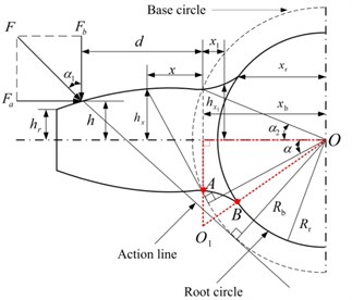
The tooth shape between the base circle and root circle of an involute spur gear is determined by a cutter tip. In order to simulate the realistic tooth profile, the transition curve is assumed as an arc in this paper, as shown in Fig. 1. To calculate the radius of arc , is assumed to be perpendicular to axis, because of the thin tooth thickness. The radius of arc satisfies the following equation:
where is the half of the base tooth angle shown in Fig. 1. Then can be calculated as:
2.2. Gearmesh stiffness calculation by potential energy method
In this paper, the potential energy method is adopted to calculate the TVGS of spur gears [7]. The gearmesh stiffness includes five components: Hertzian contact stiffness , bend stiffness , axial compressive stiffness , shear stiffness and foundation stiffness .Therefore, the total gearmesh stiffness can be expressed as Eq. (3):
where the subscripts 1 and 2 indicate the pinion and gear, respectively; 1 and 2 represent the first and the second pair of meshing teeth, respectively.
The parameters of the gear set are as follows: the tooth number of pinion 20; the tooth number of gear 40; module 1 mm; width of tooth 10 mm; the hub radius of pinion 4 mm; the hub radius of gear 5 mm; Poisson’s ratio 0.3, Young’s modulus 2.068×10¹¹ Pa, pressure angle on pitch circle 20°. And the tooth is modeled as a nonuniform cantilever beam on the root circle, as described in Fig. 1. Then the gearmesh stiffness can be calculated as follows:
where and are the shear modulus and Young’s modulus, respectively; is the tooth width and is Poisson’s ratio; and represent the area moment of inertia and area of the section where the distance from the base circle is , , ; and represent the area moment of inertia and area of the section where the distance from the base circle is , , . The details about , , , , and can be found in Ref. [11]. The TVGS of a healthy spur gear set is shown in Fig. 4.
Fig. 1Cantilever beam model for the spur gear tooth
3. Tooth crack model formulation
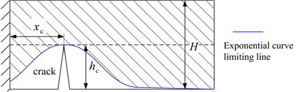
The occurrence of tooth crack reduces the bend stiffness and shear stiffness, while the axial compressive stiffness and Hertzian contact stiffness remain the same [7]. An exponential curve model based on the Saint Venant’s Principle is proposed to describe the variation of the effective area moment of inertia and effective section area . To illustrate the model, a rectangular section beam is selected to explain how the stress decays exponentially in the vicinity of the crack. And the differential equations of the beam can be presented as:
where ; is the area moment of inertia, ; and are the width and height of the beam section; represents the area moment of inertia of the cracked section, ; is the mass of a unit; and is the location and the depth of the crack, as shown in Fig. 2; is an experimental coefficient, and 0.667 [12].
Based on Eq. (9) and Eq. (10), the effective area moment of inertia and section area of a rectangular beam, illustrated in Fig. 2, can be expressed as [12]:
where ; is the area of the undamaged beam, ; is the area moment of inertia of the cracked section, .
Fig. 2Effective loading area of cracked beam
4. TVGS calculation of cracked gears
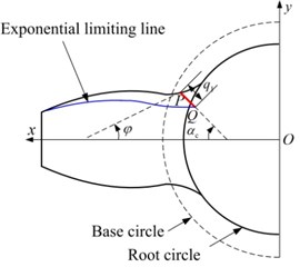
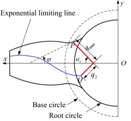
Based on the aforementioned cracked beam model, an exponential curve model is proposed to compute the TVGS of cracked gears. The exponentially decayed curve is shown in Fig. 3, then and can be expressed as follows:
where is the coordinate of crack tip in direction; is the tooth thickness at the location of the crack tip; and can be expressed as , , , respectively; and are the crack lengths when the crack is upon the central line and beyond the central line, respectively; represents the direction of crack propagation, and there is 45°.
The bend stiffness and shear stiffness of the cracked tooth are presented as follows:
The location where crack starts is determined by 30° tangent method, shown as 30° in Fig. 3. Based on the proposed method, four cases with different crack lengths are calculated, and the parameters are listed in Table 1. The TVGS of four cases is given in Fig. 4.
Table 1Parameters of four crack cases
Crack level | 20 % | 40 % | 60 % | 80 % |
Crack length | 0.6 mm, 0 | 1.1 mm, 0 | , 0.3 mm | , 0.8 mm |
5. Comparison with a finite element model
To validate the effectiveness of the TVGS calculated by potential energy method in the proposed model, a 3D finite element model using Solid185 elements with three teeth is adopted. A straight line with an angle of 45° is used to simulate the crack propagation on the pinion tooth, and four crack cases are modeled with the parameters in Table 1. In the finite element model, the load is applied on the hub bore of pinion and the hub bore of gear is fully constrained. Each node of the elements of the pinion is constrained to move only in the direction which is tangential to the hub bore. When the deformation in the direction of action line is acquired from FEM, the gearmesh stiffness can be obtained. Then the stiffness results of healthy condition and four crack cases by FEM are displayed in Fig. 5.
Fig. 3Exponential curve model on cracked tooth: a) q1+q2≤qmax; b) q1+q2>qmax
a)
b)
Fig. 4TVGS of four cases of cracked tooth
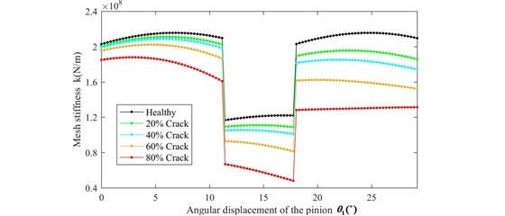
Fig. 5The comparison between analytical method and FEM: a) Healthy condition; b) 20 % crack; c) 40 % crack; d) 60 % crack; e) 80 % crack
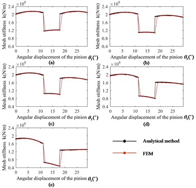
In the perfect condition, the gearmesh stiffness results obtained from the potential energy method and the FEM match significantly well, which validates the accuracy of cantilever beam model on the root circle. With the growth of crack, the gearmesh stiffness results of the proposed exponential curve model agree well with those obtained from FEM. Overall, the gearmesh stiffness equations derived by exponential curve model in this paper can be used to estimate the gearmesh stiffness with root crack if appropriate error of gearmesh stiffness is allowed.
6. Conclusions
In this paper, an exponential curve model based on the Saint Venant’s Principle is proposed for the gearmesh stiffness calculation of cracked gears, and the TVGS results obtained from this model are compared with those of FEM. Conclusions are summarized as follows.
The transition deflection and foundation deflection have a significant influence on the TVGS. Thus, a accurate description of transition curve is of vital importance. In addition, the shape of limiting line plays an important role in calculate bend stiffness and shear stiffness, and the exponentially decayed curve based on the Saint Venant’s Principle is able to explain the stress concentration at the crack tip reasonably. Furthermore, the gearmesh stiffness results of exponential curve model are consistent well with those of FEM well. Therefore, the exponential curve model can be used to estimate the gearmesh stiffness and functions as an alternative to FEM in TVGS calculation
References
-
Chaari F., Fakhfakh T., Haddar M. Dynamic analysis of a planetary gear failure caused by tooth pitting and cracking. Journal of Failure Analysis and Prevention, Vol. 6, 2006, p. 73-78.
-
Cooley C. G., Parker R. G. A review of planetary and epicyclic gear dynamics and vibrations research. ASME Applied Mechanics Reviews, 66, p. 2014-40804.
-
Lei Y., Liu Z., Lin J., Lu F. Phenomenological models of vibration signals for condition monitoring and fault diagnosis of epicyclic gearboxes. Journal of Sound and Vibration, Vol. 369, 2016, p. 266-281.
-
Lei Y., Lin J., Zuo M. J., He Z. Condition monitoring and fault diagnosis of planetary gearboxes: A review. Measurement, Vol. 48, 2014, p. 292-305.
-
Zouari S., Maatar M., Fakhfakh T., Haddar M. Three-dimensional analyses by finite element method of a spur gear: effect of cracks in the teeth foot on the mesh stiffness. Journal of Failure Analysis and Prevention, Vol. 7, 2007, p. 475-481.
-
Pandya Y., Parey A. Experimental investigation of spur gear tooth mesh stiffness in the presence of crack using photoelasticity technique. Engineering Failure Analysis, Vol. 34, 2013, p. 488-500.
-
Yang D., Lin J. Hertzian damping, tooth friction and bending elasticity in gear impact dynamics. ASME Journal of Mechanisms, Transmissions, and Automation in Design, Vol. 109, 1987, p. 189-196.
-
Tian X. Dynamic Simulation for System Response of Gearbox Including Localized Gear Faults. University of Alberta, Edmonton, Alberta, Canada, 2005.
-
Liang X., Zuo M. J., Pandey M. Analytically evaluating the influence of crack on the mesh stiffness of a planetary gear set. Mechanism and Machine Theory, Vol. 76, 2014, p. 20-38.
-
Chen Z., Shao Y. Mesh stiffness calculation of a spur gear pair with tooth profile modification and tooth root crack. Mechanism and Machine Theory, Vol. 62, 2013, p. 63-74.
-
Ma H., Song R., Pang X., Wen B. Time-varying mesh stiffness calculation of cracked spur gears. Engineering Failure Analysis, Vol. 44, 2014, p. 179-194.
-
Christides S., Barr A. One-dimensional theory of cracked Bernoulli-Euler beams. International Journal of Mechanical Sciences, Vol. 26, 1984, p. 639-648.
-
Carneiro S. H., Inman D. J. Continuous model for the transverse vibration of cracked Timoshenko beams. ASME Journal of Vibration and Acoustics, Vol. 124, 2002, p. 310-320.
-
Hou C., Lu Y. Identification of cracks in thick beams with a cracked beam element model. Journal of Sound and Vibration, Vol. 385, 2016, p. 104-124.
Cited by
About this article

This research was supported by National Natural Science Foundation of China (51475355 and 61673311) and National Program for Support of Top-notch Young Professionals.
