Abstract
One of the most important characteristics of construction behavior is physical nonlinearity which appears in the course of deformation between strain and deformations. Its account complicates algorithm; therefore, many modern construction calculations are spent in an elastic stage that lead to the overestimated results, not corresponding to real work of the construction. In this connection, it is necessary to develop such models of construction, which fully enough and unequivocally confirm to investigated objects and processes of their deformation.
1. Introduction
Modern buildings and constructions represent complex structure. The usage of new materials and Nano-technologies, promoting creation of effective construction demands perfection of the theory and calculation methods. Existing construction procedures do not succeed to be developed as promptly as increases complexity of erected constructions [1]. The occurrence of such tendency promotes, including considerable backlog of domestic standard base. Existing now program complexes, especially so-called “heavy class” (ANSYS, NASTRAN etc.) allow carrying out calculations of almost any constructions taking into account physical and geometrical nonlinearity (including simultaneously), taking into account formation of cracks, various deformation diagrams of materials etc. [2]. But at the same time the given program complexes do not allow the engineer-builder to operate mobile calculation taking into account constantly changing parameters of the system and to estimate received results with experimental data [3]. Program complexes of the “average” class (Lyre, MicroFE, etc.) are simpler in mastering for ordinary engineers, but do not allow to look through in details as set initial parameters of calculations (for example, diagram of concrete deformation and algorithms of the account of crack formation), and results of calculation (for example, crack formation on height of the element) [4-6]. That is, the given program complexes hide necessary options and target parameters that does not allow from the user high-grade to verify results of the executed calculations.
2. Materials and methods
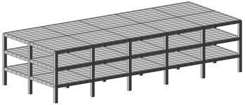
All subsequent researches are carried out on the concrete example. The three-storied office building with the sizes in the plan 12×30 m Fig. 1 is considered. The constructive scheme of the building is a monolithic reinforced-concrete skeleton. The step of columns to longitudinal and cross-section direction is 6 m. The height of the floor is 3 m. The column of the square section with the sizes 40×40 cm crossbars of rectangular section are 35×50 () cm. The plates of overlapping and covering from monolithic reinforced-concrete in the thickness are 20 cm. The concrete grade for all construction is В25. The foundations are monolithic and columnar.
The method of final elements which was realized with application of the computer program Lyre was used for calculation. The basic mathematical operation FEM is formation and solution of the algebraic equations system consisting of the balance equations of each unit of the construction calculation model:
where column-matrix of unknown unit removal, is column-matrix of external loading, stiffness matrix of all calculated construction. This matrix is formed of coefficients of stiffness matrix of separate final elements. At solution of linear problem, it does not change, i.e. .
From Castigliano’s theorems reaction in any connection can be defined as derivative from energy system on removal, i.e.:
where is total energy of the system.
At bend taking into account linear force apparent energy of nod in length and stiffness of bend EI has the form:
where bend of the nod.
Using the method of the final elements, it is possible to present a full-scale deflection in the form:
where ; static deflections of the nod at the beginning and end without linear forces. Full nodal displacement on the three-dimensional space represents a vector consisting from 6 components: (, , , , , ) where first three components represent forward displacement and three subsequent-angular deflections [2].
At solution of the linear problem the stiffness matrix of one element for case of stiffness connection on two ends has the form:
where stiffness at extension-compression; stiffness at the bend; length of the nod.
At solution of the linear problem stiffness matrix of one element in case of stiffness connection of one end and hinged joint of the other end has the form:
The matrix of external central loading for elements of the skeleton of the building has the form:
Fig. 1The calculation model of the building considers following static loadings
The vector of removal of nodal points in the general coordinate frame:
The vector of nodal efforts for element in the general coordinate frame:
The vector of nodal efforts for element in local coordinate frame:
The net thrust in nods of separate elements in local coordinate frame taking into account transformations out of nodal load:
where vector of transformations out of nodal load:
At solution of the nonlinear problem of the combined equations Eq. (1) becomes the form:
where stiffness matrix of the construction with nonlinear properties. During calculation, this matrix should be constantly changed depending on those nonlinear properties which show final elements, i.e. it is achieved by step-by-step construction rewarding and inclusion of iterative process on each step.
For construction of the iterative process it is possible to use one of two variants: to change stiffness matrix and to solve combined equations Eq. (2) on each iteration or to apply method of additional loadings (method of elastic solution).
The stiffness matrix of the construction with nonlinear properties is considered as the sum of two constituents:
where stiffness matrix with linear properties, and nonlinear constituent providing change of this matrix to dimension In condition of limit equilibrium (ultimate behavior) at development of all nonlinear properties, combined equation Eq. (2) gets the form:
where stiffness matrix in the condition of limit equilibrium. Iterative process should be so constructed, that matrix at first turned to matrix and then into for formations of the stiffness matrix it is possible to use approximate methods. The iterative method, where in the deformation course is changed deformation module according to the accepted diagram of behavior of concrete and armature, is used in this work. As variable parameters of elasticity are accepted fictitious (secants) elasticity modules of the concrete steels [4]:
On the first step of value calculation of fictitious modules of elasticity , are accepted equal to their start values. New values of parameters of elasticity are defined under equations:
Functions ; are defined from the accepted deformation diagram of concrete and armature. For the nod, final element taking into account longitudinal, cross-section forces and bending moment change of stiffness matrix for concrete on the 1st step of iteration for 2 and 3 variants of calculation has the form:
3. Results and discussion
Numbering of elements of the skeleton is presented Fig. 1. The total quantity of the nod of system is 2050. Each nod has six degrees of freedom. Further in the littleness force values of rotational moments and corresponding angles of rotation of their value are not presented in corresponding tables and schedules. In the elastic stage of work on Figs. 2-7 are presented color charts of nodal removal. From drawings, it is visible that the greatest removals arise in nods of the top floors. On lower floors owing to the big stiffness of bearing elements these removals are decreased. The tables of internal efforts in specific bearing elements of the construction (Extreme and average columns of the ground floor are given; averages longitudinal crossbar). On the basis of these results diagrams of changes of internal efforts for elastic condition of systems are constructed.
Fig. 2Computed plot of the removal on X
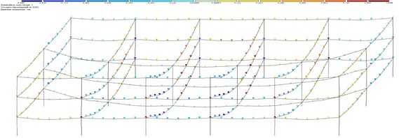
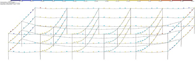
Fig. 3Computed plot of the removal on Y
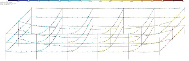
Fig. 4Computed plot of the removal on Z
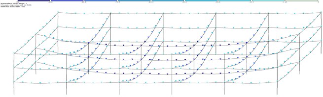
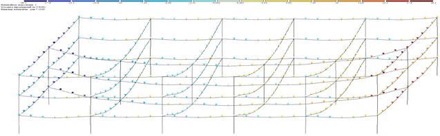
Fig. 5. Computed plot of the removal on
Fig. 6Computed plot of the removal on UY
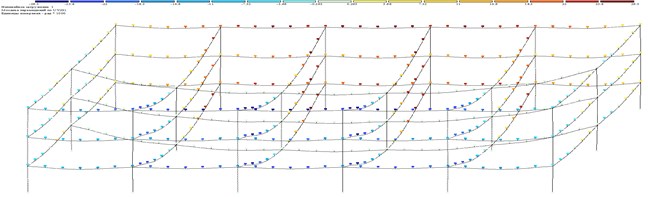
Fig. 7Computed plot of the removal on UZ
4. Conclusions
1) Using the method of final elements, calculation of frame building for 4 variants is made: 1 elastic condition; 2 exponential law of the change between pressure and deformations; 3 piecewise linear law of the change between pressure and deformations; 4 creeps of concrete. Values of nodal forward and angular removal and internal efforts from each kind of deformations are received;
2) The received results of calculation taking into account nonlinearity of materials of the construction is sharply differed from elastic solution that gives evidence about necessity for reception of an authentic picture of bearing elements behavior of the construction to consider physical nonlinearity. Its influence in comparison with geometrical and constructive nonlinearity is more essential (55 % – influence of physical nonlinearity; 30 % – influence of geometrical nonlinearity and 15 % – constructive nonlinearity).
References
-
Sorace Stefano, Terenzi Gloria Analysis, design, and construction of a base-isolated multiple building structure. Advances in Civil Engineering, Vol. 2014, 2014, p. 1-13.
-
Sayani P. J., Erduran E., Ryan K. L. Comparative response assessment of minimally compliant low-rise base isolated and conventional steel moment-resisting frame buildings. Journal of Structural Engineering, Vol. 137, Issue 10, 2011, p. 1118-1131.
-
Agarwal V. K., Niedzwecki J. M., van de Lindt J. W. Earthquake induced pounding in friction varying base isolated buildings. Engineering Structures, Vol. 29, Issue 11, 2007, p. 2825-2832.
-
Mazza F., Mazza M., Vulcano A. Nonlinear dynamic response of RC buildings with different base-isolation systems subjected to horizontal and vertical components of near-fault ground motions. The Open Construction and Building Technology Journal, Vol. 6, 2012, p. 373-383.
-
Musayev Janat, Zhauyt Algazy, Sagatbek Manap, Matikhan Nurali, Kaliyev Yerbol, Naurushev Batyr Seismic resistance of horizontal underground openings in anisotropic rocks. Vibroengineering Procedia, Vol. 8, 2016, p. 231-236.
-
Mazza F., Vulcano A. Effects of near-fault ground motions on the nonlinear dynamic response of base-isolated r.c. framed buildings. Earthquake Engineering and Structural Dynamics, Vol. 41, Issue 2, 2012, p. 211-232.
-
Di Sarno L., Chioccarelli E., Cosenza E. Seismic response analysis of an irregular base isolated building. Bulletin of Earthquake Engineering, Vol. 9, Issue 5, 2011, p. 1673-1702.
-
Martelli A., Forni M. Seismic isolation and other antiseismic systems. Recent applications in Italy and worldwide. Seismic Isolation and Protective Systems, Vol. 1, Issue 1, 2010, p. 75-123.
About this article

