Abstract
To improve the ductility of high-strength concrete and enhance the ductility and load-bearing capacity of steel reinforced high-strength concrete (SRHSC) columns, steel fibers were added to SRHSC to prepare steel and steel fiber reinforced high-strength concrete (SSFRHSC) columns. In order to study the eccentric compression of SSFRHSC columns, based on the experimental study of the eccentric compression of SSFRHSC columns, finite element model specimens of SSFRHSC eccentric columns were established using ABAQUS software, and the accuracy of the model was verified by combining the test results. On the basis of the experiments, the parameters such as steel fiber volume rate, concrete strength and eccentricity distance were further changed to extend the study. The results show that: with the increase of the volume rate of steel fiber from 0.5 % to 3 % and the concrete strength from C40 to C90, the ultimate bearing capacity of the specimen increases by 40.81 % and 58.69 % respectively; at the same time, when the eccentric distance increases from 0 mm to 100 mm, the ultimate bearing capacity of the specimen decreases by 66.76 %, and when the eccentric distance When the eccentricity distance was increased from 0 mm-40 mm to 60 mm-100 mm, the structural damage form changed from brittle damage to ductile damage.
Highlights
- To improve the ductility of high-strength concrete and enhance the ductility and load-bearing capacity of steel section high-strength concrete (SRHSC) columns, steel fibers were added to SRHSC to prepare steel and steel fiber reinforced high-strength concrete (SSFRHSC) columns.
- In order to study the eccentric compression of SSFRHSC columns, based on the experimental study of the eccentric compression of SSFRHSC columns, finite element model specimens of SSFRHSC eccentric columns were established using ABAQUS software, and the accuracy of the model was verified by combining the test results.
- On the basis of the experiments, the parameters such as steel fiber volume rate, concrete strength and eccentricity distance were further changed to extend the study.
1. Introduction
As early as the early 20th century, countries such as Europe, America, and Japan were struggling to meet the demand for high-rise, large-span, and high-performance buildings and structures with insufficient reinforced concrete components. The research on steel reinforced concrete (SRC) began, especially after World War II, many countries adopted SRC structures during the restoration and reconstruction period. At present, the SRC theory is relatively mature, and it is also widely used in engineering. With the continuous development of the global economy, the number of high-rise buildings is increasing, and the requirements for the bearing capacity of structures are also correspondingly increasing. To enhance the bearing capacity of the structure, the strength of the concrete is increased on the basis of the steel reinforced concrete, while the longitudinal bars and hoops are reasonably arranged, namely the SRHSC. In order to improve the deformation capacity of components, steel fiber reinforced concrete (SFRC) is added to the concrete [1-3]. The performance of steel fiber reinforced concrete was studied through experiments and simulations, and it was found that SFRC can effectively resist concrete cracking, thereby enhancing the bearing capacity and ductility of the components. To further enhance the bearing capacity of the components, a combination form –SSFRHSC is formed. In practical engineering, most columns are in a compressive state under the combined action of axial force and bending moment, so it is necessary to study the mechanical performance of SSFRHSC columns under eccentric state.
In this paper, ABAQUS finite element software is used to model the SSFRHSC eccentric compression column test [4] specimen and perform nonlinear analysis (the relevant parameters of the specimen are all referred to the literature [4]), to obtain the load-displacement curves, deformation diagrams, stress cloud diagrams and the main load eigenvalues of the SSFRHSC eccentric columns, etc., and to compare and analyses the simulated data with the experimental data, to validate the accuracy of the model. Then the force performance and damage mechanism of SSFRHSC bias column are analyzed. In addition, on the basis of verifying the accuracy of the model, the parameters of steel fiber volumetric rate, concrete strength, and eccentricity of the model are further varied so as to investigate the mechanical properties of SSFRHSC biased columns and to better guide the related design of such members.
2. Finite element modeling of SSFRHSC biased columns in steel sections
2.1. Steel fiber modeling
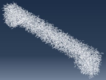
For the modeling of steel fibers, a secondary development in Python on ABAQUS was used to generate the fiber model shown in Fig. 1.
Fig. 1Schematic diagram of steel fiber model
2.2. Constitutive model of materials
The concrete compressive constitutive and peak compressive strains were calculated using the Yu Zhiwu, DING Faxing [5] method to obtain the stress-strain relationship equation:
where, stand for the axial compressive stress in concrete; refer to peak strain corresponding to peak compressive stress; is ratio of initial modulus of elasticity to peak cutline modulus of concrete; is descending section parameters.
In this paper, the stress-strain relationship equation of Ding Faxing, Yu Zhiwu calculation method [6] is used for the tensile constitutive structure and peak tensile strain of concrete:
where, stand for axial tensile strength; is strain corresponding to peak tensile stress; and is respectively the ascent and descent section parameters.
In this paper, Najar energy damage theory [7] is used to calculate the damage factor , which is calculated as:
where, , and is respectively the damage factors, initial modulus of elasticity and stress-strain curve equation.
In this paper, we combine the characteristics of SSFRHSC biased columns and choose the failure criterion proposed by Zhenhai Guo et al. [8], which are given by:
where, is the limit value of when approaches ; stand for coordinate value of the intersection point between the meridian and the abscissa; refer to meridian parameters at different angles ; is coordinate value of the intersection point between tangent and abscissa.
The steel fiber and steel reinforcement adopt a double line model:
where, and is respectively initial elastic modulus and post yield elastic modulus of steel.
This article uses Eq. (6) and (7) to convert experimental data. Calculate the plastic strain value using Eq. (8):
where, and stands for nominal stress and nominal strain; , and is respectively true plasticity, overall and true elastic strain values.
2.3. Model meshing and interaction
C3D8R solid units are used for steel and concrete components; the steel bars and steel fiber components use T3D2 truss units.
This article selects a grid side length of 0.02 m for concrete columns, 0.025 m for steel profiles, 0.048 m for steel reinforcement cages, and 0.035 m for steel fibers. The finite element model mesh division diagram of each element component of the composite column is shown in Fig. 2.
Considering the contact relationship between the steel section and the concrete interface in the real situation, the volume part of the steel section is deducted from the inside of the concrete when modelling the concrete, and then the contact between the outer surface of the steel section and the interface of the concrete is set, where the Specify tolerance for adjustment zone is set to 0.0001, and Normal Behavior is set to Hard Contact, define the friction with penalty function, the coefficient is set to 0.5, after calculation and comparison, this way is more accurate than directly embedding the steel section in concrete. The Embedding region is used for the action relationship of steel cage, steel fiber and concrete column respectively.
Fig. 2Grid partition diagram of each component of combined column
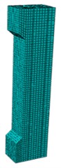
a) Concrete

b) Steel fiber
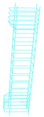
c) Rebar cage
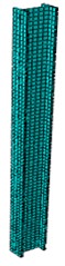
d) Section steel
3. Analysis of finite element calculation results for SSFRHSC bias column
3.1. Finite element model validation
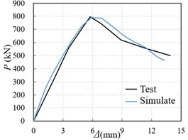
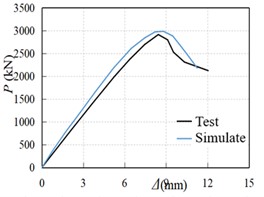
Fig. 3 is a comparison of the load-displacement curves obtained by simulating the six specimens used in the literature [4]. As can be seen from Fig. 1, the load-displacement curves of the test specimens and the simulated specimens are in good agreement, and the peak load difference is within 10 %, which indicates that the simulation effect and the test are in good agreement.
Fig. 3Comparison of calculated load-displacement curve and test curve of section steel fiber high-strength concrete column
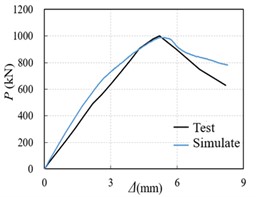
a) SSFRHSC-1 test-piece
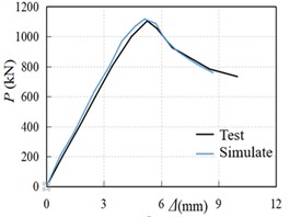
b) SSFRHSC-2 test-piece
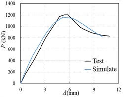
c) SSFRHSC-3 test-piece
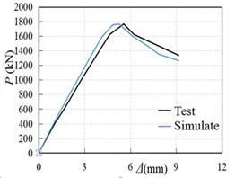
d) SSFRHSC-4 test-piece
e) SSFRHSC-5 test-piece
f) SSFRHSC-6 test-piece
3.2. Finite element expansion analysis
In order to more comprehensively study the mechanical properties of steel fiber reinforced high-strength concrete columns under eccentric compression, and better guide the related design of such members, based on the correctness of the model, the model expansion analysis was carried out on the influence parameters such as steel fiber volume ratio, concrete strength, eccentricity, slenderness ratio, and other parameters of the specimen remained unchanged. See Table 1 for dimensions of simulated components.
Table 1Specimen design
Component number | Concrete strength grade | Fiber volume ratio /% | Eccentricity (mm) | Dimension (mm²) | Column height (mm) |
S-1-A1 | C90 | 1 % | 80 | 180×220 | 1400 |
S-1-A2 | C90 | 1.5 % | 80 | 180×220 | 1400 |
S-1-A3 | C90 | 2 % | 80 | 180×220 | 1400 |
S-1-A4 | C90 | 2.5 % | 80 | 180×220 | 1400 |
S-1-A5 | C90 | 3 % | 80 | 180×220 | 1400 |
S-5-B1 | C80 | 0.5 % | 40 | 180×220 | 1400 |
S-5-B2 | C70 | 0.5 % | 40 | 180×220 | 1400 |
S-5-B3 | C60 | 0.5 % | 40 | 180×220 | 1400 |
S-5-B4 | C50 | 0.5 % | 40 | 180×220 | 1400 |
S-5-B5 | C40 | 0.5 % | 40 | 180×220 | 1400 |
S-4-C1 | C90 | 0.5 % | 20 | 180×220 | 1400 |
S-4-C2 | C90 | 0.5 % | 40 | 180×220 | 1400 |
S-4-C3 | C90 | 0.5 % | 60 | 180×220 | 1400 |
S-4-C4 | C90 | 0.5 % | 80 | 180×220 | 1400 |
S-4-C5 | C90 | 0.5 % | 100 | 180×220 | 1400 |
Fig. 4 shows the simulation results of five specimens with different steel fiber volume rates. It can be seen from Fig. 4 that the ultimate bearing capacity of the specimens increases by 10.11 %, 9.27 %, 6.48 %, 6.09 % and 3.53 % for each 0.5 % increase in fiber rate from 0.5 % to 3 %, and that steel fibers improve the ductility of the specimens.
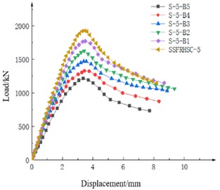
Fig. 5 shows the simulation results for five different concrete strength specimens. It can be seen from Fig. 5 that the peak loads of the specimens increased by 9.39 %, 10.73 %, 10.46 %, 9.12 % and 8.68 % for each increase in concrete strength from C40 to C90, respectively.
Fig. 4Load-displacement curves of specimens with different steel fiber volume ratios
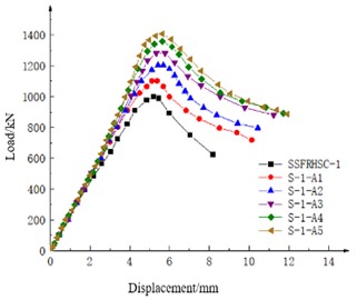
Fig. 5Load-displacement of concrete specimens with different strength
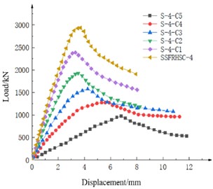
As shown in Fig. 6, the load displacement curves of six simulated specimens with different eccentricities can be seen from the figure: the specimens with eccentricities of 0 mm, 20 mm and 40 mm are brittle failure, and the bearing capacity decreases rapidly after the column reaches the peak load. The specimens with eccentricity of 60 mm, 80 mm and 100 mm are ductile failure. When the column reaches the peak load, the falling section is relatively gentle. It can be seen from Fig. 6 that with the eccentricity from 0 to 100 mm, the peak load of the test piece decreases by 18.66%, 19.35 %, 18.23 %, 18.99 % and 21.52 % for each 20 mm increase.
Fig. 6Influence of RC column damage degree on load-displacement curve of specimen
4. Conclusions
The following conclusions are drawn in this paper.
1) The steel fiber volume ratio of SSFRHSC columns ranged from 0 % to 1 %. For each increase of 0.5 %, the peak load increased by 9.47 % and 9.79 % respectively, and the corresponding vertical displacement of peak load increased by 6.50 % and 2.51 % respectively. With the increase of eccentricity from 0 mm to 120 mm, the peak load showed a downward trend of 39.80 %, 38.69 % and 32.70 % respectively, and each increase of 40 mm eccentricity would further reduce the load.
2) When the steel fiber content increases from 0.5 % to 3 %, the ultimate bearing capacity increases by 10.11 %, 9.27 %, 6.48 %, 6.09 % and 3.53 %, respectively. When the steel fiber volume ratio is 2 %, the effect of increasing the steel fiber content on the ultimate bearing capacity of the specimen gradually decreases. With the increase of concrete strength, the ultimate bearing capacity of the specimen increases, and the deformation capacity decreases slightly. From C40 to C90, the peak load of the specimen increases by 9.39 %, 10.73 %, 10.46 %, 9.12 % and 8.68 % for each grade of concrete strength. The specimen whose eccentricity is less than 40 mm is brittle failure, and the bearing capacity decreases rapidly after the column reaches the peak load. The specimens with an eccentricity of 40 mm turn to ductile failure. When the column reaches the peak load, the falling section is relatively gentle. The peak load of the specimen decreases by 18.66 %, 19.35 %, 18.23 %, 18.99 % and 21.52 % for each 20 mm increase in the eccentricity from 0 to 100 mm.
References
-
I. Trabucchi, G. Tiberti, A. Conforti, F. Medeghini, and G. A. Plizzari, “Experimental study on steel fiber reinforced concrete and reinforced concrete elements under concentrated loads,” Construction and Building Materials, Vol. 307, No. 6, p. 124834, Nov. 2021, https://doi.org/10.1016/j.conbuildmat.2021.124834
-
Y. W. Shewalul, “Numerical and FEA investigation of sectional capacity and moment redistribution behavior of steel fiber reinforced concrete (SFRC) beam,” Heliyon, Vol. 7, No. 6, p. e07354, Jun. 2021, https://doi.org/10.1016/j.heliyon.2021.e07354
-
C. Pradeep Kumar and M. Shahul Hameed, “Experimental study on the behaviour of steel fibre when used as a secondary reinforcement in reinforced concrete beam,” Materials Today: Proceedings, Vol. 52, No. 3, pp. 1189–1196, 2022, https://doi.org/10.1016/j.matpr.2021.11.033
-
Z. Li et al., “Experimental study on steel fiber reinforced high strength concrete columns under eccentric compression,” (in Chinese), Journal of Applied Mechanics, Vol. 38, No. 4, pp. 1676–16830, 2021.
-
Y. Zhiwu and D. Faxing, “Unified calculation method for mechanical properties of concrete under compression,” (in Chinese), Journal of Building Structures, Vol. 24, No. 4, pp. 41–46, 2003.
-
D. Faxing and Y. Zhiwu, “Unified calculation method for tensile properties of concrete,” (in Chinese), Journal of Huazhong University of Science and Technology (Urban Science Edition), Vol. 21, No. 3, pp. 29–34, 2004.
-
H. Qin and X. Zhao, “Research on ABAQUS concrete damage factor selection method,” (in Chinese), Structural Engineer, Vol. 29, pp. 27–32, 2013.
-
Z. Guo et al., “Study on multiaxial strength test and failure criterion of concrete (sixth volume of Scientific Research Report),” (in Chinese), Scientific Research Report, Tsinghua University Press, 1996.
About this article

The authors have not disclosed any funding.
The datasets generated during and/or analyzed during the current study are available from the corresponding author on reasonable request.
The authors declare that they have no conflict of interest.
