Abstract
The paper presents the results of computational analysis of the stress-strain state of reinforced concrete spans of the railway (single-track railway line) overpass over the highway, under specified loads using spatial finite element models. The static load consists of a cohesion of three TEM-18 diesel locomotives and two loaded gondola cars (up to 25 tons per axle). The purpose of this study was to ensure reliable and safe operation of artificial structures on the railroads, as there is a constant increase in transit freight trains from China through the territory of Kazakhstan to near and far abroad, and often the load on the axle reaches 25 tons, and sometimes larger values – up to 27 tons per axle. The results of the study are recommended to be used for inspections and tests of typical girder bridge spans, as well as in the case of monitoring their technical condition with increasing operational loads.
Highlights
- Problems of repair and maintenance of railway overpasses
- Railway rolling stock circulating on the main networks of Kazakhstan
- Internal stresses arising in elements of railway reinforced concrete structures under the influence of transport load
1. Introduction
Railway transportation facilities are unique systems that function in extremely diverse natural and climatic conditions [1-3]. Ensuring the safe operation of this system is a complex and multifaceted task [5-10]. Maintaining the railroad track and artificial structures in a safe technical condition is the main task of the operational service [11-12]. In order to predict the failure-free service life of artificial structures on railroads, calculation models are made, which can take into account the defects that appeared during the operation [13-14]. The data obtained when performing calculations of the spatial finite element model of a reinforced concrete overpass in the program “ABAQUS/Standard” are in agreement with the data obtained during in-situ tests of a reinforced concrete railway overpass. In the works of foreign [15-18] Russian [19] and Kazakhstani [20, 21] specialists presented studies on experimental determination of the stress-strain state of girder spans of railway bridges, confirming the adequacy of the results presented in this article.
1.1. Materials and methods of research
1.1.1. Description of the calculation model
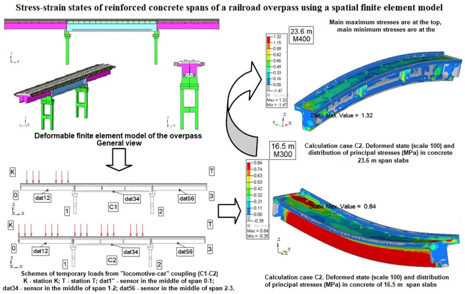
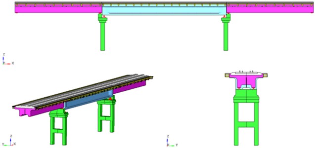
The calculation model for stress-strain state (SS) and modal analysis of the structure is built according to the data provided in the form of working documentation for the considered transportation structure. The general view of the calculation model of the considered reinforced concrete overpass is presented in Fig. 1. The model of the reinforced concrete overpass takes into account the joint operation of reinforcing elements and concrete filling. The concrete filling of the structures of reinforced concrete blocks of 16.5 m and 23.6 m spans. Reinforcing elements of structures (frames, meshes, bundles of wires for concrete prestressing) of flyover structures and structures of intermediate supports are specified by rod elements and take into account their spatial arrangement in the concrete filling.
Fig. 1Deformable finite element model of the overpass. General view
1.1.2. 23.6 m span block
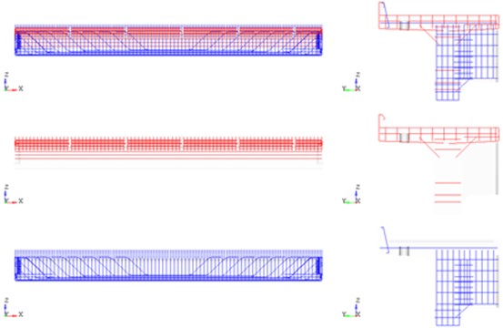
The model of the 23.6 m span block consists of: finite element mesh of the concrete block, taking into account the presence of holes for drainage pipes (Fig. 2). The reinforcing elements (Fig. 3) are grouped according to the assigned classes: tensile reinforcement (bundles of 24 wires Ø5 BII with installation in the concrete mass by means of frame-rod anchors); reinforcement of classes AI, AII.
Fig. 2Deformable finite element model of the 23.6 m span block. Concrete
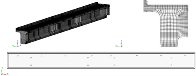
Fig. 3Deformable finite element model of a 23.6 m span block. Reinforcing structures
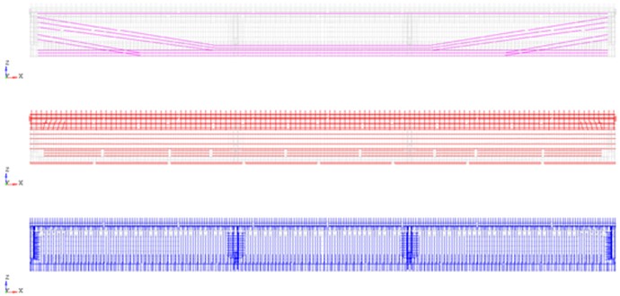
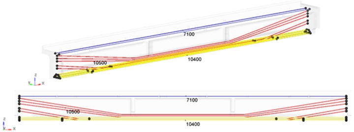
For 23.6 m span blocks made of prestressed reinforced concrete the stresses in reinforcing bundles are set (Fig. 4): upper rectilinear bundles 7100 kgf/cm2; polygonal bundles 10500 kgf/cm2; lower rectilinear bundles 10400 kgf/cm2.
Fig. 4Deformable finite element model of the 23.6 m span. Frame-rod anchors and controlled stresses (kgf/cm2) in reinforcement bundles
1.1.3. 16.5 m span block
The model of the 16.5 m span block consists of: finite element mesh of the concrete block, taking into account the presence of holes for drainage pipes (Fig. 5). The reinforcing elements (Fig. 6) are allocated in groups according to the assigned classes AI, AII.
Fig. 5Deformable finite element model of a 16.5 m span block. Concrete
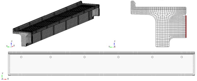
Fig. 6Deformable finite element model of a 16.5 m span block. Reinforcing structures
1.1.4. Loads
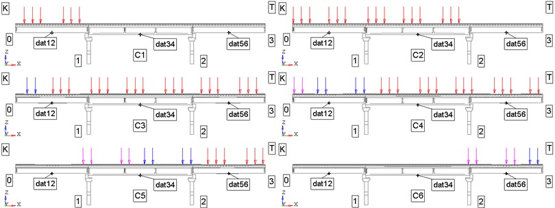
Own weight of the structure structures is taken into account by setting the inertial load – gravity. Temporary loads are set as static loads from the weight of the coupling according to the scheme “locomotive – wagon”. The impact from the weight of the locomotive (cohesion of three TEM-18 diesel locomotives, 2 bogies, 3 axles per bogie) is set in the form of concentrated forces of 20.83 tf/axle in the nodes of the model of the railroad track in accordance with the distances: 16900 mm between the ages of the couplers; 8800 mm between the bogie pins; 1850 mm between the bogie axes. The impact from the weight of cars (2 gondola cars, each with 2 bogies, 2 axles per bogie) is set in the form of concentrated forces 25,0875 tf/axle (gondola car close to the locomotive) and 24,5625 tf/axle (tail gondola car) in the nodes of the model of the railroad track in accordance with the distances: 13920 mm between the axles of the couplers; 8650 mm between the bogie pins (wagon base); 1850 mm between the bogie axles. The considered schemes of temporary loads are presented in Fig. 7 (a total of 6 schemes for locomotive-car coupling).
Fig. 7Schemes of temporary loads from “locomotive-car” coupling (C1-C6): K – station K; T – station T; dat1 – sensor in the middle of span 0-1; dat34 – sensor in the middle of span 1-2; dat56 – sensor in the middle of span 2-3
1.1.5. Research results
Calculations of the stress-strain state of 16.5 m and 23.6 m spans were performed for given load combinations (7 design cases): P0. “23.6 m block reinforcement tension + Own weight”; “P0 + coupling (middle of the 1st section of the locomotive over the middle of PS0-1)”; “P0 + coupling (3rd axis of the 4th bogie of the locomotive over the middle of PS0 1)”; “P0 + coupling (the middle of the 1st section of the locomotive over the middle of PS2-3)”; “P0 + coupling (the 1st axis of the 1st carriage over the support 0)”; “P0 + coupling (the 1st axis of the 1st carriage over the support 3)”; “P0 + coupling (the 2nd axis of the 2nd carriage over the middle of PS2 3)”. The control points are chosen on the lower belt in the middle sections of the structure spans.
The results of calculations of the structure elements under the given loads are presented in the form of distributions of deformations and stresses in the reinforcement and concrete of the overpass span blocks for the design case C4 (Fig. 8-9) at the control points of the virtual sensors (Table 1).
Table 1Design stresses of 16.5 m and 23.6 m spans
No. of loads | No. of stage | PS 0-1 16.5 m | PS 1-2 23.6 m | PS 2-3 16.5 m | |||
Right block | Left block | Right block | Left block | Right block | Left block | ||
1 | 0 | 0 | 0 | 0 | 0 | 0 | 0 |
2-С1 | 1 | 4,78 | 4,78 | 0 | 0 | 0 | 0 |
3-С2 | 2 | 5,40 | 5,40 | 3,83 | 3,83 | 0 | 0 |
4-С3 | 3 | 6,01 | 6,01 | 3,88 | 3,88 | 4,83 | 4,83 |
5-С4 | 4 | 4,64 | 4,64 | 3,72 | 3,72 | 5,33 | 5,33 |
6-С5 | 5 | 0,22 | 0,22 | 3,66 | 3,66 | 4,88 | 4,88 |
7-С6 | 6 | 0 | 0 | 0 | 0 | 5,16 | 5,16 |
8 | 7 | 0 | 0 | 0 | 0 | 0 | 0 |
Notes: 1 and 8 pp (stages 0 and 7) – no load; PS 0-1, 2-3 E=30890 MPa; PS 1-2 E=34320 MPa | |||||||
Fig. 8Calculation case C4. Deformed state (scale 100) and distribution of axial stresses (MPa) in reinforcement of 16.5 m and 23.6 m span slabs
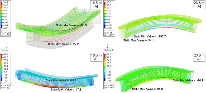
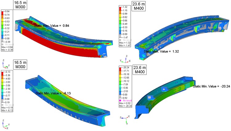
Fig. 9Calculation case C4. Deformed state (scale 100) and distribution of principal stresses (MPa) in concrete of 16.5 m and 23.6 m span slabs. Main maximum stresses are at the top, main minimum stresses are at the bottom
2. Conclusions
Based on the results of the performed research, the following conclusions can be drawn:
1) The obtained stresses in reinforced concrete spans of the railway overpass are within the permissible range, sufficient for safe technical operation of transportation facilities on the railroads of the Republic of Kazakhstan, near and far abroad countries, taking into account similar (typical) elements.
2) The revealed differences in the numerical values of stresses in the elements of the railroad overpass (right and left block) are the formation of defects (conditional creation of uneven wear of structures from the effects of climatic factors).
3) The obtained results of stresses in the elements of the railroad overpass can be used in the design of new facilities, repair and strengthening of operating facilities, as well as in full-scale tests.
The safety of transportation infrastructure facilities depends on the application of advanced technologies and scientific methods to solve complex spatial problems. The use of digital program complexes significantly reduces the costs of current maintenance of artificial structures.
References
-
R. Li, Q. He, S. Zhu, J. Yan, and W. Zhai, “A new methodology for pre-camber design of a long-span bridge considering dynamic train load and complex environmental effects,” Engineering Structures, Vol. 302, p. 117349, Mar. 2024, https://doi.org/10.1016/j.engstruct.2023.117349
-
W. Zhou et al., “Analysis of Key influencing factors of track dynamic irregularity induced by earthquakes in the high-speed railway track-bridge system,” International Journal of Structural Stability and Dynamics, Vol. 2450246, Feb. 2024, https://doi.org/10.1142/s0219455424502468
-
B. Wei, H. Tan, L. Jiang, B. Xiao, and A. Lu, “Shaking table test of the seismic performance for railway simply-supported girder bridge isolated by self-centering bearing,” Engineering Structures, Vol. 300, p. 117249, Feb. 2024, https://doi.org//10.1016/j.engstruct.2023.117249
-
L. Wang, X. Zhang, Y. Han, H. Liu, P. Hu, and C. S. Cai, “A fast hybrid algorithm for the random vibration analysis of train-bridge systems under crosswinds,” Engineering Structures, Vol. 299, p. 117107, Jan. 2024, https://doi.org/10.1016/j.engstruct.2023.117107
-
M. R. Kaloop and J. W. Hu, “Dynamic performance analysis of the towers of a long-span bridge based on GPS monitoring technique,” Journal of Sensors, Vol. 2016, pp. 1–14, Jan. 2016, https://doi.org/http://dx.doi.org/10.1155/2016/7494817
-
N. Bonessio, G. Lomiento, and G. Benzoni, “damage identification procedure for seismically isolated bridges,” Structural Control and Health Monitoring, Vol. 19, No. 5, pp. 565–578, Mar. 2011, https://doi.org/https://doi.org/10.1002/stc.448
-
Y. Yang, Q. Li, and B. Yan, “Specifications and applications of the technical code for monitoring of building and bridge structures in China,” Advances in Mechanical Engineering, Vol. 9, No. 1, p. 168781401668427, Jan. 2017, https://doi.org/http://doi.org/10.1177/1687814016684272
-
S. A. Bokarev, L. Y. Solov’Ev, and E. V. Rogova, “Methodology of steel reinforced concrete railroad span structures load-carrying capacity estimation,” Izvestiya Vuzov. Construction, Vol. 3, pp. 106–114, 2009.
-
A. Belyi, E. Karapetov, and Y. Efimenko, “Structural health and geotechnical monitoring during transport objects construction and maintenance (Saint-Petersburg example),” Procedia Engineering, Vol. 189, pp. 145–151, Jan. 2017, https://doi.org/https://doi.org/10.1016/j.proeng.2017.05.024
-
W. Lienhart and M. Ehrhart, “State of the art of geodetic bridge monitoring,” in Structural Health Monitoring 2015, Jan. 2015, https://doi.org/https://doi.org/10.12783/shm2015/58
-
A. Akbayeva et al., “Development of safety methods on artificial structures of railway lines,” Eastern-European Journal of Enterprise Technologies, Vol. 6, No. 1 (120), pp. 43–52, Dec. 2022, https://doi.org/https://doi.org/10.15587/1729-4061.2022.269964
-
Lanis A., Razuvaev D., and Lomov P., “Conjugation of approach fill with bridge and overbridge,” The Russian Automobile and Highway Industry Journal, Vol. 2, No. 48, pp. 110–120, 2016, https://doi.org/https://doi.org/10.26518/2071-7296-2016-2(48)-110-120
-
Bondar I. S., Makhmetova N. M., and Kvashnin M. Ya. S., “Determination of stressed state and dynamic coefficients of girder bridges,” Vestnik of Siberian State University of Railway Engineering, Vol. 4, No. 67, pp. 92–100, 2023.
-
J. Shi, H. Shi, Z. Wu, and J. Li, “An on-board damage detection method for heavy-haul railway bridge based on sensitivity analysis of bogie responses,” IEEE Sensors Journal, Vol. 24, No. 4, pp. 4642–4655, Feb. 2024, https://doi.org/10.1109/jsen.2023.3342164
-
J. Sánchez-Haro, B. Fernández, G. Capellán, and E. Merino, “Simplified method to detect resonance effects in railway bridges. Viaduct over Aragón River and Almonte bridge application,” Engineering Structures, Vol. 305, p. 117668, Apr. 2024, https://doi.org/10.1016/j.engstruct.2024.117668
-
B. Wu, Y. Ouyang, H.-P. Chen, Z. Guo, and L. Ren, “Distributed stiffness assessment of bridges based on macro-strain envelope curve under moving trainloads,” Structures, Vol. 61, p. 106142, 2024.
-
F. Meng, “Algorithm and control of influence of large elevated station bridge on settlement of adjacent high-speed railway,” Journal of Railway Engineering Society, Vol. 39, No. 12, pp. 66–72, 2023.
-
Z. Zhang, J. Wu, C. Zhang, Y. Chen, and Z. Wang, “Identification of effective prestress of steel strand based on blind-hole method,” Tiedao Xuebao/Journal of the China Railway Society, Vol. 45, No. 8, pp. 166–175, 2023.
-
S. A. Bokarev, A. N. Yashnov, I. I. Snezhkov, and A. V. Slyusar, “Small-size automated systems for diagnostics of ISOS,” Railroad and Track Facilities, Vol. 9, pp. 25–26, 2007.
-
S. S. Abdullayev, I. S. Bondar, G. B. Bakyt, G. K. Ashirbayev, A. M. Budiukin, and Y. Y. Baubekov, “Interaction of frame structures with rolling stock,” in Series of Geology and Technical Sciences, Vol. 445, National Academy of Sciences of the Republic of Kazakshtan, 2021, pp. 22–28, https://doi.org/https://doi.org/10.32014/2021.2518-170x.3
-
Abdullayev S., Bakyt G., Aikumbekov M., Bondar I., and Auyesbayev Ye, “Determination of natural modes of railway overpasses,” Journal of Applied Research and Technology, Vol. 19, pp. 1–10, 2021.
Cited by
About this article

The authors have not disclosed any funding.
The datasets generated during and/or analyzed during the current study are available from the corresponding author on reasonable request.
The authors declare that they have no conflict of interest.
