Abstract
In order to study the stress of two new types of rigid hangers (circular steel and flat-plate rigid hangers) on the railway arch bridges, a finite element model of a railway through arch bridge was established. The influences of different types and sizes of hangers on the dynamic characteristics of the bridge were compared. Based on the established vehicle-bridge coupling vibration model, the influences of circular steel and flat-plate hanger sizes on the stress amplitude of hanger were discussed when the train passes through the bridge. The results show that when the flexible hanger of arch bridge was replaced by the rigid hanger, the symmetrical vertical bending frequency of bridge significantly increased. With the change of the size of flat-plate hanger, the torsional mode of the bridge was doped with the local vibration of the flat-plate hanger. With the increase of circular steel hanger diameter, the maximum stress amplitude of the hanger decreases as a whole. As for the flat-plate hanger, when the long side size is the same, the maximum stress amplitude of the hanger decreases with the increase of the short side size . When the short side size is the same, with the increase of the long side size , the maximum stress amplitude of the shorter hanger decreases, and the maximum stress amplitude of the longer hanger increases. When the size of the flat-plate hanger is too small or too large, the maximum stress amplitude is large.
Highlights
- Based on the established vehicle-bridge coupling vibration model, the influences of different rigid hangers on the stress amplitude of hanger of arch bridge are analyzed.
- The symmetrical vertical bending frequency of arch bridge significantly increases, when the flexible hanger is replaced by the rigid one.
- With the increase of circular steel hanger diameter, the maximum stress amplitude of the hanger decreases as a whole.
- When the size of the flat-plate hanger is too small or too large, the maximum stress amplitude is large.
1. Introduction
With the spans of the bridge increasing further, the slenderness ratios of some key components on the bridge enlarge. Since the components are usually made of steel, they are prone to various harmful vibration for its light weight and small damping ratio. Hence, the damage to components may be caused in a short time, affecting the service life of bridges and even endangering the safety of the whole bridge [1, 2].
The vibration of the bridge would be caused by the vehicle passing through the bridge, and the vibration would affect the movement of the vehicle in return. The excessive vibration of the bridge has negative effects on the safety and comfort of the vehicle running on the bridge [3-5]. In addition, due to dynamic action of the vehicle, the vibration of bridges may lead to the fatigue of structure components [6-8]. As railway transportation has the characteristics of heavy loads and obvious vehicle-induced vibration, the large structural stiffness and high durability of both overall structure and components are often required [9-11]. Flexible hanger, commonly used in highway arch bridges, are limited in the application to railway arch bridges, for the disadvantages of small stiffness, easy corrosion and needing to be replaced. Therefore, rigid hangers have been utilized more and more in the railway arch bridges in recent years. Currently, H-section and rectangular-section rigid hangers are frequently used in railway bridges, and the research on the hangers are basically about these two types [12-14]. Circular steel solid and flat-plate hangers are two novel types of rigid hangers, which have a small quantity of applications [15, 16]. The study on these two types of hangers in railway bridges is still rare. Comparing to the flexible hanger, the rigid hanger have the advantages of not only large stiffness but the remarkable durability as well, which would bring about the great applications to the railway arch bridges. To study the stress of the two novel rigid hangers caused by the vehicle passing the bridge, the dynamic analysis of the vehicle-bridge coupling system is urgently needed.
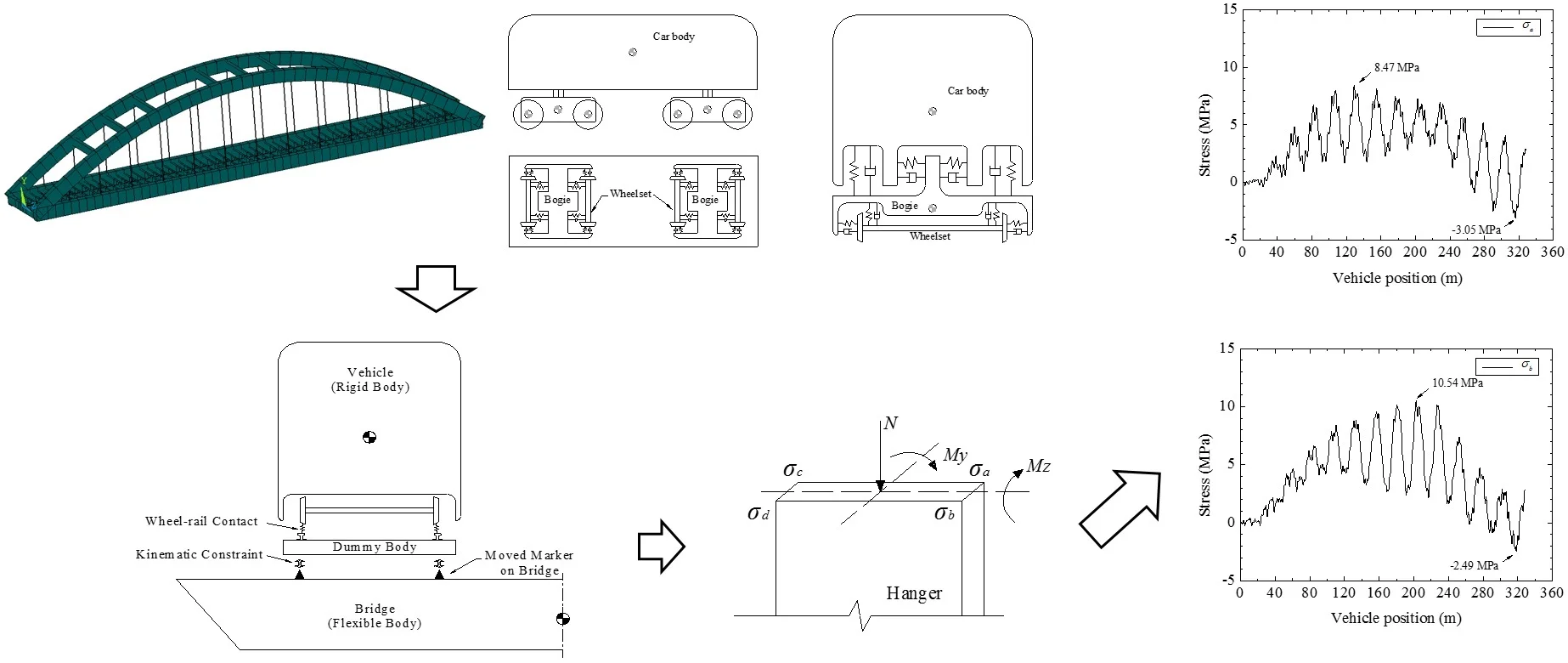
In this paper, a railway through arch bridge was taken as the research project. The finite element (FE) model of the bridge was established, and the influences of different hangers on the dynamic characteristics of the bridge were studied. Furthermore, based on the vehicle-bridge coupling vibration model, the stress amplitudes of hanger during train passing the bridge were studied.
2. Engineering background
Taking a 128 m railway through tied arch bridge as the research project, the dynamic characteristics of the arch bridges with circular steel and flat-plate hanger were studied by changing the type and the size of hangers. And the effects of different sizes on the stress amplitude of hangers when trains pass through the bridge were discussed.
The railway line on the bridge is designed with a speed of 250 km/h. The rise of the arch bridge is 24 m and there are 13 pairs of hangers. And 9 transverse braces are set between the arch ribs. The deck of the bridge is made of steel deck with inverted T-shaped longitudinal girder, T-shaped longitudinal rib and plate rib.
3. Effects of different types of hangers on dynamic characteristics of arch bridges
As the key component of arch bridge, the size of hanger would affect the frequency and mode shape of arch bridge. In the study, three different types of hanger, including flexible hanger, circular steel solid hanger and flat-plate hanger, were compared on the effects on the dynamic characteristics of arch bridge. Nine different hangers (Cases A1 to A9) were investigated to discuss the effects on the dynamic characteristics, the detailed hanger parameters are shown in Table 1. It should be noted that the ratio of height to width of the flat-plate hanger is from 1:4 to 1:8.
Table 1Hanger parameters
Case | Hanger type | Diameter (m) or side length (m) | |
Width | Height | ||
A1 | Flexible hanger | 0.10 | |
A2 | Circular steel solid hanger | 0.10 | |
A3 | 0.20 | ||
A4 | 0.30 | ||
A5 | Flat-plate hanger | 0.30 | 0.0375 |
A6 | 0.30 | 0.050 | |
A7 | 0.30 | 0.075 | |
A8 | 0.45 | 0.075 | |
A9 | 0.60 | 0.075 | |
Commercial FE analysis software ANSYS was used to establish the FE model of the whole bridge. Spatial beam elements were used to simulate arch ribs, transverse braces and longitudinal and transverse beams. And spatial beam elements were used to establish bridge deck by single main girder. As for the hanger, the spatial bar elements were used to simulate flexible hangers, while the spatial beam elements were used to simulate the rigid hangers (circular steel solid hanger and flat-plate hanger). The finite element model of the bridge is shown in Fig. 1.
Through the dynamic characteristics analysis, the typical mode shapes and the corresponding natural vibration frequency of bridges are listed in Table 2. And the relative difference in Table 2 refers to the relative change rate comparing the frequency of the bridge with rigid hanger (Cases A2 to A9) to the frequency of the bridge with flexible hanger (Case A1).
Fig. 1Finite element model of bridge
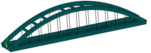
Table 2Comparisons on natural vibration characteristics of different types of hanger on the arch bridge
Case | 1st symmetric transverse bending of arch ribs | 1st symmetric vertical bending of main girder | 1st asymmetric vertical bending of main girder | 1st torsion of arch ribs and main girder | ||||
Frequency (Hz) | Relative difference | Frequency (Hz) | Relative difference | Frequency (Hz) | Relative difference | Frequency (Hz) | Relative difference | |
A1 | 0.8782 | – | 1.4382 | – | 1.6797 | – | 1.9187 | – |
A2 | 0.8758 | –0.27 % | 2.0883 | 45.20 % | 1.6739 | –0.35 % | 1.9192 | 0.03 % |
A3 | 0.8658 | –1.41 % | 2.1670 | 50.67 % | 1.6566 | –1.38 % | 1.8851 | –1.75 % |
A4 | 0.8661 | –1.38 % | 2.1880 | 52.13 % | 1.6328 | –2.79 % | 1.8534 | –3.40 % |
A5 | 0.8720 | –0.71 % | 2.1380 | 48.66 % | 1.6730 | –0.40 % | 1.9120 | –0.35 % |
A6 | 0.8700 | –0.93 % | 2.1659 | 50.60 % | 1.6700 | –0.58 % | 1.9039 | –0.77 % |
A7 | 0.8650 | –1.50 % | 2.1910 | 52.34 % | 1.6659 | –0.82 % | 1.8780 | –2.12 % |
A8 | 0.8550 | –2.64 % | 2.2030 | 53.18 % | 1.6641 | –0.93 % | 1.9060 | –0.66 % |
A9 | 0.8460 | –3.67 % | 2.2050 | 53.32 % | 1.6689 | –0.64 % | 1.8111 | –5.61 % |
When the flexible hanger of the bridge was replaced by the rigid hanger, the first-order symmetric vertical bending frequency of the bridge changes greatly. The frequency increases from 1.4382 Hz to about 2.1 Hz to 2.2 Hz for circular steel solid hanger and flat-plate hanger, respectively. The relative difference is more than 40 % and 45 %. The other three frequencies change little, whose differences are basically less than 5 %.
The change of the diameter of circular steel solid hanger has influences on the vertical bending and torsion, but the relative difference are still less than 5 %. With the increase of hanger diameter, the frequencies of symmetric transverse bending, asymmetric vertical bending and torsion decrease, while the frequencies of symmetric vertical bending increase. It is because with the increase of diameter, the stiffness of hangers increases, the overall stiffness distribution and force transfer change due to the change of local stiffness. Moreover, the self-weight of the structure will increase as well.
The change of the size of flat-plate hanger has effects on torsion frequency, but the maximum relative difference is only 5.6 %. With the increase of the size of flat-plate hanger, the symmetry transverse bending frequency decreases and symmetry vertical bending frequency increases.
Fig. 2Comparisons on torsional mode shape of the arch bridge with circular hanger and flat-plate hanger
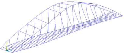
a) Case A2
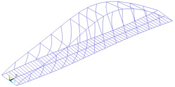
b) Case A5
The change of the diameter of circular steel solid hanger has no obvious effects on the mode shapes of the bridge. However, as for the flat-plate hanger, with the increase of the hanger size, the local vibration of the hanger join more in the torsional mode shape of bridge, and the torsional mode of the bridge is less obvious. The comparisons of torsional mode shapes of Case A2 (circular steel hanger) and Case A5 (flat-plate hanger) are shown in Fig. 2.
4. Vehicle-bridge system coupling vibration model
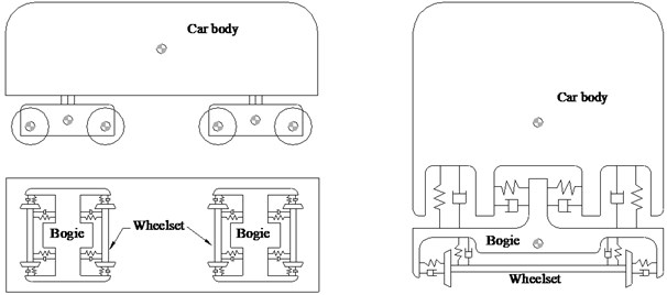
The vehicle model is divided into seven rigid bodies (including one carbody, two bogies and four wheelsets). The rigid bodies are connected by springs and dampers [17-19]. The stiffness and damping of the suspension systems are defined linear or non-linear according to practical situations. The whole vehicle has 34 degrees of freedom, as shown in Fig. 3. The CRH2 (China Railway High-speed) train with eight cars (T+M+M+T+T+M+M+T; M: motor car, T: trailor car) were applied in the analyses. The track irregularities were simulated by German low-disturbance rail spectrum.
Fig. 3Schematic model of a train
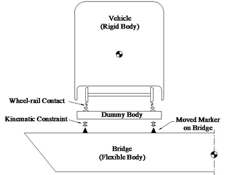
Based on the rigid-flexible coupling method, the vehicle-bridge system modeling method makes full use of the high modeling efficiency of finite element software and the powerful wheel-rail analysis of multi-body system dynamics software [20-21]. The whole rigid-flexible coupling system includes flexible body system (bridge structure) and rigid body system (vehicle), and the two systems are coupled by the dummy bodies, shown in Fig. 4. Dummy body has small mass and mass moment of inertia, to ensure that its impact on the whole system is negligible. The whole system is regarded as a whole coupled system, which is solved by the equation of motion.
Fig. 4Schematic of vehicle-bridge system
As for the bridge structure, it exists as a flexible body in the system. The equations of motion of a flexible body were presented [22]. The position of an arbitrary point on the flexible body can be formulated as:
where is a rotation matrix used for the coordinate transformation from body reference system to the inertial system ; is the position of the body reference system and is the position of point in the undeformed state in the body reference system ; is the flexible body deformation vector.
The Ritz approximation of the deformations of the flexible body is used with a linear combination of shape function with the modal coordinate :
Combining the Ritz-approximation with Hamilton’s principle and using the variational calculus, the equations of motion are formulated [23]:
where is the mass matrix; is the matrix of generalized forces due to gyroscopic and centrifugal terms; and are the matrices of internal and external generalized forces, respectively; , and are time-dependent vectors, which represent absolute acceleration, angular velocity and modal coordinate, respectively.
5. Stress analysis of rigid hanger
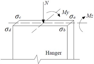
When the train passes through the bridge, the bridge would deform in space, the force of the hanger would change, and the stress would change as well. In the analysis, the longitudinal direction along the bridge is defined as -axis, the transverse direction of the bridge is -axis and the vertical direction is -axis. The section stress consists of three parts: the stress caused by the axial force , the stress by the bending moment around the -axis, and the stress by the bending moment around the -axis. At the certain time, the stress caused by the axial force is the same at every position of the cross section, but the stress caused by the bending moment is different at different positions, shown in Fig. 5. As for the rectangular section, the stress at each corner is the most typical due to the action of and , Hence, the stresses at the four corners of the section were analyzed. Therefore, the stress at each corner of the cross section can be calculated by Eq. (4):
where, is the area of cross-section; is the elastic section modulus around axis; is the elastic section modulus around axis. For circular section, , and is the diameter; for rectangular section, and are or , respectively, and represents the length of the long side, represents the length of the short side.
Fig. 5Stress at each corner of the hanger
Since the axial force and moment of the hanger vary with time when the train passes through the bridge, the stress in Eq. (4) changes with time as well. The stress amplitude of the hanger is the difference between the maximum stress and the minimum stress when the train passes through the bridge. The stress amplitude at the four positions of the section can be expressed as follows:
where, represents different position of the cross-section, .
The maximum stress amplitude can be expressed as:
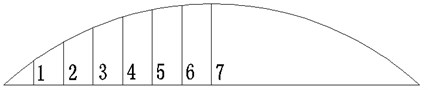
For the convenience of the latter, the hangers on the investigated bridge are defined as number from 1 to 7 from short to long, as shown in Fig. 6. In the study, the vehicle speed was 150 km/h.
Fig. 6Scheme of hanger number
5.1. Circular steel rigid hanger
As there are two sides for hangers on the bridge, which is near and far from the train moving line, the stress amplitudes of hangers on the two sides were compared in Table 3. It can be found that the stress amplitudes of the hangers on the near side are larger than those on the far side, for the hanger on the near side is much more affected by the dynamic actions of the vehicle loads. And the time histories of stresses of the No. 4 hanger on the near side were shown in Fig. 7. Hence, the following results are the stress amplitudes of the hangers on the near side.
Table 3Stress amplitude for hangers on the two sides Δσmax (Unit: MPa)
– | Hanger number | |||||||
1 | 2 | 3 | 4 | 5 | 6 | 7 | ||
Location of hanger | Far side | 8.86 | 6.61 | 5.68 | 10.82 | 8.21 | 5.81 | 6.54 |
Near side | 9.81 | 9.48 | 8.33 | 13.03 | 11.00 | 8.00 | 8.77 | |
The hanger diameter includes 8 sizes, which is from 0.10 m to 0.30 m (Cases B1 to B8). The maximum stress amplitudes of hangers with different diameters were listed in Table 4. It can be seen from the table that the maximum stress amplitude of the hanger decreases with the increase of the diameter. When the diameter of the hanger was 0.3 m (Case B8), the maximum stress amplitude of the hanger was 7.17 MPa. For the hanger diameter of 0.1 m (Case B1), the maximum stress amplitude was 31.97 MPa.
Fig. 7Time histories of stress of the No. 4 hanger on the near side
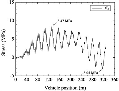
a)
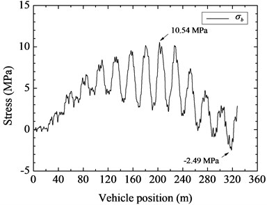
b)
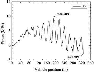
c)
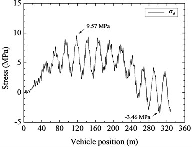
d)
Table 4Stress amplitude by train loads for circular steel solid hanger of different diameters Δσmax (Unit: MPa)
Case | Diameter (m) | Hanger number | ||||||
1 | 2 | 3 | 4 | 5 | 6 | 7 | ||
B1 | 0.10 | 20.75 | 18.99 | 31.97 | 18.34 | 16.94 | 17.40 | 17.16 |
B2 | 0.12 | 10.76 | 12.28 | 15.69 | 14.92 | 15.51 | 12.18 | 12.18 |
B3 | 0.14 | 8.66 | 10.21 | 11.22 | 27.38 | 11.18 | 11.10 | 10.71 |
B4 | 0.16 | 9.77 | 9.48 | 8.33 | 13.03 | 10.64 | 8.24 | 8.77 |
B5 | 0.18 | 8.19 | 7.63 | 9.70 | 8.79 | 23.10 | 9.14 | 7.96 |
B6 | 0.20 | 7.48 | 8.03 | 7.42 | 7.93 | 10.14 | 20.84 | 18.95 |
B7 | 0.25 | 5.77 | 6.02 | 5.98 | 7.61 | 6.34 | 7.09 | 7.00 |
B8 | 0.30 | 5.92 | 5.73 | 5.95 | 6.06 | 5.80 | 6.22 | 7.17 |
5.2. Flat-plate hanger
The flat-plate hanger size consists of three combinations of long side widths ( 0.30 m, 0.45 m and 0.60 m) and three height-width ratios (1:8, 1:6 and 1:4). There are 9 rectangular sections (Cases C1 to C9) in total. From the simulation, the maximum stress amplitudes of flat-plate hanger were listed in Table 5. It can be seen that the maximum stress amplitude decreases with the increase of the short side width , for the same long side width . And for the same and with the increase of , the maximum stress amplitude of the shorter hanger (the length less than 16.406 m) decreases, and the maximum stress amplitude of the longer hanger (the length greater than 22.107 m) increases. When the size of hanger was too small or too large, the maximum stress amplitude of flat-plate hanger was comparatively large.
Table 5Stress amplitude by train loads for flat-plate hanger of different sizes Δσmax (Unit: MPa)
Case | Width (m) | Height (m) | Area (m2) | Height-width ratio | Hanger number | ||||||
1 | 2 | 3 | 4 | 5 | 6 | 7 | |||||
C1 | 0.30 | 0.0375 | 0.011 | 1:8 | 10.05 | 12.16 | 11.92 | 12.79 | 13.83 | 12.53 | 13.03 |
C2 | 0.30 | 0.050 | 0.015 | 1:6 | 9.05 | 10.36 | 9.48 | 10.51 | 10.38 | 9.97 | 10.10 |
C3 | 0.30 | 0.075 | 0.023 | 1:4 | 7.00 | 7.34 | 7.30 | 8.12 | 7.89 | 8.06 | 8.02 |
C4 | 0.45 | 0.05625 | 0.025 | 1:8 | 8.04 | 8.49 | 8.19 | 8.28 | 8.72 | 9.10 | 9.22 |
C5 | 0.45 | 0.075 | 0.034 | 1:6 | 6.38 | 7.13 | 6.37 | 7.42 | 7.93 | 8.32 | 8.50 |
C6 | 0.45 | 0.1125 | 0.051 | 1:4 | 6.29 | 5.92 | 5.99 | 6.89 | 7.45 | 7.84 | 7.86 |
C7 | 0.60 | 0.075 | 0.045 | 1:8 | 6.32 | 6.01 | 6.92 | 8.03 | 9.61 | 10.19 | 10.28 |
C8 | 0.60 | 0.100 | 0.060 | 1:6 | 6.06 | 5.54 | 8.02 | 7.50 | 9.10 | 9.51 | 10.17 |
C9 | 0.60 | 0.150 | 0.090 | 1:4 | 7.54 | 5.67 | 6.70 | 8.00 | 8.92 | 8.76 | 9.30 |
6. Conclusions
The influence of different rigid hangers on the dynamic characteristics of arch bridges was compared and the stress amplitudes of bridge hangers when trains pass through bridges were analyzed. The following conclusions are drawn.
1) When the flexible hanger of arch bridge was replaced by the rigid hanger, the symmetrical vertical bending frequency of arch bridge is significantly increased, the vertical bending frequency of arch bridge corresponding to circular steel hanger and flat-plate hanger increases from 1.4382 Hz to 2.1 Hz and 2.2 Hz, respectively, which increases by nearly 40 % and 45 %.
2) The change of diameter of circular steel hanger has great influences on vertical bending and torsion, but the frequency change rates are less than 5 %. With the increase of hanger diameter, the frequency of first-order transverse bending, first-order asymmetric vertical bending and first-order torsion decreases, while the first-order symmetric vertical bending increases.
3) The change of the size of flat-plate hanger has great influences on the torsion frequency, but the frequency change rate is only 5.6 %. With the increase of the size of flat-plate hanger, the transverse bending frequency decreases and the symmetry vertical bending frequency increases, and the torsional mode of the bridge is doped with the local vibration of the hanger.
4) With the increase of hanger diameter, the maximum stress amplitude of circular steel hanger decreases as a whole.
5) For flat-plate hanger, when the long side size is the same, the maximum stress amplitude of the hanger decreases with the increase of the short side size . When the short side size is the same, with the increase of the long side size , the maximum stress amplitude of the shorter hanger decreases, and the maximum stress amplitude of the longer hanger increases. When the size of the flat-plate hanger is too small or too large, the maximum stress amplitude is large.
The following aspects will be further studied. The next step is to study the vortex-induced vibration of the rigid hanger due to the wind actions, for the wind is one of the commonly encountered circumstances in the practical engineering and the frequency and damping ratio of the steel hanger are comparatively low. Moreover, the stresses of the hanger subjected to vehicle and wind loads at the same time can be studied.
References
-
Fujino Y., Siringoringo D. Vibration mechanisms and controls of long-span bridges: a review. Structural Engineering International, Vol. 23, Issue 3, 2013, p. 248-268.
-
Wu W. Q., Wang H., Zhu Y. J., Yu J. Y., Zhao H., Zhang H. New hanger design approach of tied-arch bridge to enhance its robustness. KSCE Journal of Civil Engineering, Vol. 22, Issue 5, 2018, p. 4547-4554.
-
Chudzikiewicz A., Bogacz R., Kostrzewski M., Konowrocki R. Condition monitoring of railway track systems by using acceleration signals on wheelset axle-boxes. Transport, Vol. 33, Issue 2, 2018, p. 555-566.
-
Li Y. L., Xiang H. Y., Wang B., Xu Y. L., Qiang S. Z. Dynamic analysis of wind-vehicle-bridge coupling system during the meeting of two trains. Advances in Structural Engineering, Vol. 16, Issue 10, 2013, p. 1663-1670.
-
Yoshimura M., Wu Q. X., Takahashi K., Nakamura S., Furukawa K. Vibration analysis of the Second Saikai Bridge – a concrete filled tubular (CFT) arch bridge. Journal of Sound and Vibration, Vol. 290, Issues 1-2, 2006, p. 388-409.
-
Leander J., Andersson A., Karoumi R. Monitoring and enhanced fatigue evaluation of a steel railway bridge. Engineering Structures, Vol. 32, Issue 3, 2010, p. 854-863.
-
Banjara N. K., Sasmal S. Remaining fatigue life of steel railway bridges under enhanced axle loads. Structure and Infrastructure Engineering, Vol. 10, Issue 2, 2014, p. 213-224.
-
Malveiro J., Sousa C., Ribeiro D., Calçada R. Impact of track irregularities and damping on the fatigue damage of a railway bridge deck slab. Structure and Infrastructure Engineering, Vol. 14, Issue 9, 2018, p. 1257-1268.
-
Bogacz R., Czyczula W., Konowrocki R. Influence of sleepers shape and configuration on track-train dynamics. Shock and Vibration, Vol. 2014, 2014, p. 393867.
-
Cantero D., Karoumi R. Numerical evaluation of the mid-span assumption in the calculation of total load effects in railway bridges. Engineering Structures, Vol. 107, 2016, p. 1-8.
-
Moliner E., Martínez Rodrigo M.-D., Museros P. Dynamic performance of existing double track railway bridges at resonance with the increase of the operational line speed. Engineering Structures, Vol. 132, 2017, p. 98-109.
-
Hu N., Dai G. L., Yan B., Liu K. Recent development of design and construction of medium and long span high-speed railway bridges in China. Engineering Structures, Vol. 74, 2014, p. 233-241.
-
Zhao H. W., Ding Y. L., An Y. H., Li A. Q. Transverse dynamic mechanical behavior of hangers in the rigid tied-arch bridge under train loads. Journal of Performance of Constructed Facilities, Vol. 31, Issue 1, 2017, p. 04016072.
-
Chen Z. Q., Liu M. G., Hua X. G., Mou T. M. Flutter, galloping, and vortex-induced vibrations of H-section hangers. Journal of Bridge Engineering, Vol. 17, Issue 3, 2012, p. 500-508.
-
Ribeiro D., Calçada R., Delgado R., Brehm M., Zabel V. Finite element model updating of a bowstring-arch railway bridge based on experimental modal parameters. Engineering Structures, Vol. 40, 2012, p. 413-435.
-
Klinger C., Michael T., Bettge D. Fatigue cracks in railway bridge hangers due to wind induced vibrations – failure analysis, measures and remaining service life estimation. Engineering Failure Analysis, Vol. 43, 2014, p. 232-252.
-
Zhai W. M., Han Z. L., Chen Z. W., Ling L., Zhu S. Y. Train-track-bridge dynamic interaction: a state-of the-art review. Vehicle System Dynamics, Vol. 57, Issue 7, 2019, p. 984-1027.
-
Arvidsson T., Karoumi R. Train-bridge interaction – a review and discussion of key model parameters. International Journal of Rail Transportation, Vol. 2, 2014, p. 147-186.
-
Melnik R., Kostrzewski M. Rail vehicle’s suspension monitoring system - analysis of results obtained in tests of the prototype. Key Engineering Materials, Vol. 518, 2012, p. 281-288.
-
Xu X. Y., Li Y. L. Dynamic analysis of wind-vehicle-bridge system based on rigid-flexible coupling method. World Congress on Advances in Civil, Environmental and Materials Research (ACEM16) Jeju Island, Korea, 2016.
-
Li Y. L., Xu X. Y., Zhou Y., Cai C. S., Qin J. X. An interactive method for the analysis of the simulation of vehicle–bridge coupling vibration using ANSYS and SIMPACK. Proceedings of the Institution of Mechanical Engineers, Part F: Journal of Rail and Rapid Transit, Vol. 232, Issue 3, 2018, p. 663-679.
-
Dietz S., Hippmann G., Schupp G. Interaction of vehicles and flexible tracks by co-simulation of multibody vehicle systems and finite element track models. Vehicle System Dynamics, Vol. 37, Issue 1, 2002, p. 372-384.
-
Wallrapp O. Standardization of flexible body modeling in multibody system codes, Part I: definition of standard input data. Mechanics of Structures and Machines, Vol. 22, Issue 3, 1994, p. 283-304.
About this article

