Abstract
Nowadays, using high-ductility structures in the construction and use of significant buildings is highly appreciated. To use more ductile structures, effort has been made in this research to introduce box-plate beam-to-column connections. They underwent hysteretic loading and it was found from their moment-rotation curves that the bending capacity and ductility of the box-plate connection were more than ordinary rigid connection, and those of the latter were more than those of the normal typical one. It was also shown that stress concentration in box-plate connections disappears over the top and bottom flange plates.
1. Introduction
Before North Ridge Earthquake in 1994, structures that had lateral resisting systems with rigid frames were considered as the most ductile and most earthquake resisting compared with other similar systems, but the “Earthquake” resulted in much damage in steel rigid structures that had welded beam-to-column connections. Numerous studies were done and showed that the reasons for the damage were different brittle fractures in the welded connections; such fractures prevent the connections’ inelastic behavior and hence reduce the structure ductility [1].
Chen et al. (2003) studied the longitudinal toothed connection and its bending capacity through laboratory tests and simulation methods and showed that it prevented brittle fractures (in the beam penetration part) and reduced stress concentration at the connection end and hence prevented the flange failure. They showed in their study that local stress concentration was reduced, plastic hinge was formed at a good distance from the column, the system showed appropriate ductility (without any brittle fractures) [2].
Tehranizadeh et al. (2012) studied the effects of the upper and lower plates on the bending rigidity of the restrained joints using three real-size beam-to-column connections all tested under hysteretic loading. The results, validated through simulations in the ABAQUS Software, revealed that the deformations were nearly similar in all three models. Accordingly, they suggested that it would be beneficial if the flange plates had the shortest lengths, welding materials were high-strength (resistant), and the upper and lower plates’ thicknesses for welding were the highest allowable [3].
In the present research, one novel rigid connection is introduced and compared, for their ductility and moment capacity, with typical restrained connections through their related moment-rotation diagrams drawn under similar regular dimensions, loading, and boundary conditions. [4, 5].
2. Methodology
In this research, the typical and novel connections have been studied by the FEM under ultimate and hysteretic loading and their performances have been compared through their moment-rotation diagrams. This research uses weld and beam-to-column sections and relates them together with ties and friction interaction to do modeling in the ABAQUS by virtue of the papers validated by laboratory methods and the mentioned software [5, 6, 7, and 8].
For a better study of the finite element model and the modeling verification, first the beam-to-column connection investigated by Tehranizadeh et al. was modeled in the ABAQUS and then its finite element analyses results were compared with those of the laboratory tests. In short, the dimensions of the beam-column plates, connections, welds and specifications of the plates (Table 1), were used in the ABAQUS finite element software as inputs. The simulation models of the ordinary typical and box-plate connections are shown in Figs. 1 and 2 respectively [7].
Table 1Dimensions of the plates used in the FE modeling and specifications of the plates used in the finite element model [3]
Plate | Length | Width | Thickness | Yield point | Ultimate point | ||
Strain (%) | Stress (MPa) | Strain (%) | Stress (MPa) | ||||
Beam flange | 2500 | 200 | 12 | 0.15 | 300 | 18 | 430 |
Beam web | 2500 | 380 | 8 | 0.155 | 310 | 17 | 400 |
Column | 3000 | 400 | 20 | 0.145 | 290 | 15 | 390 |
Upper | 150 | 50 | 15 | 0.155 | 310 | 18 | 450 |
Lower | 150 | 80 | 10 | 0.145 | 290 | 15 | 390 |
Col. Continuity | 380 | 380 | 10 | 0.145 | 290 | 15 | 390 |
Box-plate num1 | 2500 | 300 | 8 | 0.145 | 290 | 15 | 390 |
Box-plate num2 | 2500 | 300 | 10 | 0.145 | 290 | 15 | 390 |
Box-plate num3 | 2500 | 300 | 15 | 0.145 | 290 | 15 | 390 |
Box-plate num4 | 2500 | 300 | 20 | 0.145 | 290 | 15 | 390 |
Weld material | 0.26 | 525 | 12 | 560 | |||
Fig. 1Simulation of an ordinary typical connection and boundary conditions in the ABAQUS Software [7]
![Simulation of an ordinary typical connection and boundary conditions in the ABAQUS Software [7]](https://static-01.extrica.com/articles/18548/18548-img1.jpg)
Fig. 2Simulation of the box-plate connection in the ABAQUS Software [7]
![Simulation of the box-plate connection in the ABAQUS Software [7]](https://static-01.extrica.com/articles/18548/18548-img2.jpg)
3. Findings
Fig. 3 shows Three different typical curves of Moment-rotation for fully restrained (FR), partially restrained (PR) and simple (S) connections.
Fig. 3Three different typical curves of moment-rotation for fully restrained (FR), partially restrained (PR) and simple (S) connections [9, 10]
![Three different typical curves of moment-rotation for fully restrained (FR), partially restrained (PR) and simple (S) connections [9, 10]](https://static-01.extrica.com/articles/18548/18548-img3.jpg)
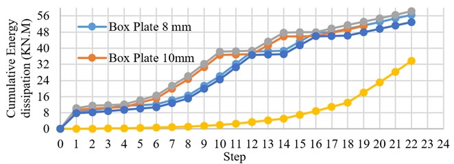
Fig. 4 shows Protocol load in this research. Fig. 5 shows their moment-rotation diagrams and Fig. 8 shows pushover curves and the bending capacity of model. Fig. 10 shows energy dissipation of the ordinary and four box-plate connections under the application of 22 similar loading cycles (of the displacement type), and. Also, connections with no brittle failure have rotated more than 4 radians. It is clears that Tangent of graph shows stiffness for models [7, 9-11].
Fig. 4Displacement-time analyses of all the models [7]
![Displacement-time analyses of all the models [7]](https://static-01.extrica.com/articles/18548/18548-img4.jpg)
Fig. 5Moment-rotation curves of five models under 22 loading cycles [7]
![Moment-rotation curves of five models under 22 loading cycles [7]](https://static-01.extrica.com/articles/18548/18548-img5.jpg)
Fig. 6 shows the stress at the end of the 22nd loading cycle in the ordinary and box-plate models respectively [7].
Fig. 7 shows the plastic strain in the 22nd loading cycle in the ordinary and box-plate connections respectively. In the first model (ordinary), the plastic strain at the junction of the upper and lower plates is 43.33 and 6.6 times those in the third models respectively [7].
Fig. 6Triaxial stress in five models: a) ordinary model, b) box plate connection thickness = 20 mm [7]
![Triaxial stress in five models: a) ordinary model, b) box plate connection thickness = 20 mm [7]](https://static-01.extrica.com/articles/18548/18548-img6.jpg)
a)
![Triaxial stress in five models: a) ordinary model, b) box plate connection thickness = 20 mm [7]](https://static-01.extrica.com/articles/18548/18548-img7.jpg)
b)
Fig. 7Plastic strain in five models: a) ordinary model, b) box plate connection thickness = 20 mm [7]
![Plastic strain in five models: a) ordinary model, b) box plate connection thickness = 20 mm [7]](https://static-01.extrica.com/articles/18548/18548-img8.jpg)
a)
![Plastic strain in five models: a) ordinary model, b) box plate connection thickness = 20 mm [7]](https://static-01.extrica.com/articles/18548/18548-img9.jpg)
b)
Fig. 8 shows pushover curves of five models under 22 loading cycles. The integral of this graph is cumulative energy dissipation. It is clears that Tangent of graph pushover curve is stiffness for model. Fig. 9 shows limits of stiffness for simple connection and rigid connection. Energy Dissipations for models is calculated as integral of graph Fig. 8. The results this calculation shows in Fig. 10. [7, 9 and 10]
Fig. 8Pushover curves of five models under 22 loading cycles
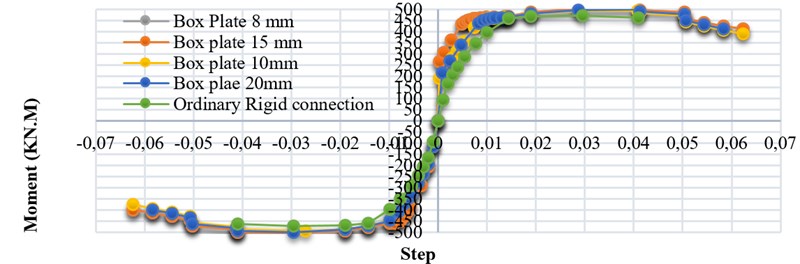
Fig. 9Two different typical curves of moment-rotation for fully restrained (FR), partially restrained (PR) and simple (S) connections [9, 10]
![Two different typical curves of moment-rotation for fully restrained (FR), partially restrained (PR) and simple (S) connections [9, 10]](https://static-01.extrica.com/articles/18548/18548-img11.jpg)
Fig. 10Cumulative energy dissipation of five models under 22 loading cycles
4. Conclusions
The modeling of the ordinary and box-plate connections under hysteretic loading showed that:
1) They all rotated more than 4 radians in the 22nd loading cycle meaning that according to the AISC Seismic Code they can be used in the Special Moment Frame systems.
2) The bending moment capacity of the box-plate model is 10.6 % more than that of the Ordinary model.
3) Energy dissipation in the box-plate model is 65 % more than that in the ordinary model.
4) In the box-plate model, the stress concentration in the upper and lower plates is less than those of the ordinary model and its value at the web center is 1.35 times that in the upper and lower plates.
5) Tangent Box plate connection shows that this model is semi-rigid connection.
References
-
Mirghaderi S. R., Dehghani R. Continuous beam-to-column rigid seismic connection. Journal of Constructional Steel Research, 2008, p. 1516-1529.
-
Chen Cheng-Chi, Lee Jen-Ming, Lin Ming-Chi Behavior of Steel Moment Connections with a Single Flange Rib. Department of Civil Engineering, National Chiao Tung University, Taiwan, 2003, p. 1419-1428.
-
Gholami M., Deylami A., Tehranizadeh M. Seismic performance of flange plate connections between steel beams and box columns. Journal of Constructional Steel Research, 2012, p. 38-48.
-
Wang Wei, Zhang Yanyan, Chen Yiyi, Lu Zhihao Enhancement of ductility of steel moment connections with non-compact beam web. Journal of Constructional Steel Research, 2012, p. 114-123.
-
Azhari M., Mirghaderi R. Design of Steel Structures. Based on the AISC Code, First Editing, Vol. 1, 2005.
-
Azhari M., Mirghaderi R. Design of Steel Structures. Based on the AISC Code, First Editing, Vol. 3, 2005.
-
ABAQUS Ver13.4.
-
Kaufmann E. J. Dynamic Tension Tests of Simulated Moment Resisting Frame Weld Joints, Steel Tips, Structural Steel Education Council, AISC, Chicago, 1997.
-
Specification for Structural Steel Buildings. AISC 360, American Institute of Steel Construction, Chicago, Illinois, 2005.
-
State of the Art Repot on Connection Performance. Prepared by the SAC Joint Venture for the Federal Emergency Management Agency, FEMA-355D, Washington, DC, 2000.
-
ABAQUS Theory Manual. Version 6.3, Hibbitt Karlson and Sorensen, Inc., 2002.
Cited by
About this article

