Abstract
To improve dynamic characteristics of synchronous magnetic coupling, this paper mainly analyzed the influence of the installation deviation on the synchronous magnetic coupling’s dynamic performance used in the horizontal axis wave energy power generation device. Dynamic characteristics equations based on Lagrange equation are built in the paper to analyze the dynamic characteristic of synchronous magnetic coupling. The radial deviation, the angle deviation and the center-of-mass deviation are considered in the equation. The influence of those installation deviations on the synchronous magnetic coupling performance is analyzed based on the mathematical model. The results show that the rise time, the overshoot, the peak time, the adjusting time and the oscillation of the synchronous magnetic coupling are almost not affected by those installation deviations.
1. Introduction
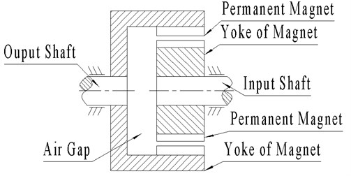
Synchronous magnetic coupling has many characteristics, including isolated transmission, flexible transmission, overload protection, as shown in Fig. 1. It is widely applied to places require to be completely sealed or isolated from the vibration of the input. Sometimes it is used to avoid overloading [1-3]. It can be used in many devices, such as wave energy device, wind equipment [4]. In addition to these advantages, the synchronous magnetic coupling has a low request for the installation precision and it is convenient to fix and use.
Fig. 1Synchronous magnetic coupling
The horizontal axis wave energy power generation device is the floating type wave energy device. It works in bad sea condition. It is very hard to maintain. So, the device requires high reliability. For the marine equipment, one of the most common problems is seawater infiltration. The equipment will suffer great destruction that can make the equipment lose working ability and scrapped. During two sea trials, the horizontal axis wave energy power generation device suffered seawater infiltration in different degrees. Analysis found that the location at the connective part between the water turbine and the coupling was radial contact seal. The radial contact seal failed. Seawater entered into the device continuously. And as time went on, seawater accumulated and the device finally lost working ability. By searching papers, magnetic drive mechanism used in the chemical pump was introduced into the horizontal axis wave energy power generation device. It can achieve zero leakage of the seal unit at the transmission part and improve the device reliability.
This paper mainly analyzed the influence of the installation deviation on synchronous magnetic coupling performance used in the horizontal axis wave energy power generation device. The device captured wave energy and then converted it into turbine rotational mechanical energy. The speeder accelerated the turbine and drove the generator. The compartment setting speeder needs to be isolated from the seawater and is protected from seawater infiltration. The sealing reliability requirement is very high. So, the synchronous magnetic coupling is used as torque transmission mechanism.
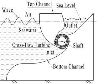
It was difficult to ensure coaxiality between the speeder and the water turbine because the horizontal axis wave energy power generation device size is 6 m×6 m×6 m, which is large. The water turbine’s diameter is 1.5 m, and its length is 4 m. Fig. 2 is the prototype device. Fig. 3 is the device schematic diagram. The traditional transmission mechanism often uses rigid connection. There is a big prestressing force after installation if there is the installation error. That creates the pulsating stress in the transmission part when the device works. It accelerates the failure of the device. The synchronous magnetic coupling can solve a series of problems caused by the installation error at the transmission position. And it allows the position deviation. In order to analyze the influence of the installation deviation on synchronous magnetic driver performance, the research is carried out.
Fig. 2Prototype device
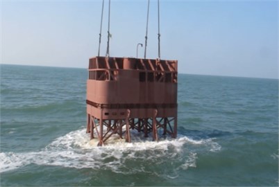
Fig. 3Device schematic diagram
2. Mathematical model
The synchronous magnetic coupling performance is influenced by magnet parameters, air-gap, load [5]. There’s installation deviations when the synchronous magnetic coupling is installed. The installation error may be axial, radial or angle direction, as shown in Fig. 4. In order to analyze the influence of the installation deviation on synchronous magnetic coupling performance, the driven rotor installation deviations are analyzed.
Lagrange equation is usually used to build dynamic equations of mechanism [6-8], it can analyze the dynamic characteristics by defining generalized force and generalized coordinates. The dynamic equations deduced from Lagrange equation can avoid constraint reaction and reduce solving difficulty.
The Lagrange equation is written as:
where is generalized coordinates; is generalized velocity; is kinetic energy; is potential energy; is generalized force.
Fig. 4Installation deviation
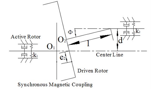
According to geometric relations and Fig. 4, The kinetic energy is:
where is the mass of the active rotor; is the mass of the driven rotor; is translational velocity of the active rotor; is the translational velocity of the driven rotor; is the rotational inertia of the active rotor; is the rotational inertia of the driven rotor; is the center-of-mass deviation of the active rotor; is the center-of-mass deviation of the driven rotor; is the rotation angle of the active rotor; is the rotation angle of the driven rotor.
The potential energy is:
where is the elastic stiffness of input; is the elastic stiffness of output; is angular difference between the active and driven rotors; is the torsional rigidity; (, ) are the geometric center coordinates of the driven rotor; (, ) are the geometric center coordinates of the active rotor.
The input torque and damping force are applied on the active rotor, as the damping force are applied on the driven rotor. Those torques and forces are non-potential generalized force, so:
According to Eqs. (1-4), dynamic equations of synchronous magnetic coupling can be expressed as:
Because the geometric center coordinates is fixed, dynamic equations can be simplified as follows:
The transfer function between and is got from Eq. (6):
3. Dynamic characteristics analysis
According to the measurement and calculation, 0.17 Kg·m2, 1.37 Nm·s/rad, 45 Nm/rad, 6.5 Kg, 0.1 m. Then the influence of the center-of-mass deviation , radial deviation and angle deviation on the dynamic charactieare is analyzed.
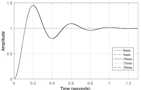
According to physical measurement, the diameter of the driven rotor is 160 mm, so is set as 0, 5, 10, 15, 20 mm to analyze the unit step dynamic response characteristic of the synchronous magnetic coupling. The Dynamic Response Curve of is obtained, as shown in Fig. 5. From Fig. 5, rise time, peak time and accommodation time are almost unchanged with the increase of the center-of-mass deviation . The maximum overshoot and oscillation times keep unchange with various center-of-mass deviation . So, the center-of-mass deviation has little influence on the dynamic characteristic of the synchronous magnetic coupling.
Fig. 5Dynamic response curve of e2
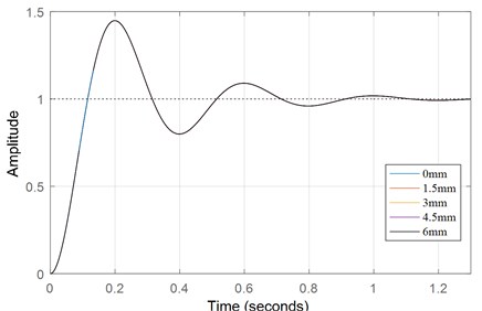
The air gap between the driven rotor and the active rotor is 6 mm, so is set as 0, 1.5, 3, 4.5, 6 mm to analyze the unit step dynamic response characteristic of the synchronous magnetic coupling. The Dynamic Response Curve of is obtained, as shown in Fig. 6. According to Fig. 6, radial deviation has almost no effect on dynamic characteristic like the center-of-mass deviation .
Fig. 6Dynamic response curve of d
The length of the driven rotor is 50 mm, and the air gap is 6 mm, so is set as 0, 0.03, 0.06, 0.09, 0.12 rad to analyze the unit step dynamic response characteristic of the synchronous magnetic coupling. The Dynamic Response Curve of is obtained, as shown in Fig. 7. The angle deviation has almost no effect on dynamic characteristic like the radial deviation and the center-of-mass deviation .
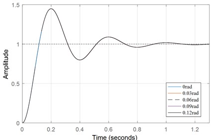
Fig. 7. Dynamic response curve of
According to the above analysis, the center-of-mass deviation , radial deviation and angle deviation have almost no effect on the dynamic characteristics of the synchronous magnetic coupling. When the installation deviations exist, the synchronous magnetic coupling can work as no installation deviations. That means the synchronous magnetic coupling is a flexible transmission mechanism and allows the installation deviations exists in the horizontal axis wave energy power generation device.
4. Conclusions
According to the analysis mentioned above, the dynamic characteristics of the synchronous magnetic coupling is almost not effected by the installation deviations, including the center-of-mass deviation , radial deviation and angle deviation . The analysis results show that the synchronous magnetic coupling is a flexible transmission mechanism and can improve the dynamic characteristics with the installation deviations. The synchronous magnetic coupling can be used in the wave energy power generation device to improve the device reliability and practicality and avoid the influence of installation deviations on the device performance.
References
-
Mei S. Research progresses of design methods for axial magnetic coupling drive mechanisms. Zhongguo Jixie Gongcheng/China Mechanical Engineering, Vol. 22, Issue 19, 2011, p. 2375-2381.
-
Uno M. Development of the floating centrifugal pump by use of non contact magnetic drive and its performance. International Journal of Rotating Machinery, Vol. 10, Issue 5, 2004, p. 337-344.
-
Astariz S., Iglesias G. The economics of wave energy: a review. Renewable and Sustainable Energy Reviews, Vol. 45, 2015, p. 397-408.
-
Potgieter J. H. J., Kamper M. J. Optimum design and comparison of slip permanent-magnet couplings with wind energy as case study application. IEEE Transactions on Industry Applications, Vol. 50, Issue 5, 2014, p. 3223-3234.
-
Wang Y.-L. A wave energy converter with magnetic gear. Ocean Engineering, Vol. 101, 2015, p. 101-108.
-
Lazaroff-Puck C. Gearing up for Lagrangian dynamics. Archive for History of Exact Sciences, Vol. 69, Issue 5, 2015, p. 455-490.
-
Goulos I., Pachidis V., Pilidis P. Lagrangian formulation for the rapid estimation of helicopter rotor blade vibration characteristics. Aeronautical Journal, Vol. 118, Issue 1206, 2014, p. 861-901.
-
Zhong H. Lagrangian dynamic large-eddy simulation of wind turbine near wakes combined with an actuator line method. Applied Energy, Vol. 144, 2015, p. 224-233.
About this article
The research is supported by the Fundamental Research Funds of Shandong University (Project No. 2016JC035) and the Natural Science Foundation of Shandong Province (Project No. ZR2016WH02), which are gratefully acknowledged.
