Abstract
The seismic problem of concrete dams has long been a difficult issue facing academic and engineering researchers. Traditional anti-seismic and isolation measures produce unfavorable results in hydraulic structures. However, the air-cushion seismic isolation technique represents a new development orientation for the anti-seismic method of concrete dams. To study the isolation and anti-cracking effects of the air-cushion, the gas-liquid-solid tri-phase coupling numerical model of the air-cushion isolation control of high arch dams is presented in this paper, in which the cracking behavior of concrete is considered. A 300 m level dam was simulated numerically under three different seismic intensities. The results show that the air-cushion reduces the hydrodynamic pressure significantly. The maximum hydrodynamic pressure is reduced by more than 70 %, and the acceleration of the dam crest is reduced by more than 50 % with a 1 m air-cushion. The reduction in hydrodynamic pressure and dam acceleration increases with increasing seismic intensity. In addition, the air-cushion decreases the cracking range of the dam body effectively. Thus, the isolation effects of the air-cushion are remarkable.
1. Introduction
Western China is currently in a seismic active period and the frequent earthquake activity has brought heavy loss to human life and property; recent earthquakes include Wenchuan M_s8.0, Yushu M_s7.1, and Lushan M_s7.0. China has abundant water resources, predominantly concentrated in western China. In recent years, many high concrete dams have been constructed in this meizoseismal area, including Xiaowan Hydropower Station (arch dam with a height of 294.5 m and design peak acceleration of 0.308 g), Dagangshan Hydropower Station (arch dam with a height of 210 m and design peak acceleration of 0.557 g), Guandi Hydropower Station (concrete gravity dam with a height of 168 m and design acceleration of 0.34 g), and Jin’an Bridge (with a height of 160 m and design acceleration of 0.399 g). Safety is of great concern to all these projects and any accident will have disastrous consequences. For example, an earthquake near Koyna Dam in India will result in cracks on the upstream and downstream surfaces of many non-overflow dam sections, and a degree of seepage.
The conventional seismic control technique of concrete dams adopts anti-quake reinforcement, which has been studied by numerical simulation to verify the anti-seismic effects [1, 2]. Bidirectional reinforcement of Inguri Dam in the former Soviet Union, which has a height of 271 m, reaches as much as 23.9 thousand tons. The cost thereof was significantly high [3]. Some other researchers propose energy dissipation seismic control, deploying springs, dampers [4], and shape memory alloy (SMA) energy dissipation bars [5] in horizontal joints of the arch dam. Since the opening of the horizontal joints of a high arch dam during an earthquake is relatively small (approximately 10 mm), which is smaller than the stroke of a building-bridge damper, the hysteretic energy dissipation is low.
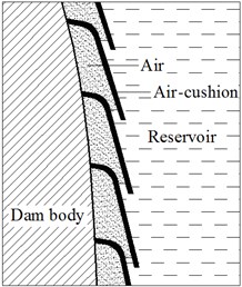
The energy of seismic waves is transmitted to a dam body through two structures: dam base and reservoir. For building and bridge projects, a rubber seismic cushion is placed between the ground and foundation to reduce the earthquake energy transmitted through the ground base [6, 7]. However, it is difficult to use this method for hydro-structures, since dams are of massive weights and the water pressure at the bottom of reservoirs is high. Westergaard [8] proposed that earthquake energy transmitted through water presents as hydrodynamic pressure. For a long time, researchers globally have paid considerable attention to the issue owing to its importance in real projects [9-11]. Air is widely adopted as a seismic isolation and damping material for its high compressibility. In the shipbuilding industry, air-cushions are used to reduce the friction resistance and noise of ships during motion [12-14]; in the transportation industry, air springs are used as effective vibration isolators or absorbers in suspension systems of trains and trucks, effectively controlling the vibration of the parts [15]; an example of an air-cushion application in a hydro-structure is the air-cushion surge tower in hydropower stations. When the water pressure in the pressure pipe rises, water flows into the surge chamber and compresses the air in the chamber. The majority of the energy is dissipated through thermal motion of the air, causing a reduction in pressure. Based on this idea, a layer of air-cushioning is placed between the dam surface and reservoir (Fig. 1) as a soft buffer layer and low pass filter to isolate the transmission of the water wave and reduce the hydrodynamic pressure, thereby further reducing the dynamic response of the dam. This measure is referred as air-cushion seismic control of concrete dams [3, 16]. As early as the 1950s and 60s, the former Soviet Union and France started to study air-cushion seismic isolation technology for dams and achieved success. Haowu et al. [3, 16] proposed a dynamic analysis model of the interactive effect of a dam-dam base-air-cushion-reservoir. In the model, the displacement format of the Lagrangian method is adopted for the air-cushion element; based on the ideal air state equation, the relation between material parameters of the air-cushion element and water pressure is derived. Using the model, a 3-dimensional numerical simulation of air-cushion seismic isolation was carried out for the Jinping first-stage high-arch dam (305 m) and the result proved the seismic isolation effect of the air-cushion. In 2010, Sichuan University finished a large-scale shake table model test of air-cushion seismic isolation of the Jinping first-stage arch dam.
Fig. 1Sketch map of air-cushion isolation
The results fitted well with those of the numerical simulation, further proving the effectiveness of the numerical model and isolation effect of the air-cushion [3]. At present, there are many reports on damage analysis methods and model test researches for concrete dams after strong earthquakes [17-19]. In this paper, the crack activity of dam concrete is considered for the first time in a dam-dam base-air-cushion-reservoir dynamic analysis model; the effect of air-cushion seismic isolation on reducing cracks of concrete dams subjected to strong earthquakes is studied further.
2. Dynamic analysis model
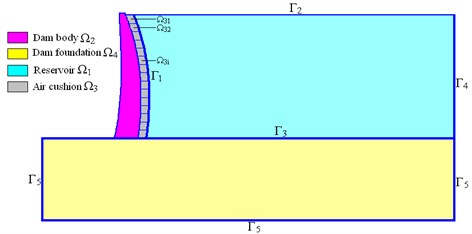
In the dam-dam base-air-cushion reservoir coupling system shown in Fig. 2, the pressure field format of the Euler method is adopted for reservoir , which has pressure freedom; the displacement format of the Lagrangian method is adopted for air-cushion , which has displacement freedom; the dam-dam base satisfies the elasticity equation and the cracking of the dam concrete is considered. The interface of the air-cushion and dam automatically satisfies the displacement compatibility condition; the interface of the air-cushion and reservoir satisfies the mechanical balance condition; the free face of reservoir constrains the pressure freedom; the reservoir tail adopts an infinite boundary; and the boundary of dam base adopts a viscous-spring artificial boundary.
Fig. 2Schematic of the dam body-dam foundation–air-cushion-reservoir dynamic coupling system
2.1. Dynamic balance equation of water
Water is assumed to be: (1) irrotational and inviscid with no heat exchange; (2) slightly compressible; (3) homogenous; (4) slightly deformable with a flow speed significantly slower than the acoustic speed in water. Based on this, the wave equation can be obtained with pressure as the objective function:
where is the acoustic speed in water, is the bulk modulus of water, and is the density of water.
The Galerkin method is adopted to discretize Eq. (1) after introducing proper boundary conditions, by which the dynamic balance equation of water can be obtained as:
where [], [], and [] represent the mass matrix, damping matrix, and rigidity matrix, respectively; [] is the coupling matrix on the interface between the dam and reservoir; the node pressure vector of water; the density of water; and the acceleration vector of the node on the interface of the dam and reservoir.
2.2. Mechanical model of air-cushion
2.2.1. Basic assumption
The following assumptions are made to simplify the question: (1) the air-cushion is uniformly distributed on the upstream face of the dam; (2) the air in the chamber is ideal air, satisfying the ideal air state Eq. (3); (3) since the earthquake duration is short, there is insufficient time for heat exchange and the change of the air state in the chamber is considered to be an isentropic process, i.e., 1.4 in Eq. (3); (4) the flow speed of the air in the chamber is low; and (5) there is no leakage from the air chamber:
In the equation: and represent the pressure and volume of air under state , respectively; and is the polytropic exponent of air.
2.2.2. Constitutive relation of air-cushion
To ensure that the interface of the dam and air-cushion satisfies the displacement compatibility conditions, the displacement format of the Lagrangian method is adopted for the air-cushion element, and its constitutive equation can be represented as:
where is the bulk strain; the bulk modulus; the shear strain; the coefficient ensuring shear stability of the elements, which can be taken as ×10-9; the pressure; and the shear stress.
2.2.3. Material parameters of the air-cushion
The damping effect of the air-cushion can be neglected because the viscous coefficient is relatively small. The bulk modulus and density of the air-cushion element are related to the air state, i.e., the ambient pressure. Therefore, the material parameters of air-cushion elements at different elevations in Fig. 1 differ and are dependent on pressure.
Assume that pressure of air under standard atmospheric pressure is and the density is . The air state under standard atmospheric pressure is set to be the initial state ( 0). Combining Eq. (3), the density and bulk modulus, respectively, of air in a chamber under pressure can be obtained as:
In Fig. 1, under hydrostatic pressure, pressure of air in the chamber is equal to that of water at the same elevation. Therefore, the initial pressures of the different chambers differ. Since the air state under standard atmospheric pressure is considered as the initial state, the initial bulk of air in the chamber will be non-zero. The incremental equation of the air-cushion element can be obtained by converting Eq. (6) to:
where is the pressure increment, i.e., hydrodynamic pressure; the centroid pressure of the air-cushion element, which is equal to sum of standard atmospheric pressure, hydrostatic pressure, and hydrodynamic pressure; the bulk strain increment; and the equivalent bulk modulus of the air-cushion element.
2.3. Crack model of concrete
This study adopts the crack model of concrete in ANSYS software. It is assumed in the model that concrete will only crack along the integration point of the element and there are three orthogonal crack directions for every integration point. According to the stress state of the integration point, the Willam-Warnker five-parameter failure criteria in Eq. (8) is used to judge whether cracking occurs at the point:
In the equation, is function related to the principal stress state; a function of failure face; , , , , and represent uniaxial compressive strength, uniaxial tensile strength, biaxial compressive strength, uniaxial compressive strength under hydrostatic pressure, and biaxial compressive strength under hydrostatic pressure, respectively.
When the first crack occurs at the integration point, the other two possible crack directions are confirmed, and sequential calculation will only judge whether a crack occurs in these two directions. According to crack state of the element (no crack, open, or closed), different constitutive matrixes of the element are selected to simulate concrete crack behavior. When there is no concrete crack, the constitutive matrix is Eq. (9); when concrete cracks along direction of the local coordinate system of a certain integration point, the constitutive matrix of the integration point is Eq. (10); when the crack is closed, the constitutive matrix is Eq. (11). Constitutive matrixes of other crack states can be obtained using the same principle:
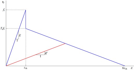
In the equation, is the elasticity modulus; Poisson’s ratio; and the shear stress transmission coefficient when the crack is open, and closed, respectively, and these satisfy 1 0; the elasticity modulus after cracking, which changes with crack strain and is definition in Fig. 3; the tensile stress relaxation coefficient; and the crack strain:
Fig. 3Uniaxial tension stress-strain relationship of concrete
3. Verification experiment
To verify the seismic isolation effect of the air-cushion and correctness of the numerical model, a 6×6 m large-scale high-performance earthquake simulation shaking table from the Nuclear Power Institute of China (made by Servo Test Co., Britain) was used to conduct a 1:300 dynamic model test for Jinping I Arch dam [3, 16], as shown in Fig. 4. Taking El Centro seismic wave and Wenchuan-Shifang seismic wave as the power input, the vibration test considered different peak accelerations under working conditions with and without an air-cushion.
Fig. 4Shaking table test
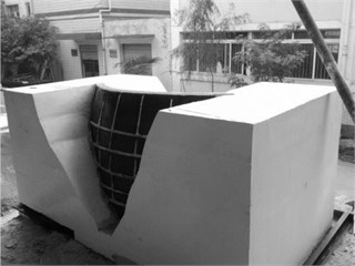
a) Organic glass supporting structure on the upstream face of dam
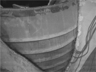
b) Air chamber and air tube
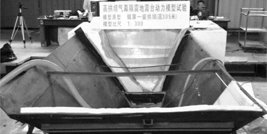
c) Experimental model
A comparison between the test results and numerical simulation results of the vibration caused by the Wenchuan-Shifang seismic wave with a peak acceleration of 0.55 g is shown in Fig. 5 and Table 1. These show that the air-cushion significantly reduces the hydrodynamic pressure. Meanwhile, the acceleration response also decreases. The calculation value and measuring value of the reduction in hydrodynamic pressure on the dam bottom are 82.6 % and 76.9 %, respectively. In the calculation model, the air-cushion is distributed fully; however, in the test model, the distribution area of the air-cushion is reduced owing to the existence of the supporting structure (as shown in Fig. 4(a)). Therefore, the calculation results of the hydrodynamic pressure reduction are higher than the measuring results. After using the air-cushion, the associated mass of dam decreases owing to the reduction in hydrodynamic pressure, leading to an increase in natural frequency. Generally, the test results fit well with the calculation results, verifying the seismic isolation effect of the air-cushion and correctness of the numerical model.
Fig. 5Comparison of hydrodynamic pressure
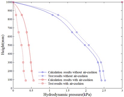
Table 1Comparison of dynamic characteristics
Parameter | Test results without air-cushion | Calculation results without air-cushion | Test results with air-cushion | Calculation results with air-cushion |
(Hz) | 56.6 | 59.2 | 67.2 | 65.1 |
(Hz) | 71.8 | 73.5 | 85.3 | 82.0 |
(Hz) | 98.7 | 105.1 | 112.6 | 118.6 |
(g) | 2.43 | 2.23 | 1.75 | 1.84 |
Note: , ,, are the 1st, 2nd, and 3rd order frequency, respectively. is the peak value of acceleration on the dam crest | ||||
4. Project case
4.1. Calculation model
Take a concrete double-curvature arch dam with height of 305 m and designed peak acceleration of 0.197 g as an example. The numerical simulation was conducted with the above-mentioned dynamic analysis model to analyze the air-cushion’s effect on the reduction in dynamic response of the dam and crack area under earthquake loading. A wildlife seismic wave (shown in Table 2) is adopted and same-ration scaled with peak accelerations at 1.0, 1.5, 2.0, and 2.4 in a longitudinal flow direction ( axis). The peak accelerations of latitudinal direction ( axis) and vertical direction ( axis) are 2/3 of that of the longitudinal direction. The wave shape is shown in Fig. 6 for a peak acceleration in longitudinal direction of 1.0. The calculation period is 20 s and the time step is 0.02 s.
Table 2Basic information of wildlife seismic wave
Location | Superstition hills (USA) |
Seismographic station | United States geological survey |
PGA in FN direction (g) | 0.102 |
PGA in FV direction (g) | 0.186 |
PGA in UP direction (g) | 0.148 |
Fig. 6Time history of wildlife seismic wave
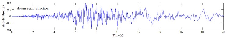
a)
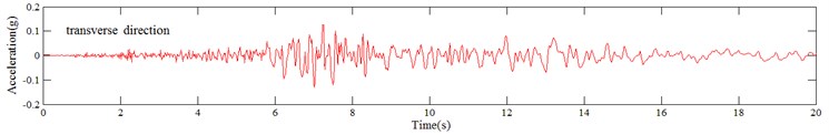
b)
c)
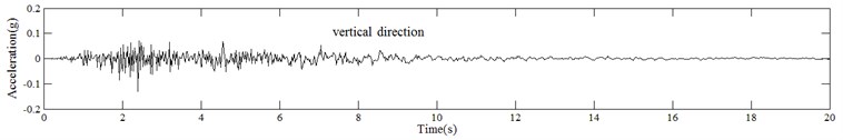
The dimensions of the dam base are taken as 1200×600×1200 m. The water level is normal pool level and the geological and topographic conditions are simplified. The dynamic elasticity modulus of the dam base is 26 GPa. The density is 2500 kg/m3, and Poisson’s ratio is 0.25. The dynamic elasticity modulus of the dam is 39 GPa, the density is 2400 kg/m3, and Poisson’s ratio is 0.163. The dynamic tensile strength and compressive strength are 2.5 MPa and 40 MPa respectively; is 0.2, is 0.8, and is 0.2; the density of water is 1000 kg/m3; the acoustic speed in water is 1430 m/s; the thickness of the air-cushion is 1 m, and the density and bulk modulus of the air-cushion element is defined according to the centroid pressure (including atmospheric pressure) of the element. The contact element is taken to the horizontal joints of the dam sections. To simulate the keyway’s constraining effect on the relative slippage of the dam, the relative slippage between dams is neglected by coupling the tangential freedom of the horizontal joint interface. Radiation damping of dam base is considered by adopting a viscoelastic artificial interface and realized by adopting a Combin14 spring damping element. The acceleration shown in Fig. 6 is integrated with time to obtain the speed-time history and displacement-time history of the free field and further calculate the node force vector of the viscoelastic artificial interface. Rayleigh damping is adopted and the scaling coefficient is determined according to the natural frequency of the previous five stages. The integral finite element model is shown as Fig. 7, and is divided into 91 012 elements and 92 797 nodes. The calculation cases are shown in Table 3.
Fig. 7Finite element model
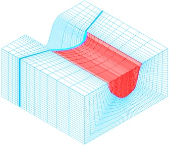
Table 3Computational cases
Case | 1 | 2 | 3 | 4 | 5 | 6 | 7 | 8 |
Peak value of acceleration | 1.0 | 1.0 | 1.5 | 1.5 | 2.0 | 2.0 | 2.4 | 2.4 |
Air-cushion | × | √ | × | √ | × | √ | × | √ |
4.2. Analysis results
4.2.1. Hydrodynamic pressure
Fig. 8 shows the envelope diagram of the hydrodynamic pressure on the upstream face of the dam under different working conditions. The extreme hydrodynamic pressure is shown in Table 4.
Fig. 8Envelop diagram of hydrodynamic pressure on dam upstream face (unit: kPa)
a) Case 1
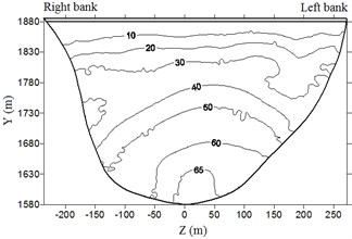
b) Case 2
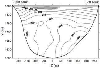
c) Case 3
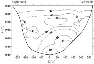
d) Case 4
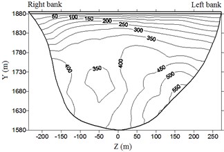
e) Case 5
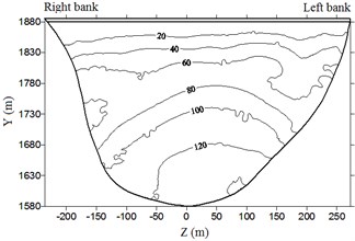
f) Case 6
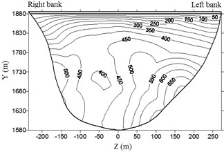
g) Case 7
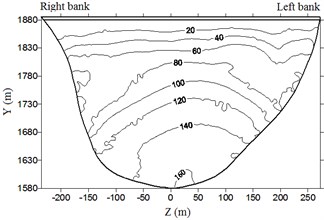
h) Case 8
Table 4Response of hydrodynamic pressure
Case | 1 | 2 | 3 | 4 | 5 | 6 | 7 | 8 |
Maximum value (kPa) | 283.4 | 81.5 | 420.2 | 116.2 | 572.1 | 155.8 | 716.6 | 187.1 |
Reduction (%) | – | 71.2 | – | 72.3 | – | 72.8 | – | 73.9 |
It is clear from the Fig. 8 and Table 4 that hydrodynamic pressure basically increases with water depth and peak earthquake acceleration. Extreme hydrodynamic pressure is approximately positively related to peak acceleration; the air-cushion reduces the water pressure significantly; when acceleration is 1.0, 1.5, 2.0, and 2.4, the reduction in extreme hydrodynamic pressure is 71.2 %, 72.3 %, 72.8 %, and 73.9 %, respectively. With an increase in peak acceleration, the air-cushion’s reduction effect on hydrodynamic pressure is slightly increased.
4.2.2. Acceleration response
Fig. 9 shows the acceleration time history response at the top of the dam for cases 5 and 6. The peak acceleration response at the top of the dam under different working conditions is shown in Table 5.
Fig. 9Comparison of acceleration on dam crest
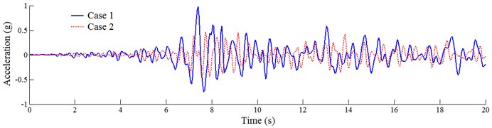
Table 5Response of acceleration on dam crest
Case | 1 | 2 | 3 | 4 | 5 | 6 | 7 | 8 |
Maximum value (g) | 0.48 | 0.23 | 0.74 | 0.35 | 0.98 | 0.46 | 1.21 | 0.55 |
Reduction (%) | – | 52.1 | – | 52.7 | – | 53.1 | – | 54.5 |
It is clear from Fig. 9 and Table 3 that the extreme acceleration at the top of the dam is considerably higher than the input peak acceleration of the seismic wave, and the dynamic scale-up effect is obvious; after placing the air-cushion, the acceleration of the dam is reduced significantly; when the acceleration is 1.0, 1.5, 2.0, and 2.4, the reduction in extreme acceleration at the top of the dam is 52.1 %, 52.7 %, 53.1 %, and 54.5 %, respectively, and the dynamic scale-up effect is weakened and the anti-quake performance of the dam is further improved. With the increase in peak acceleration, the air-cushion’s reduction effect on the acceleration response is also increased slightly.
4.2.3. Crack area on dam
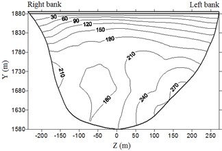
Fig. 10 shows the cracks on the dam under different working conditions. Without the air-cushion, the cracks are predominantly concentrated on the dam base of the upstream face and upper part of the downstream face. With the increase in peak acceleration, the crack area on the dam increases; after placing the air-cushion, the crack area on the dam is effectively controlled. Under the working conditions stipulated in this paper, after placing the air-cushion, cracks only occur on the dam base and section near the right dam shoulder. The seismic isolation effect is obvious.
Fig. 10Cracking state of dam body
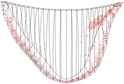
a) Case 1
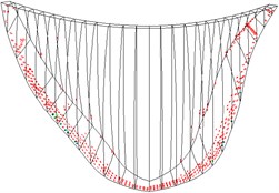
b) Case 2
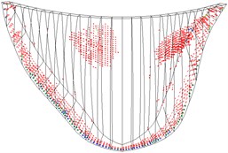
c) Case 3
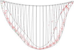
d) Case 4
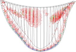
e) Case 5
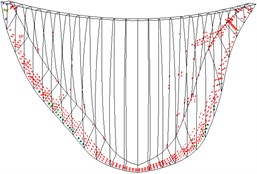
f) Case 6
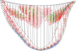
g) Case 7
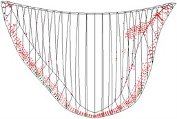
h) Case 8
5. Conclusions
Owing to the particularity of the structure and ambient environment of the arch dam, it is difficult to directly apply the conventional energy dissipation and seismic isolation method to a hydraulic structure. Air-cushion seismic isolation provides a novel idea for dynamic control of large-scale hydraulic concrete structures. In this paper, the cracking behavior of dam concrete is considered for the first time in numerical simulation of air-cushion seismic isolation. By studying the seismic isolation effect of a 305 m high arch dam, the following conclusions are obtained:
1) The air-cushion can significantly reduce the hydrodynamic pressure on the upstream face of the arch dam and further reduce the attached load under earthquake conditions. When the air-cushion is 1 m thick, the hydrodynamic pressure on the upstream dam face is reduced by more than 70 %; with an increase in peak acceleration, the air-cushion’s reduction effect on hydrodynamic pressure is slightly increased.
2) The air-cushion can significantly reduce the acceleration of the dam and weaken the dynamic scale-up effect. This further improves the anti-quake performance of the dam. Extreme acceleration at the top of the dam is reduced by more than 50 %; with an increase in peak acceleration, the air-cushion’s reduction effect on acceleration response is also increased.
3) Cracks are mainly concentrated on the dam base of the upstream face and upper part of the downstream face. With an increase in peak acceleration, the crack area on the dam dramatically increases. The air-cushion effectively reduces the crack area on the dam, and the seismic isolation effect is obvious.
References
-
Long Y. C., Zhang C. H., Jin F. Numerical simulation of reinforcement strengthening for high-arch dams to resist strong earthquakes. Earthquake Engineering and Structural Dynamics, Vol. 37, Issue 15, 2008, p. 1739-1761.
-
Long Y. C., Zhang C. H., Xu Y. J. Nonlinear seismic analyses of a high gravity dam with and without the presence of reinforcement. Engineering Structures, Vol. 31, Issue 10, 2009, p. 2486-2494.
-
Liu H. W., Zhang S. J., Chen J., Sun M., Sun L., Li Y. Simulation analysis theory and experimental verification of air-cushion isolation control of high concrete dams. Science in China Series E: Technological Sciences, Vol. 54, Issue 11, 2011, p. 2854-2868.
-
Li N. S., Lou M. L., Zhou J., Xie L. H. Seismic response of high-arch dams with contraction joints connected by springs and dampers. China Civil Engineering Journal, Vol. 41, Issue 5, 2008, p. 94-99.
-
Sun W. Q. Seismic response control of high arch dams including contraction joint using nonlinear super-elastic SMA damper. Construction and Building Materials, Vol. 25, Issue 9, 2011, p. 3762-3767.
-
Kalpakidis I. V., Constantinou M. C., Whittaker A. S. Effects of large cumulative travel on the behavior of lead-rubber seismic isolation bearings. Journal of structural engineering, Vol. 136, Issue 5, 2009, p. 491-501.
-
Kalpakidis I. V., Constantinou M. C., Whittaker A. S. Modeling strength degradation in lead-rubber bearings under earthquake shaking. Earthquake Engineering and Structural Dynamics, Vol. 39, Issue 13, 2010, p. 1533-1549.
-
Westergaard H. M. Water pressures on dams during earthquakes. Transactions of the American Society of Civil Engineers, Vol. 98, Issue 2, 1933, p. 418-433.
-
Aznáreza J. J., Maesoa O., Domínguez J. BE analysis of bottom sediments in dynamic fluid-structure interaction problems. Engineering Analysis with Boundary Elements, Vol. 30, Issue 2, 2006, p. 124-136.
-
Bayraktar A., Hançer E., Akköse M. Influence of base-rock characteristics on the stochastic dynamic response of dam–reservoir–foundation systems. Engineering Structures, Vol. 27, Issue 10, 2005, p. 1498-1508.
-
Akkōse M., Adanur S., Bayraktar A., Dumanoglu, A. A. Elasto-plastic earthquake response of arch dams including fluid-structure interaction by the Lagrangian approach. Applied Mathematical Modelling, Vol. 32, Issue 11, 2008, p. 2396-2412.
-
Latorre R. Ship hull drag reduction using bottom air injection. Ocean Engineering, Vol. 24, Issue 2, 1997, p. 161-175.
-
Ceccio S. L. Friction drag reduction of external flows with bubble and gas injection. Annual Review of Fluid Mechanics, Vol. 42, 2010, p. 183-203.
-
Slyozkin A., Atlar M., Sampson R., Seo K.-C. An experimental investigation into the hydrodynamic drag reduction of a flat plate using air-fed cavities. Ocean Engineering, Vol. 76, 2014, p. 105-120.
-
Mraz Stephen J. It’s all in the spring. Machine Design, Vol. 70, Issue 8, 1998, p. 80-86.
-
Zhang S. J., Chen J., Zhang Y. Z., Liu H. W. Research of air-cushion isolation effects on high arch dam reservoir. Acta Mechanica Sinica, Vol. 27, Issue 5, 2011, p. 675-686.
-
Zhong H., Lin G., Li X. Y., Li J. B. Seismic failure modeling of concrete dams considering heterogeneity of concrete. Soil Dynamics and Earthquake Engineering, Vol. 31, Issue 12, 2011, p. 1678-1689.
-
Pan J. W., Zhang C. H., Wang J. Y., Xu Y. J. Seismic damage-cracking analysis of arch dams using different earthquake input mechanisms. Science in China Series E: Technological Sciences, Vol. 52, Issue 2, 2009, p. 518-529.
-
Pan J. W., Zhang C. H., Xu Y. J., Jin F. A comparative study of the different procedures for seismic cracking analysis of concrete dams. Soil Dynamics and Earthquake Engineering, Vol. 31, Issue 11, 2011, p. 1594-1606.
About this article

Thanks to the open fund Program of MOE Key Laboratory of Deep Underground Science and Engineering, China (Grand No. 2013KF07) for the financial support.
